Page 5 of 6

Drywall, Level 0 – June 2021

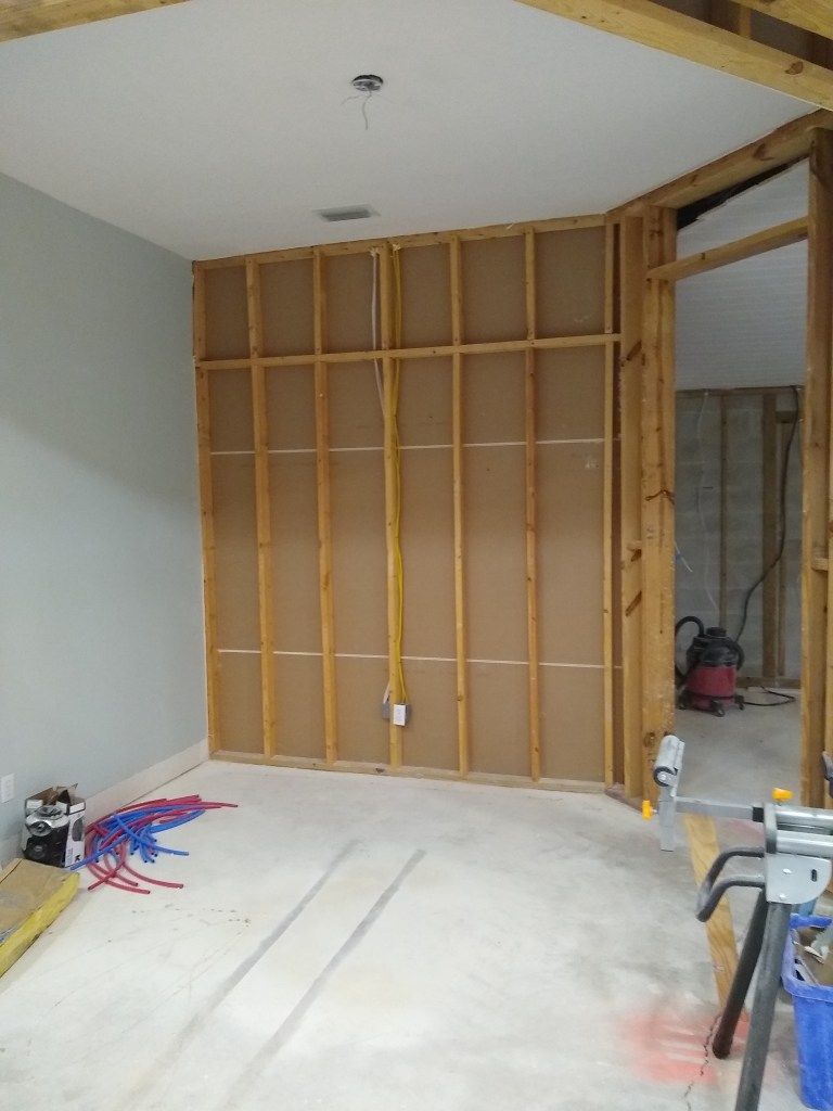
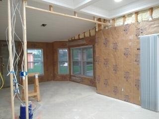
I took an unplanned hiatus through most of May, initially due to a cold. Once recovered from that, I was further delayed by my own hesitation about pulling the trigger on the drywall. I wanted to make sure that was the next step before I made the purchase. After convincing myself that it was, I took the measurements to establish how many sheets I would need, excluding the master bathroom (not sure what I’ll do there yet), My objective was to use as large a sheet as I could where possible to reduce the seems that would subsequently require taping. My measurements revealed that I would need 35 sheets of 12’x4′ and 60 sheets of 8’x4′.

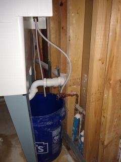
I first visited Lowe’s intent on making a purchase and arranging delivery. Unfortunately, Lowe’s would only deliver the drywall to my garage. I wanted it placed inside the house. I would be hanging it by myself, so moving it from the garage into the work space would be a major chore by myself. So I went to Home Depot next and, fortunately, for an extra charge they would carry it into the house. I didn’t make the purchase that day. Instead I went home and looked online for other options before I committed to it. I didn’t find anything, so I called Home Depot and made the arrangements over the phone. We set a date and a time window .

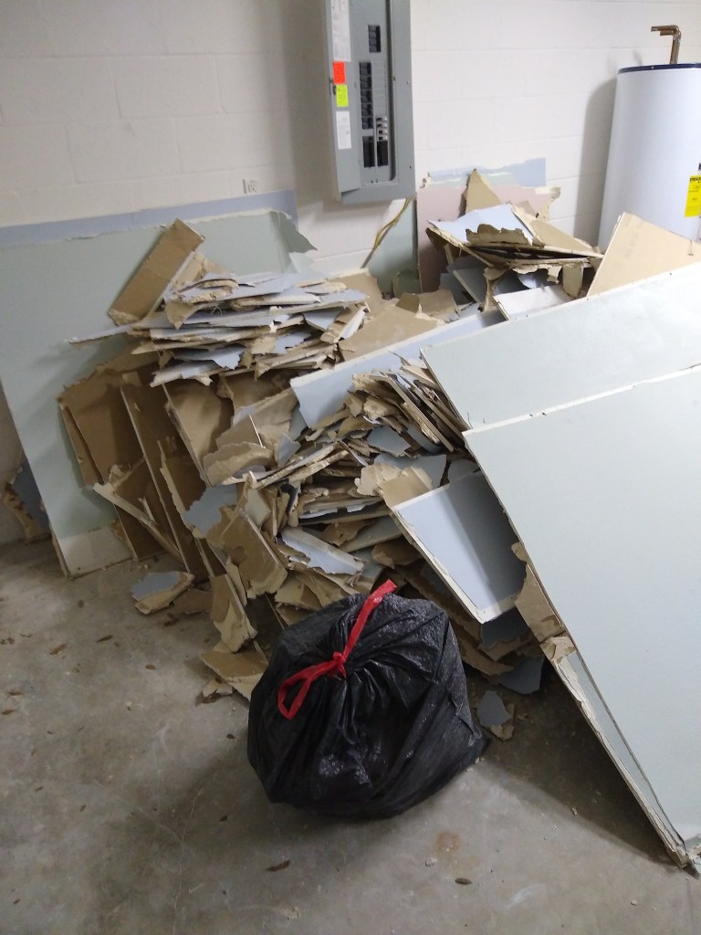
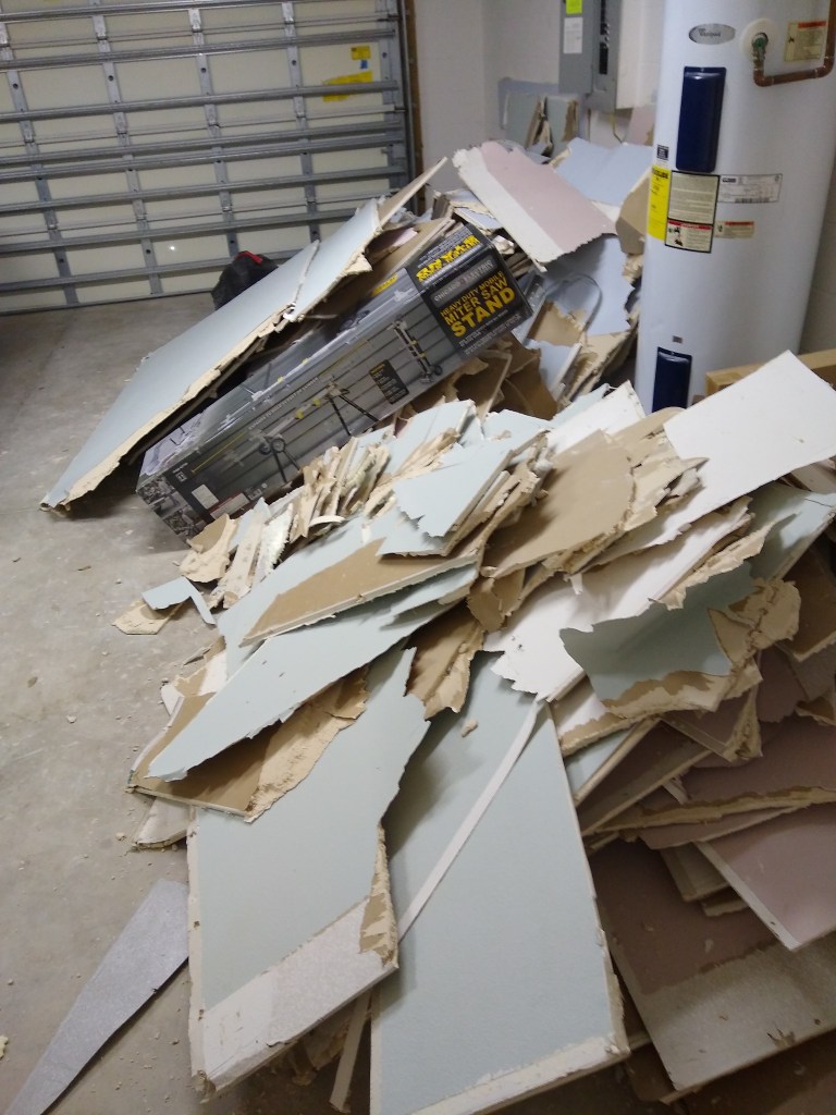
I drove up to meet the delivery crew on Wednesday, May 19th at the designated time. When the driver arrived he was by himself, which surprised me because moving all the drywall into the house would be a big job for one person. I mentioned this when he approached me only to learn that he was not planning to carry it into the house; only put it in the garage. So, he got on the phone with the store for about half an hour with little result. In the end he left without unloading the drywall. So I drove to the store to discuss it with them. They made arrangements for another attempt on the Monday, May 24th, this time with additional labor. I drove up again on the Friday and waited. I stopped in at the store to make sure all was in order and was told it was. Nearing the end of the delivery window I got a call informing me that they’d have to do something else because the usual delivery service did not carry into the house. So we set it up for the following Friday. The third attempt was successful. My drywall was placed where I asked.

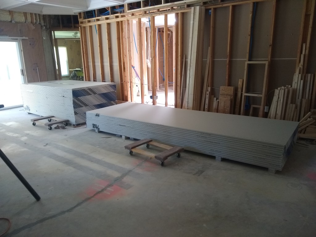
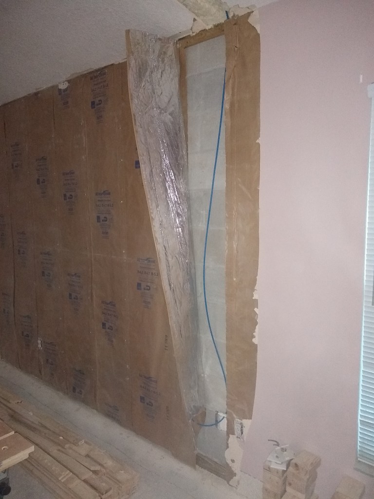
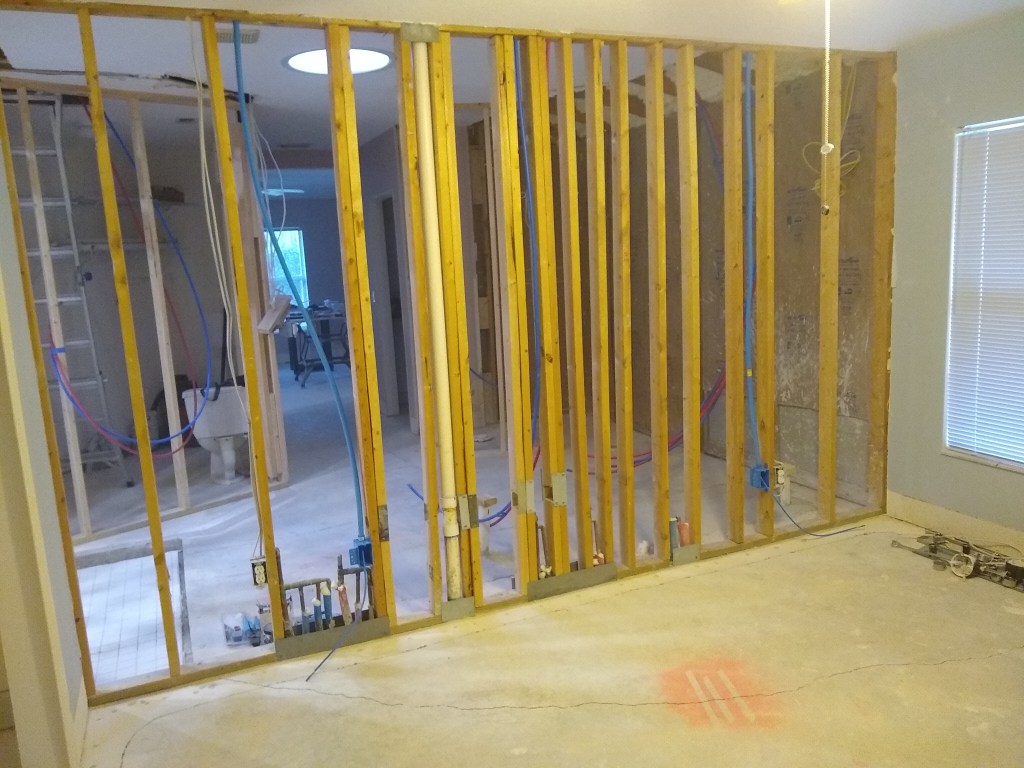
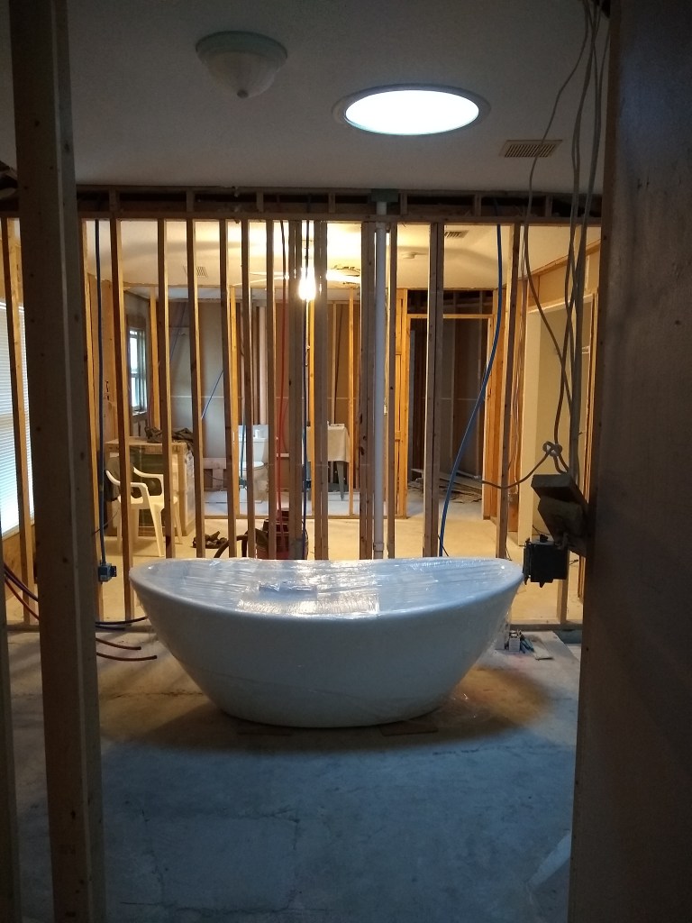
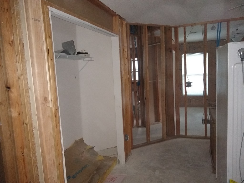
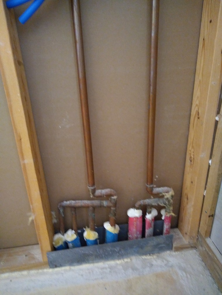
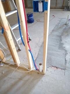
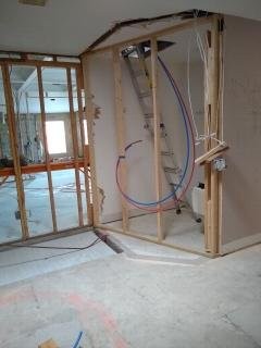
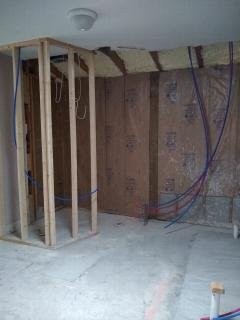
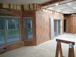
Note that the above pictures were taken after I had already finished hanging the drywall in the guest bedroom, so if you looked really closely, you’ll see that there are less than 35 sheets of the 12′.

The next day I hung my first ever sheet of drywall! I had several reservations about doing this myself, especially with the 12′ sheets. My biggest concern was how I was going to mount a 12′ sheet on the upper section of the wall up to the ceiling. I did some research on YouTube and learned that I could do it using the lift I had. Until viewing that video, I’d only used the lift for raising things up to the ceiling and was unaware that it had features to assist with hanging drywall on high walls. That was my first and biggest problem solved. I would not have to rely on another person. A big relief.

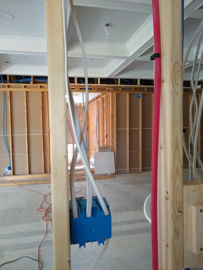
Another concern I had was how I would maneuver the sheets from one room to another. I was pretty sure I could use a couple of dollies I had, and that turned out to be the case. At first I used both dollies. It worked, but was little tricky steering. I then discovered that using one was sufficient and much more maneuverable. So another problem solved. Below I show a big 12′ sheet on the single dolly.

Moving Drywall Sheets

Now that I’ve shown how I move the sheets by myself, let me show the process of hanging a 12′ sheet. Using the dolly, I move the sheet into the room I am working on and get it close to the lift. I then have to physically pick up the sheet and place it onto the lift. That is not easy, but after trying several techniques I figured out how to do it without too much effort.

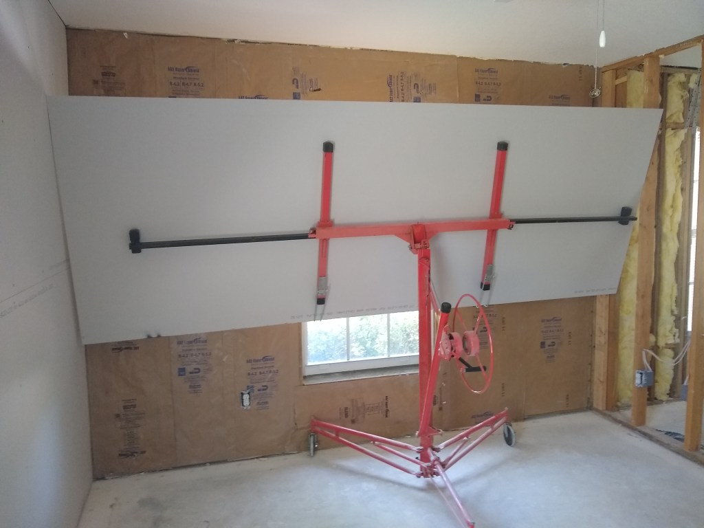
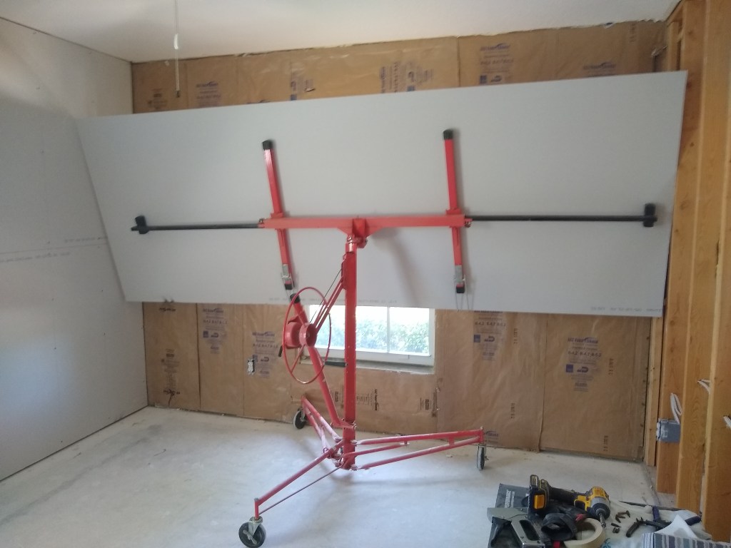
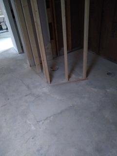
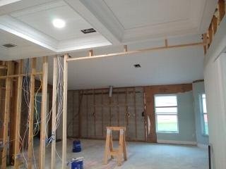
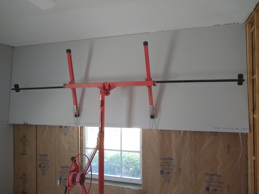
The pics above are of the sheet on the lift positioned to go on the north wall of what will be the office. I had already finished hanging the guest bedroom and the west wall in the office before I started writing this post. It was only when I started describing the process that I realized that pictures were required. So what you’re seeing is not my first attempt. The pics show the lift moved close to the wall. This is the first step. Next I must tip the top of the sheet so that it rests against the wall. In the image below, you can see that the bottom edge of the sheet is still supported by the lift, but the top edge is not. It is now leaning against the wall. For this to work without the lift rolling away, it has a set of brakes with rubber ends to prevent the lift from moving.

On Lift, Against the Wall

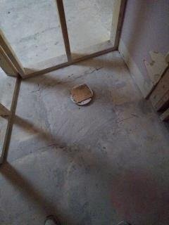
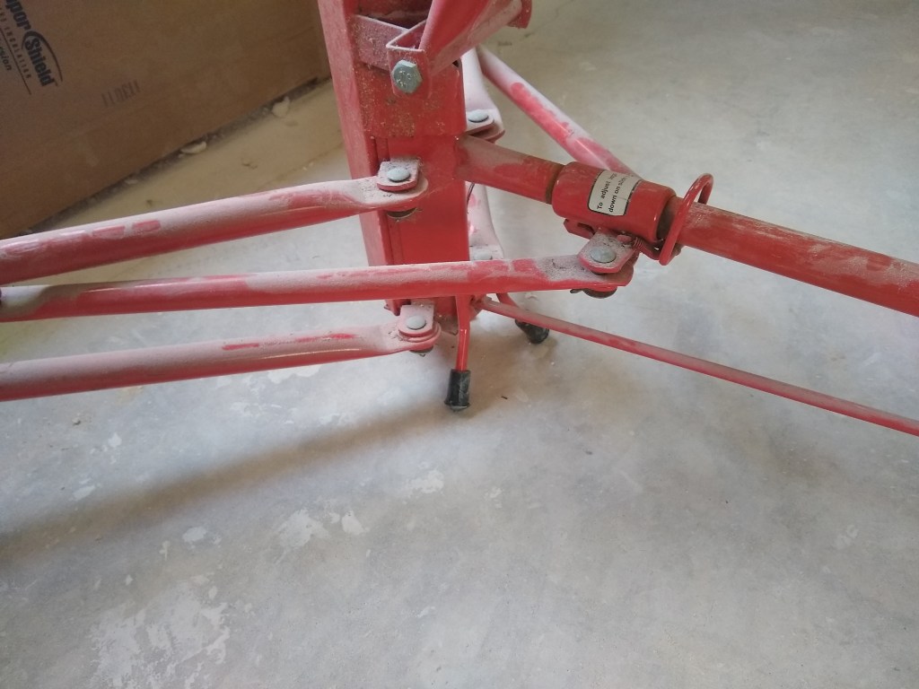
Here is a closeup of the brakes deployed.

Lift Brakes

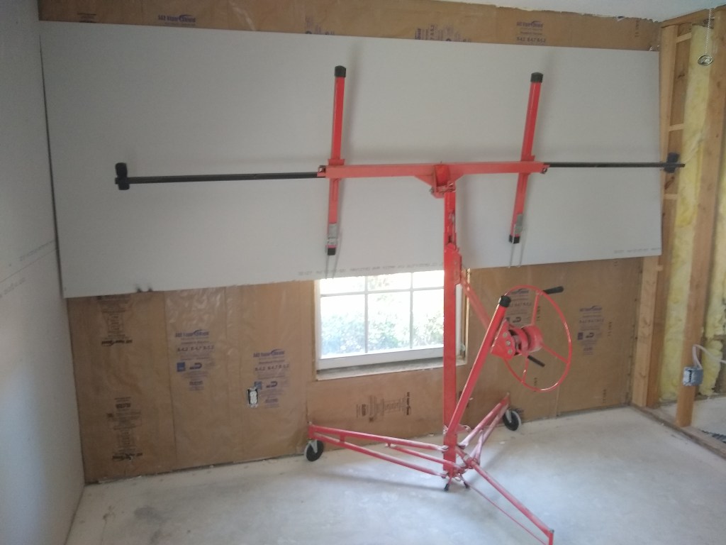
Now I just raise the sheet into position. It simply rides up against the wall as I turn the handle.

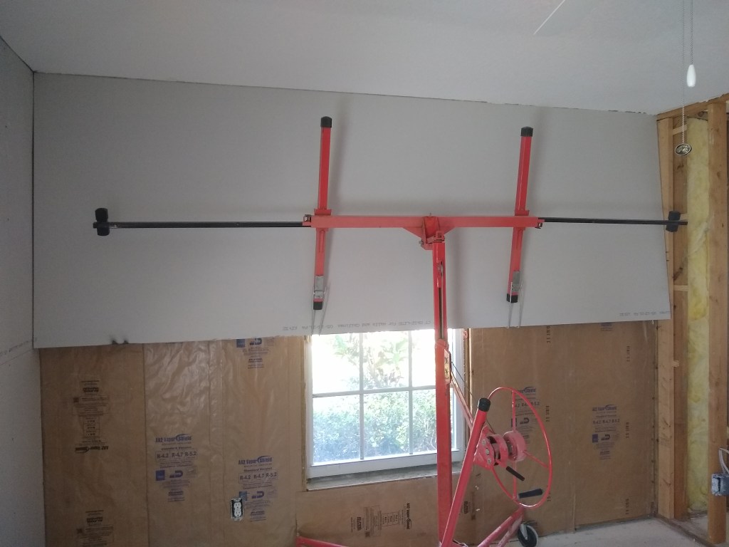
Actually, with a tight fit like this one, it takes a bit of maneuvering. I turn the crank, adjust the sheet, turn the crank, etc. But it is pretty straight forward. Once in position I pull out the ladder and drill a few screws into place at the top. Three screws are enough. Then I can roll the lift away and it will hang by itself.

Sheet tacked and Lift removed.

After that it is just a matter of adding enough screws to firmly fix it in place. Before I place the bottom sheet which, of course, does not require the lift, I cut out the window opening. But I will discuss those details later. Now that I have explained the process of hanging sheets, I will describe what I experienced as I began the process.

Being new to this, I decided it would be a good idea to gain experience (i.e., make beginner mistakes) in a room that would be the least used. So I started in the guest bedroom. I figured out how to move and lift the sheets by myself, as described above, but there were still several other firsts I had to face.

The first sheet I hung was a full 12’x4′ sheet, requiring no cuts. Here it is below.

The next sheet, however, would require cutting to fill the relatively small area adjacent to my first sheet. Cutting a sheet seemed pretty simple, so I just followed the directions I found online. Sure enough, it was simply a matter of cutting a line through the paper with a utility knife, then snapping it. The sheet broke easily on the scored line. I then used the same knife to reach under and cut the paper on the other side. Voila, another mystery solved. It also required one more step; using a rasp to smooth the freshly cut edge, but that was very simple using the following tool.

Drywall Rasp Lifter

This tool has two uses. It can be used to raise the bottom of a sheet of drywall using your foot and a lever action to meet the sheet already in place above it. The idea is to create a tight butt joint. The other use comes from the part in the middle of the tool that is a rasp you can run along the edge of a freshly cut sheet to smooth it out. It works really well.

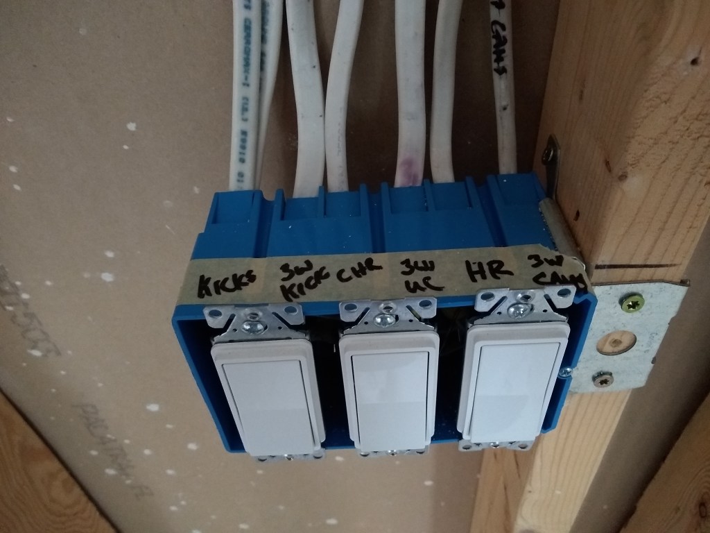
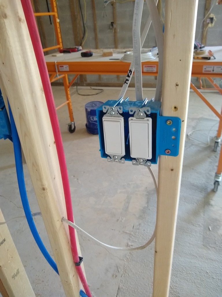
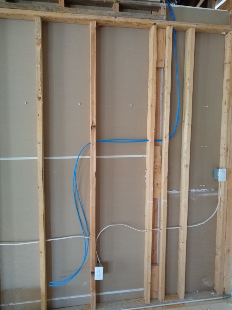
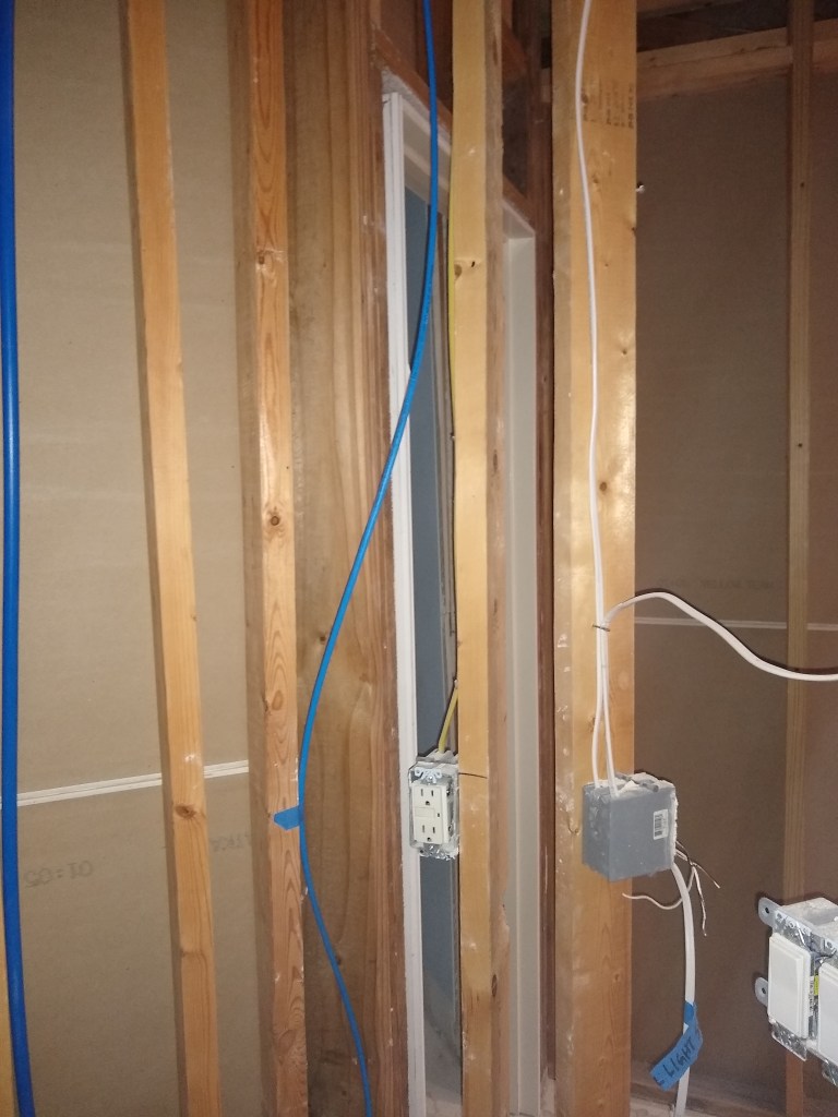
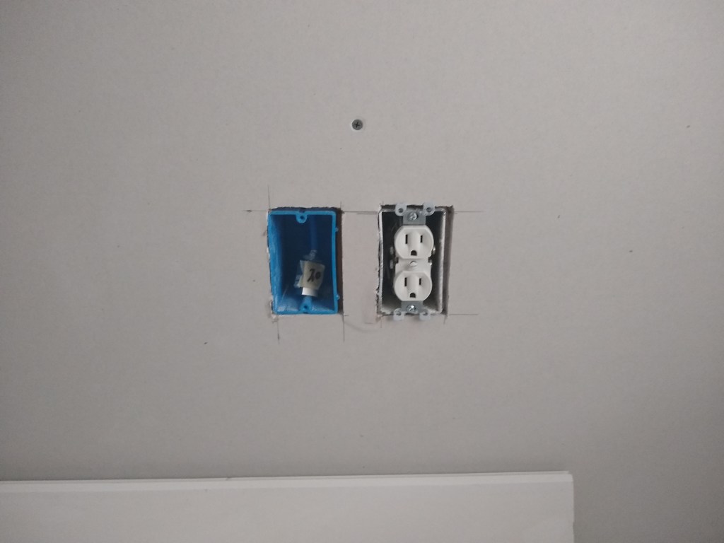
So I fastened that piece to the end of my first sheet to finish the top of my first wall. The bottom part was a bit more involved, since it required some cuts for outlets, as shown below.

First Wall Hung

To cut the openings for the outlets, I started using the manual approach whereby you simply measure the distances and then cut with a drywall saw.

Drywall Saw

This worked fairly well, but it was very time consuming. It also had the disadvantage of not always lining up how you expect. You measure as best you can, but when you actually fit the sheet, there will inevitably be some variance. Here is what it looks like close up.

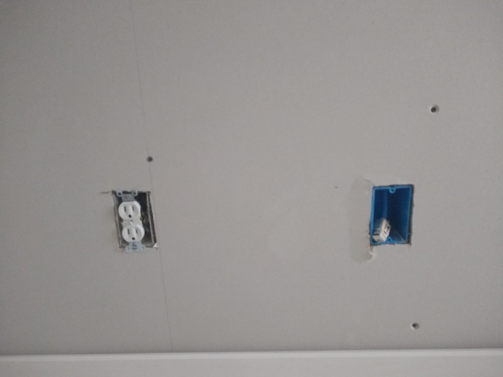
These are not bad and will be easily covered by the face places, so no patching will be required. However, the measuring and cutting before putting the sheet up really interrupts ones momentum, so I decided to try my hand at using a cutting tool with a RotoZip bit. Here is what I bought.

Notice that the RotoZip Bit has a smooth tip. This is the part the will guide the bit along a surface without cutting it, as I describe in a moment.

My research revealed that a cutting tool and RotoZip bit seemed to be the preferred method used by professionals. The concern for me was that it was going to take some practice to learn how to use it without making a mess. The way it works, is that you first remove the outlet and push the wired to the back of the box. You make a note of where the center of the box is then place the sheet over the outlet and fasten it loosely using screws that are not really close to the outlet itself. You measure to where you noted the center of the box to be and plunge in with the cutting bit. You then move the bit (i.e., cut) over to the edge of the box. You’ll feel the bit stop when it touches the inside edge of the box. Then you pull the bit out a little and move the bit over to the outside edge of the box and trace around it, cutting away the drywall. This is the tricky part for the inexperienced. You have to get a feel for it, which takes a bit of time. Here are my first three attempts.

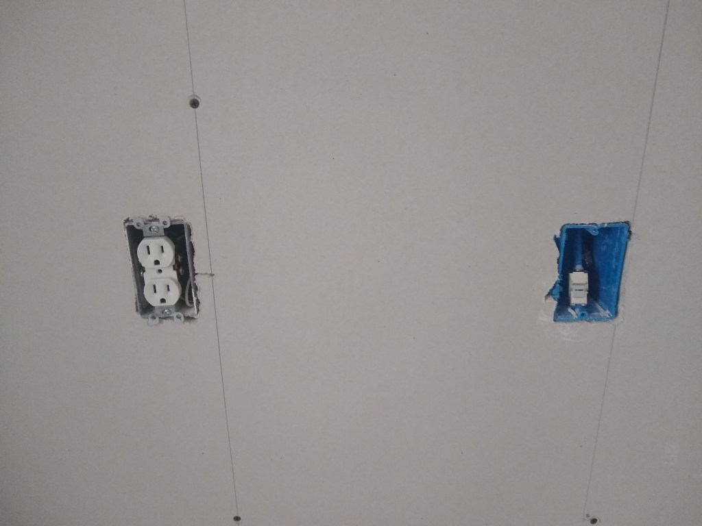
As you can see, these are pretty ugly, especially the third one, and will require patching. For a professional, patching mistakes like this is a real nuisance, costing time/money. However, for me, I am not time constrained, so I will “embrace the suck” and view this as part of the process. I did get better and expect I will continue to. Here are my fourth and fifth attempts. They are not perfect, but are acceptable and will require no patching.

Fourth and Fifth RotoZip Attempts

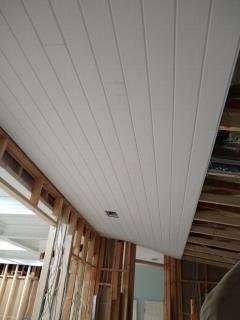
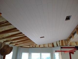
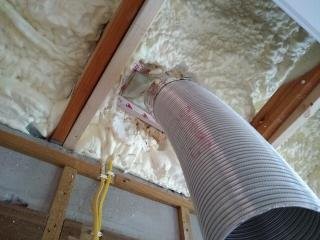
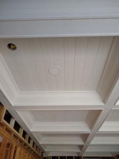
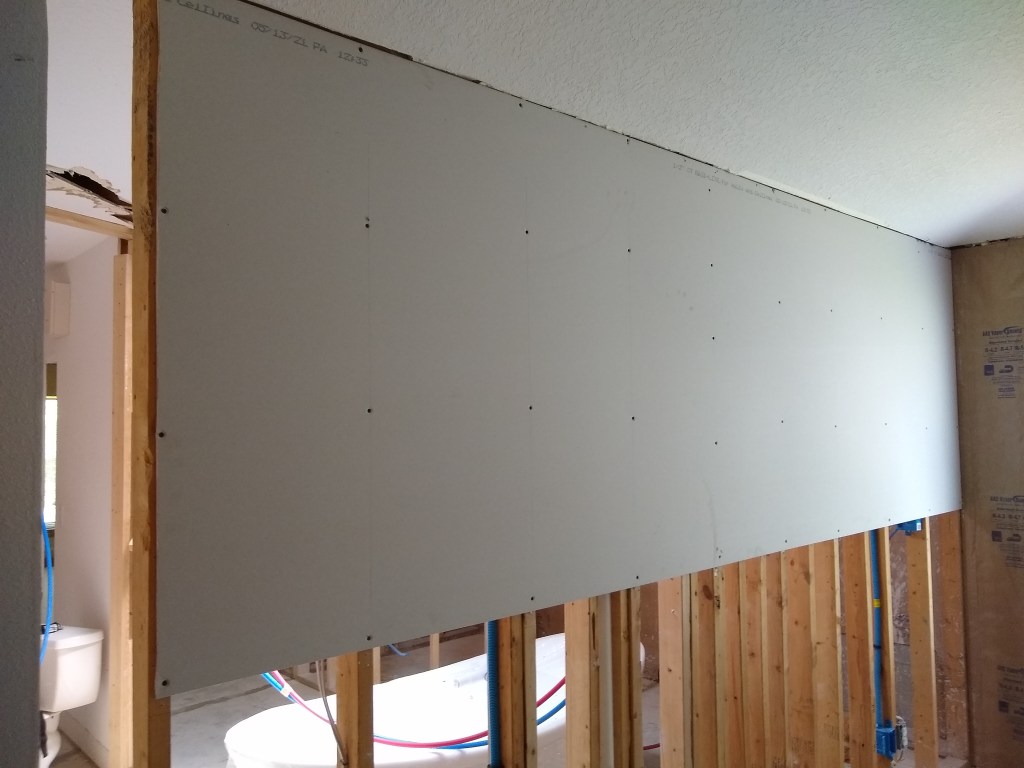
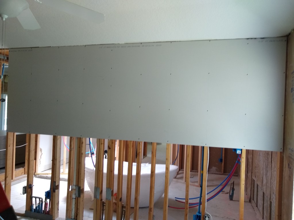
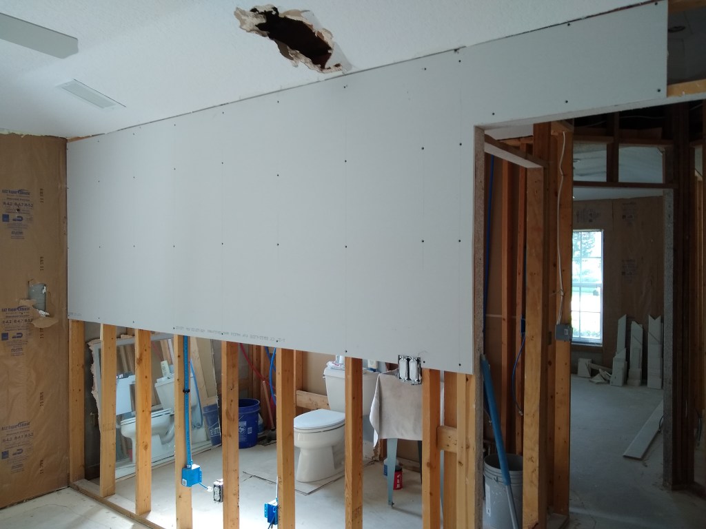
I also use the cutting tool for other openings, like doors and windows. Here is the second wall I started in the guest bedroom. The 12′ sheet covered the doorway, so I used the cutting tool to open it up after the sheet was in place. It works nicely for this and is a much simpler process as one simply follows the door frame (no need to pull out and plunge in). As a side note, the hole in the ceiling was done a long time ago as we explored the framing. It will be patched in due course.

Cutting the Opening for the Door

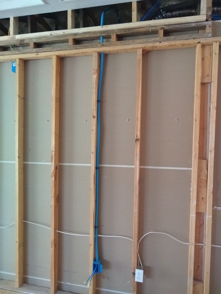
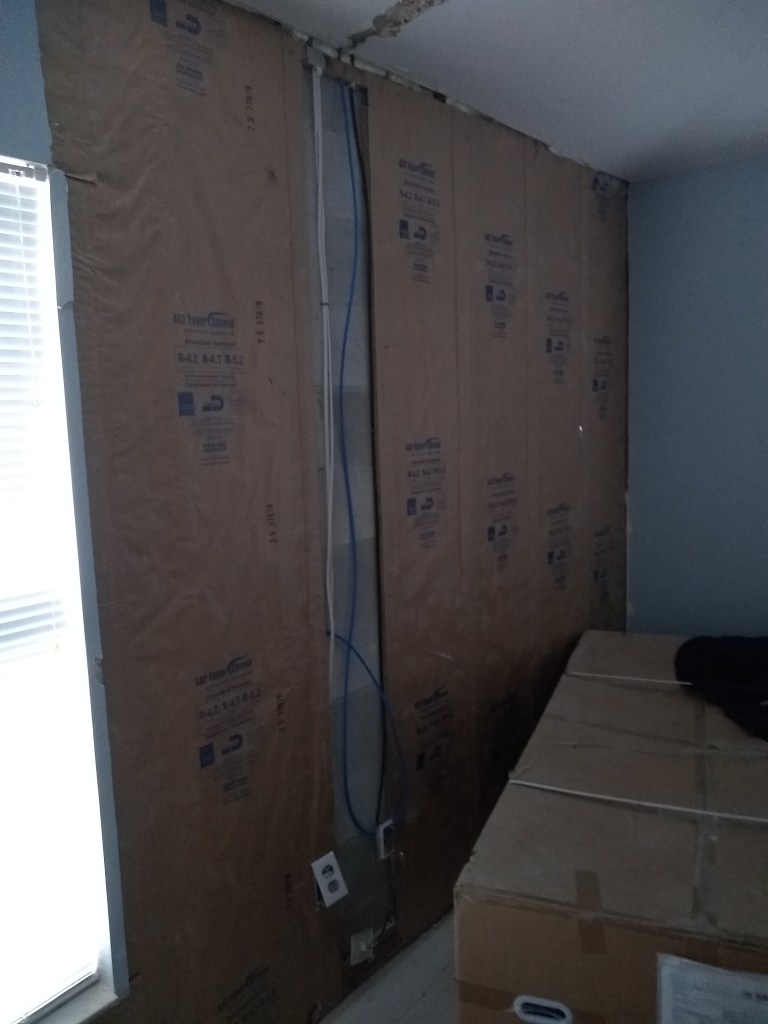
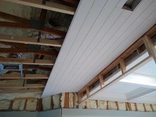
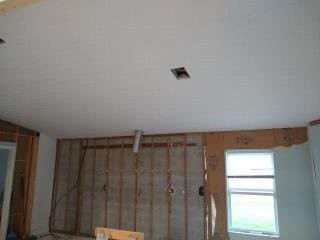
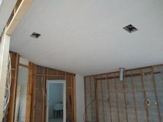
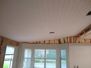
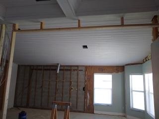
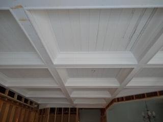
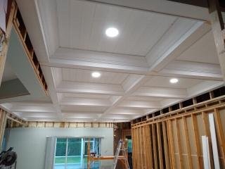
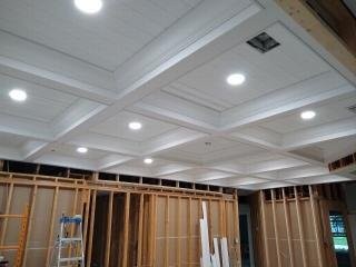
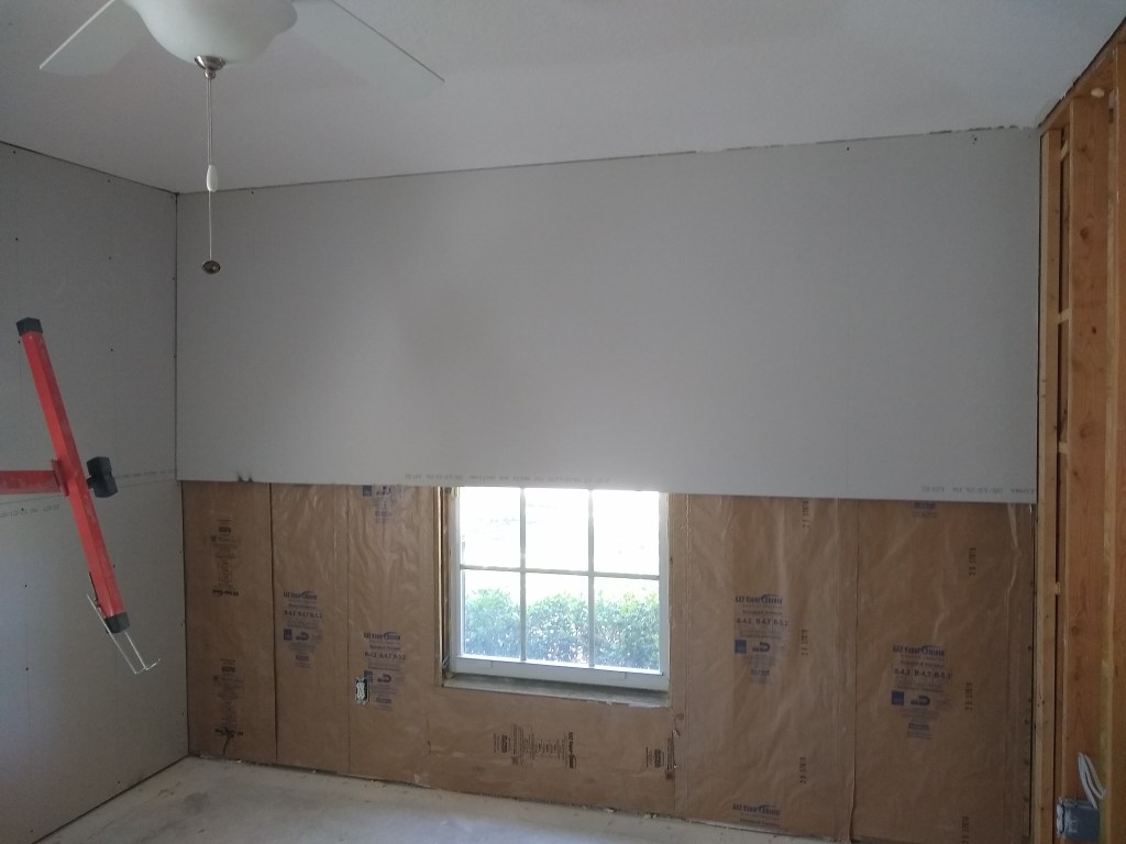
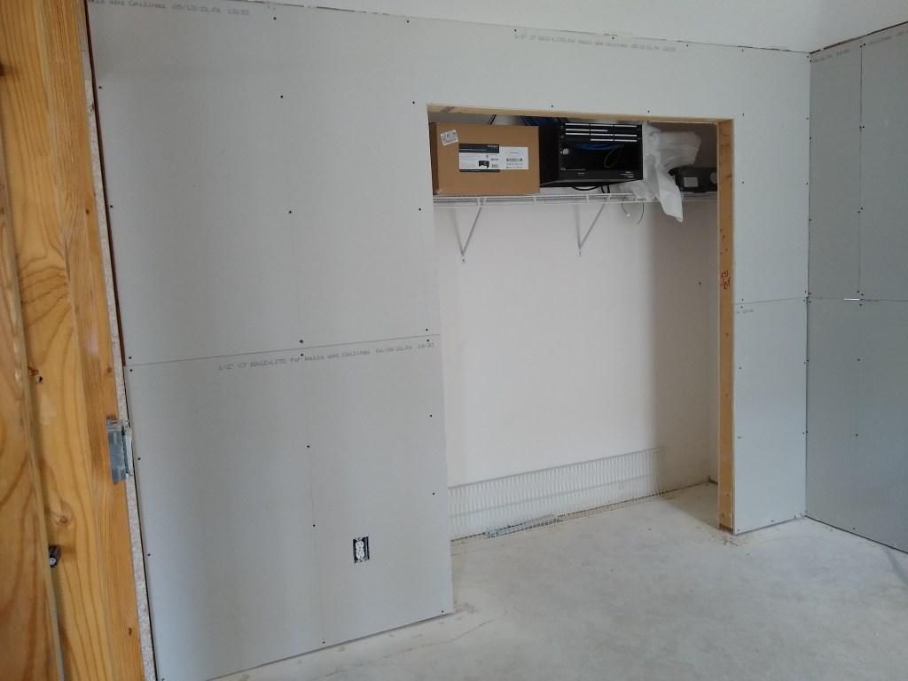
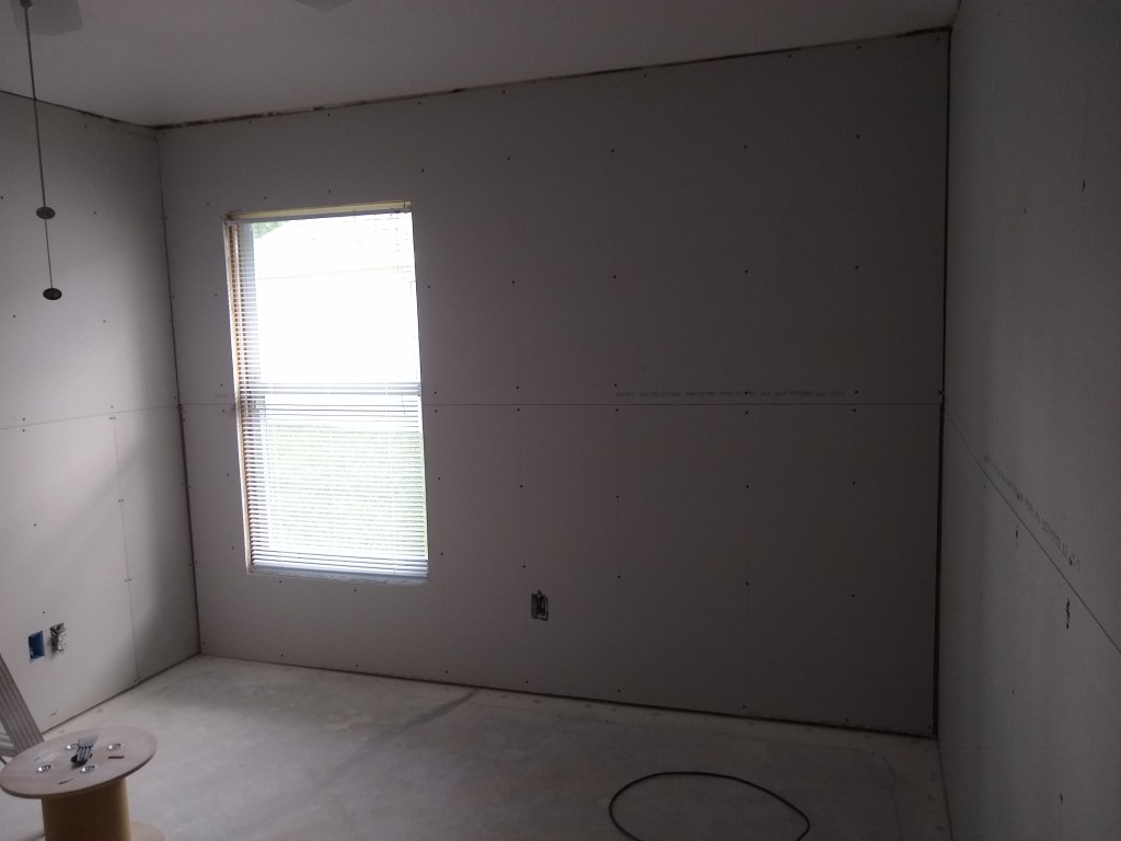
Here are a few shots of the guest room after I finished hanging the drywall.

During the process of hanging the drywall in the guest bedroom, I found that setting the screws was a bit erratic with the impact driver, even using drywall screw setter bits to limit the likelihood that I would drive the screws too deeply into the drywall. You’re supposed to sink them below the surface without breaking the paper. So I decided to purchase a drywall screw gun; a tool specifically designed for this.

Drywall Screw Gun

With this tool, when you pull the trigger, the motor spins, but the bit does not turn until you press the screw into the drywall. It is the pressure that causes the clutch to engage, and then it drives it in quickly. You can adjust the depth to sink the screw head to your desire depth. I found this was a very worthwhile purchase and made the process much more consistent. I’m very happy with it.

In addition to screws, I am also using construction adhesive to glue the sheets to the studs, where possible. Although many were split on the need for it, it appeared that most felt it was worth while and that it would reduce the likelihood of screw pops in future. The idea is that as the framing naturally moves (slightly) over time, the extra adhesion will prevent the drywall from pushing and pulling against the screws. The extra cost for the adhesive is not much and it takes very little time to apply, so I figured I’d do it. Unfortunately, it can only be done on interior walls, since the furring strips you screw to on the exterior walls are covered with an insulating material, so I’m not getting 100% coverage.

Some other lessons I learned while hanging the drywall in the guest bedroom was that it is a good idea to look for opportunities to do some prep work. Many walls are not straight and will require shimming. Also, in some places, especially in the corners, there is not always a lot of wood available to screw the sheet to, so it can be beneficial to add nailers.

As of the time of this posting, I have hung two bedrooms (guest bedroom and office) and am half way through the third bedroom (workshop). I have ordered 100 feet of mass loaded vinyl to use as sound insulation between the workshop and office, which will arrive this weekend. I will put it up and see how it works before purchasing more for the other interior walls to which I intend to add sound insulation. Where it makes sense, I want to reduce the sound that can travel between rooms (i.e., bathrooms and bedrooms). But I’ll talk about that in another post. Once the drywall in the workshop is hung, I think I will return to the guest bedroom and try my hand at mudding and taping so I can get some experience with that before continuing with the hanging. It is likely that the lessons learned from that experience will impact how I hang the remaining drywall. Since there is so much more drywall to hang, now’s the time to discover them. So stay tuned.

New Window Preparation and Some Floor Repairs – April 2021

As mentioned in the last post, I will be replacing my windows and doors with ones that are impact resistant. Additionally, I will be replacing the double window in the bay area of the kitchen with french doors that open out to the lanai. To start the process I selected three vendors and had them come by to measure and provide estimates. During that process I learned that vinyl windows were a bit less expensive, but that the vinyl frame is wider than the aluminum (what I currently have) and therefore reduces the glass area. So I have decided to take on the extra expense and go with the aluminum. Maximizing the glass area is more important to me than the cost difference.

I selected a vendor and will have to prepare an application to the Architectural Review Board (ARB) to make my homeowner’s association aware of what I am doing. Once the windows and doors have been ordered, it will be a couple of months before they are installed, so the final result will not appear on this site for a while. However, in preparation for that, I had to do some more demolition (yay!). The original window jambs were done using drywall, with a cultured marble stool (most people call it a sill, but stool is the correct term). I plan to replace this with wood and also have a nice casing around it all. So the existing jambs and stools had to go.

Closer look at the Marble Stool

The above pictures are of the small window in the laundry room. You can see the drywall jambs and the marble stool. The removal of the drywall was pretty simple. The marble stool was a bit more tricky since it was put in place using mortar. After removing the marble slab, I had to remove the mortar by chipping away at it with a chisel and hammer. The image below shows the mortar remaining after having removed about half of it. Some of the mortar came away with the marble, but the bulk of it had to be chipped away.

Mortar removal in Progress

And here is what it looked like after I had removed it all.

Mortar Removed

As you can see, I removed some more of the drywall below. The laundry room is the one room where some of the original drywall remains (for now). This image gives you a good idea of what is behind the curtain, so to speak. The concrete block of the exterior wall is visible and you can see how there are furring strips attached to it, onto which the drywall is fixed using screws. This is very unlike what I was used to up north, where the outside walls were framed using wood. You can also see that the sill (proper use of that word) is just concrete on top of the blocks. When I attach a wooden stool, I will have to either limit myself to the edge of the furring strip, or add another furring strip on top of the sill to serve as a nailer. I’ll figure that out in time.

I performed this operation for all the windows, the sliding glass door to the lanai, and to the door from the master to the lanai. With that job done, I now wait for the installation, currently expected to be some time in July. In the meantime, I decided to tackle the cracks in the concrete slab.

Recall from one of the earlier posts that significant cracks were revealed when we pulled up the original carpet and tile. We marked them with paint so we could monitor them for movement. In the year since we did that, there has been no observable change, so they are stable and I am comfortable filling them in.

Crack in Great Room with Paint Markings

The objective of filling in the gaps is simply to block any moisture that can arise from below. It is not to provide any real structural benefit. I intend to put a layer of material between the tile and the slab to separate the tile from the concrete. This will greatly reduce the risk of the tile being impacted should any further slab movement occur. As such, it is debatable whether these cracks needed to be filled at all. Nevertheless, I decided to do it.

I used an epoxy bonding product called Miracle Bond. It came in a tube and was dispensed using a caulking gun. Before applying this product, the cracks needed to be cleaned out. I did this using my Shop Vac and a carpet knife to pull out the loose bits. In the above image, you can see that where I had already applied it in the crack leading to the big crack.

During the process of cleaning out the cracks, I would occasionally pull up large chunks of concrete making the area a bit too large to fill in with the epoxy from the tube. In such cases I used a premixed concrete patch material. This is shown below.

Large Opening Filled With Concrete Patch Compound

I then applied the patching material and epoxy where needed for the rest of it.

Great Room Crack After Filling

Here it is in the other direction.

Great Room Crack After Filling

Here is an image of the crack in the workshop before and after filling.

In this case I used only the epoxy filler since there were no overly large areas that required special attention. For the cracks in other areas/rooms, I was able to get by with just the epoxy, which was my preference. None of this pretty, but it is sealed, which is what I care about.

That is all for this post. Next, I think it might be time to start putting up drywall, at least on the interior walls. I’ve been in no hurry to do that because I want to be sure I’ve put everything in place before closing up the walls. At the moment, I believe I have. Sound proofing material will be sandwiched between the drywall sheets, so that will be done in parallel. Therefore, unless I think of something else, I will be turning my attention to drywall.

Electrical – March 2021

With the network cables patched in to the rack, the remaining networking tasks include adding a switch, router, modem, and battery backup. But I do not intend to get to that until I am ready to start using them, which won’t happen until we are approaching move-in time. My focus at the moment is to address the things that need to be done while the walls are open. So next up is electrical work; specifically, hooking up switches and outlets.

The first job was to add an outlet above the network rack so that the power distribution unit has some place to draw its power. This was not a difficult task, but did require I add a junction box in the attic so I could extend a spare wire I placed up there (just in case!). I needed another 25 feet of wire to reach the network closet. The following pictures, from left to right, show the junction box in the attic, the box it connects to, and the other side of that box (the outlet) above the rack.

The next priority was to wire the switches in the kitchen. But before getting to that, I needed to shift a large amount of debris I had been storing in the garage so I could get access to the breaker panel.

Before calling the hauling/disposal company to collect the debris, I needed to demo the remaining drywall I planned to remove so that it would all be hauled away in one trip. So I took a day to remove the rest of the drywall from the dining room.

The hauling company arrived the next day and removed the junk from the garage. Much better!

Garage after Junk removed

With that out of the way, I could get to work on the kitchen switches. I planned out what I wanted a long time ago, so I ran the wires before the kitchen ceiling went up. There will be two boxes to control the lights in the kitchen. One box will be a 4-gang that will be on the wall above the dishwasher. The first of the 4 will have a dimmer switch for the light above the island. Next to it will be a switch for the can lights in the ceiling. Next to it will be a switch for the under-counter lights, followed by a switch for the kick plate lights. I originally planned (and actually wired) dimmer switches for all 4 switches, but later changed my mind, thinking it was overkill. It was pretty unlikely that I would be dimming the lights other than the one above the island. Consequently, they were replaced with non-dimmable switches. I can always replace the switches with dimmers someday, if I fancy it.

4-gang Box Wiring in Kitchen

The can lights, under-counter lights, and kick lighting are also controlled by another set of switches so that you can control these lights when you enter from the garage. This required a 3-gang box on the wall next to the laundry room.

3-gang Box Wiring in Kitchen

Next it was time to wire the switches. Here is the result.

Of course, the other ends (lights) are not hooked up and won’t be for some time. This task was to simply get the switches in place and tested. They were already connected to the breaker, so I was able to test them using a small handheld tool that lets me know when the line is hot.

Line Tester

With this little tool, I was able to test the output of each switch. For the 3-way switches (cans, under-counter, and kick) I would go back and forth between the each pair of switches to verify that when one turned on the light, the other could turn it off (and vice versa).

The next day I tackled the wiring for the fan in the great room and the sconce that will be placed on the wall of the entrance to the master bedroom. Both required running wire above the ceiling and installing switches. The fan has just a simple switch, while the sconce gets a dimmer. Here are the results.

In the first image above, the fan switch is to the left of the switch for the coffer lights. The second image shows it from the back, and includes a shot of the other end of the wire if you look up at the ceiling. The third image is a closer shot of the wires the fan switch controls. As with the kitchen lights, the fan will not be installed until after the painting. Below the switch box you can see the wire that provides the power for the fan switch (only). I wanted this switch to be on a separate circuit from the one controlling the coffer lights, so I connected it into the circuit used for the outlets in the great room.

The following images show the setup for the sconce that will sit on the wall opposite the switch.

The dimmer on the left (above) is the one that controls the sconce. The dimmer next to it controls the coffer lights (installed quite a while ago). Both switches share a circuit, so the wiring was pretty simple. The right image shows the entry to the master, where the switches reside and, if you look closely, you can see the wire hanging down on the opposite wall where the sconce will be placed.

On the next trip up, I added dimmers for the sconce that will be in the hallway by the guest bath and a dimmer for the dining/piano room.

Following that, my trip up to the house was hampered by a major accident on I-95, which caused me to sit in traffic for a long time as all lanes were shut down. As such I only had a couple of hours to work, so I started adding clamps to secure the conduits used for the Ethernet cable. Not especially important, but it had to be done and made me feel like I had accomplished something before I headed home.

Conduit Secured to Stud

I still had a couple of wires that needed to be connected to the breaker panel. They had previously been fed into the panel, but I just left them dangling. I wasn’t sure how to do the hookup part, so I put it off until now. So, on the next trip, I planned to mess with the breaker panel.

Before starting I spent some time making sure I knew what wires were controlled by each circuit. It turned out that I was confused about some of them, so it took some time to map them out and decide what wires would go to what breaker. Because of the reconfiguration of the kitchen, some wires were reassigned because of proximity. Consequently, I had to make sure that with these changes I had sufficient amperage where needed. For instance, the 20 Amp wire for the microwave is now used for the range hood, which only needs 15 Amps. In that case it was more than enough. Had the reverse been true, I would have had to rearrange a few things. I eventually got it sorted, but only had enough time to add one of the dangling lines to the breaker. I connected the wire for the network outlet to an existing spare 15 Amp breaker. That there was an extra breaker available, was nice.

Network Outlet Connected

The panel is arranged so that 15 Amp circuits are on the right (even numbered slots), while the higher Amp circuits are on the left. Also, during the original wiring of the house, 14 guage wire (white sheathing) was used for the 15 Amp circuits, while 12 gauge wire (yellow sheathing) was used for the 20 Amp circuits. Back before the spray foam was applied to the attic space, I ran and extra wire. The spray foam application would seal off the conditioned part of the attic from the unconditioned part above the garage (where the panel resides). So this extra wire from the attic above the garage to the conditioned attic space was put in place as a contingency, so that I had the ability to add an extra circuit some day without disturbing the barrier between the conditioned and unconditioned spaces. The wire I ran was 12 guage (yellow) so that I could accommodate either a 15 or a 20 Amp circuit.

Although I didn’t intend it, I ended up using this extra wire sooner than expected. I employed it for the outlet used by the network rack (recall that the notion of adding a network rack came to me well after the spray foam work was completed). As a consequence of that, I deviated from the original convention and used a 12 guage wire on a 15 Amp breaker (heaven forbid!). That is why you see a yellow tag (NET) among a sea of white tags on the right side of the panel.

The extra yellow wire dangling in the panel will be used to connect to a new 20 Amp breaker that will fill the gap on the left side of the panel. This will be the circuit for most of the kitchen GFIs. Below I show the breaker panel after attaching the new breaker. Note that there is no more gap.

New 20 Amp Breaker for Kitchen GFIs

Of course, I tested these before putting the panel cover back in place. I don’t expect to have to mess with the break from this point on (fingers crossed).

After finishing with the breaker, I secured the wires from the 4-gang and 3-gang switch boxes, as shown below.

This does not end the electrical work, but is sufficient for this post. There will be odds and ends as I move forward, but I will only mention them if I feel it adds value. In the meantime I have started collecting estimates for new impact/hurricane resistant windows and doors. That will take some time (likely months) before they are ready to be installed (not by me!). While that is ongoing, I will start to explore the options available for sound insulating the interior walls. I would like to make the rooms as quiet as possible, and am curious to see what I can put between the studs to help with this before the drywall goes up. So that is where I am headed next.

Networking: Terminating Cables – February/March 2021

The additional cable and networking equipment arrived on time, so I was able to add the remaining runs and begin the process of terminating the cables.

Patch Panel and Power Distribution Unit sitting on top of Rack.

The first step was to mount the rack in the network closet.

Rack Mounted

I mounted the power distribution unit/surge protector to the lowest slot (see below). That will plug into a power outlet I have yet to add and will provide 8 additional outlets for other equipment requiring power (i.e., router, modem, etc). I decided to divide the cabling into two sets based on the directions they ran above the ceiling. I have 30 cables in total and only 24 ports on the patch panel, so another patch panel would be needed. The lower patch panel would be used for the cables that ran toward the south of the house (right side of rack), and the second patch panel (on order) would receive the cables that ran toward the north (left side of rack).

Power Distribution Unit mounted and preparing to Connect Cables to First Patch Panel

Having never done this before, I took it slowly. I punched down one cable into the patch panel and terminated the other end with an RJ45 connector. Then it was time to pull out my new tester tool to verify that the connections were good. It passed! Time to do the next one.

Having gotten the hang of it, I proceeded to connect the remainder of the 16 southbound cables to the first patch panel.

It is a kind of tedious task. The other ends were subsequently terminated and tested, so hopefully I will not have to mess with these connections again. In the second image above, you can see the punch down tool used to punch each wire (8 wires per cable) down into the appropriate slot of the connector. The cables are secured by metal brackets. There are also metal tabs to which you can add further support using plastic ties. Finally, a metal dust cover is placed over it all, which will make it look nice and tidy before placing the patch panel in the rack. And here it is:

With the first patch panel mounted, it was time to get to work on the second one, which arrived while working on the first one. The first patch panel had 16 cables connected to it (the southbound lines), so the second patch panel that would be mounted above the first would have the remaining 14 cables (northbound lines). I followed the same process of course, but I was a bit more efficient having had some experience. This is the result:

I’ve attached the cables to reflect the north/southbound orientation, so the top panel is labeled 1 to 14 starting from the left (north) and the bottom panel is labeled 15 to 30 starting from the middle and advancing to the right (south).

To give you a sense of what the other end of the cable will look like once attached to a faceplate, I took a picture of the one in the laundry room. This is the only place where there was still drywall in place (that I don’t plan on pulling down), so I could actually install the faceplate. This is connected to port 14 on the upper patch panel. You can see from the tester that all 8 lines are verified to be working.

Line 14 Passed!

This ends the cable termination process. I still have three slots available in the rack. One will receive a 24 port switch to connect 24 of the 30 lines to the router. Another slot will receive a battery backup unit. That will leave one free slot for another switch if I deem it necessary. I expect I will get another switch only if needed, even though it means some of the 30 lines will not be connected to the router. I can do that anytime and I suspect there will be several of them that are rarely used. Over time I will discover which lines I use and which ones I don’t. If I discover I need all 30 lines, I’ll add another switch and connect them. That’s the beauty of having a patch panel.

Now I need to add a new power outlet above the rack so the plug from the power distribution unit has some place to plug into. So electrical work is next.

Networking: Running Cables – February, 2021

Until now, all posts have described work I had done before starting this blog. With this post, I have finally caught up and will now be reporting on work I am currently doing. As a result, the posts will expose a bit more of the process rather than me simply summing up what was done after the project was completed. My current project is about setting up my home network, which will involve several stages. In this post I will be discussing the first stage: running the cables.

A friend of mine visited the house and suggested that I take advantage of the fact that the walls were opened up by running more network cabling (thanks Tom). When the house was built, they ran cat5e cable to several areas of the house. I won’t go into detail about what cat5e is, but it is a category of networking cable (Ethernet) that supports gigabit speeds. After thinking about Tom’s suggestion for a while, I decided I should take his advice and run even better cable everywhere. This way I will be (hopefully) future proofing my house and be able to tap into the faster speeds you can get from a direct Ethernet connection (as opposed to WiFi) from any room in the house. So that is how “Networking” became the next project.

After deciding to do this, I started to plan where I would run the cable. I decided I would put it just about everywhere, including the bathrooms. I wanted to be able to plug in as easily as you would for power. So I ordered 1000 feet of cat6a cable. Again, I won’t describe the difference between cat5e and cat6a. That information is easily found online and I am guessing most of you don’t care. Suffice it to say, I chose cat6a because I think it should cover any needs I might have for a very long time. Later on you’ll see how I added additional contingency.

It would take a couple of weeks for the cable to arrive, so in the meantime I took a bit of a break from working on the house. It was during this hiatus that I decided to create this blog. I had a lot of pics and notes, so I thought this was the time to organize them and share them. That kept me busy until the first week of February, when a nice big spool of cable was delivered.

1000 feet of Cat6a

A thousand feet is a lot, but in many cases I will be running more than one line to each location. As it happened, 1000′ was not enough, but I’m getting ahead of myself. I decided to start with the easiest runs first. All the cables would extend out from the closet in the guest bedroom. I used this location to be my “network closet” because it was the most centrally located closet in the house. That was important not only to limit the runs, but because my wireless access point would be located there and I wanted it to reach as much of the house as possible without having to add an extender.

To make use of existing holes, the first two lines were snaked though holes that were previously used for electrical lines. These two lines are on the north end of the long wall in the Great Room. The next two lines were added on the south end of the same wall.

South end of Great Room Wall

Next I ran a couple of single lines that would be on either side of the bed in the guest bedroom. The image below is from behind the wall, so I am standing in the master bathroom when I took this shot. Later that wall will be demoed, and you’ll get a better sense of it.

Behind the Guest Bedroom Wall

I then ran another line to the opposite wall in the guest bedroom and two more lines in the guest bathroom.

The image on the left shows the wall in the guest bath that is shared with the guest bedroom. One line goes to the bedroom, the other stays is the bathroom in front of the toilet (perfect!). The image on the right shows the line that will be accessible when using the vanity in the guest bathroom.

The final run of the day was to the interior wall of the office. It already had a hole drilled for the electrical, so I used it.

So far, running these lines was relatively easy. Not a lot of messing around in the attic since the runs were near the network closet. In one day (February 9) I was able to run 10 lines! Below you see some of them coming down from the ceiling into the network closet, where they will be connected to a patch panel, switch, and router. But we’ll get to that in another post. This post is just about the work required to run the cables.

Cables originating from Network Closet

That hole looks pretty ugly now, but it will be cleaned up and made pretty when I’m done. Lot’s more ugliness to come.

Having tackled the low hanging fruit, I was now forced to deal with the more tricky runs. The next day I ran only 4 lines, mostly due to the demolition required and awkwardness of running a line to the exterior wall of the office. I started by adding 3 more lines where I left off the day before. This required some drilling in the attic above the wall between the office and workshop. I intend to have 2 lines coming out of each box at that location.

Lines to Office and Workshop (inside wall)

The outside wall of the office would be my first tricky run. As you can see below, I had to first remove the drywall, but the really difficult bit was feeding the wire down from above the ceiling. I was fully extended on my stomach to reach into that corner, trying to punch through the spray foam. In the end I had to break out some of the ceiling to find the opening.

Exterior Wall in Office

So, from a blistering 10 lines run on the first day, I slowed considerably to only 4 the next day. The next day was even worse. I had to tackle the outside wall of the workshop. It was very difficult because it was in a really awkward location. I climbed up and down many times before I got it sorted. Similar to the day before, I had to be a bit of a contortionist to do this. I was a very sweaty fellow when I was done.

Exterior wall in Workshop

Fortunately, I did not have to break the ceiling in this case, so that was a bonus. After this task I wasn’t up for anything as difficult, so I ran a single line to the kitchen, which was simple, and demoed the wall in the dining room opposite the laundry room in preparation for the lines I would run there.

On February 12th I did a little better, running 7 lines: 3 to the dining room wall I demoed the day before, 3 to the wall between the kitchen and great room, and 1 to the master bedroom.

The dining/piano room will have 2 lines and I will put 1 line in the laundry room. On the wall between the kitchen and great room there are 4 lines: 2 for the great room where the television will be, and 2 for the kitchen beside the refrigerator. The line shown in the third image above is along the west wall of the master, which is an exterior wall. There was an existing telephone line there, so I taped the cat6a cable to it and then went up into the attic and pulled the telephone wire to draw the cat6a cable through the same opening. So, although it was another difficult location, that trick made it much easier.

After that I took the weekend off, during which time I came across a video where a fellow was running the lines through a flexible conduit. This idea really appealed to me because it meant that I could fix the conduit to the studs within the walls and still be able to change out the wires once the drywall goes up. I may never have to do this, but who knows what technological advances may occur, and I like having that option. So even though it meant climbing back into places I had hoped I was done with, I decided to run all my wires through a conduit.

To run the conduit and install the boxes into which the conduit would attach, I had to do some additional demo. The image on the left is taken from within the office looking at the wall between it and the workshop. You can see two conduits coming down from the ceiling. Each conduit contains 2 cat6a cables. The conduits have a special attachment that allow them to fit nicely within the boxes to which the face plate will eventually attach. The image on the right shows 2 lines emerging from a conduit.

I exhausted the 1000 feet of cat6a cable, so I ordered another 250 feet. In the meantime, I ran conduits everywhere, including an additional line in the middle of the great room wall where no cable had been run yet. It’s not obvious in the image below, but the lines that I originally snaked through existing holes on the north (right) end of the wall had to be rerouted. I drilled 1 inch holes directly above to accommodate the conduit. So the lines and conduit now run straight up the wall into the ceiling, just like the other two along this wall.

Conduit and Boxes along Great Wall.

Since I was planning to remove all the drywall, I did a lot more demo to make it easier to install the boxes into which the conduit would fit. Here are a few images of that.

With most of the lines run, the network closet is looking a bit uglier.

A lot more lines arriving in Network Closet

In addition to ordering more cat6a cable, I also ordered a small 6 unit wall mounted rack and the patch panel that would hang in the network closet to collect all these cables. Setting that up and wiring all the connections will be a chore.

Without anymore cable to run the remaining 5 or 6 lines, I pressed on with demolition work.

The first two images are the guest bedroom. To make more room I removed the tub from the huge box it was in and put it in the general area it will ultimately go. Beyond the tub you can now see into the guest bedroom and guest bathroom now that the drywall is gone. The last three images are: the office closet, looking from the office through the wall into the demoed front wall of the workshop, and the closet in the workshop.

Today, February 25th, I am not at the house as I await the delivery of more cable and some other networking stuff (rack, patch panel, etc.). Assuming the cable arrives today as promised, I will get back to running the remaining lines. Once that is done I will set about terminating the cables (i.e., connecting the cable to the end points). The cable still needs to be neatly tied and organized in the attic, but that will be the last thing I do as it will have to be loose and moveable until I am sure all is working and positioned correctly. In the meantime, stay tuned.

Re-piping continued – January, 2021

The Manabloc arrived in early January, so I mounted it.

This image has an empty alt attribute; its file name is 1611865023589-1.jpg
Manabloc mounted

To support the lines connecting to the sides, I fashioned a support similar to the ones I made for the PEX lines in the attic. The distribution linea must be properly supported to make sure there is little stress on the connections.

This image has an empty alt attribute; its file name is 1610742723500-1.jpg
Support for Distribution Lines

This seemed to work well, so I expanded upon it.

Support Complete and Labeled

The mess of lines is now starting to look more ordered. I used blue painters tape I had handy to identify each line so there would be no confusion as to what line supplies what fixture. Note that I have not yet connected the lines to the Manabloc because I need to move them out of the way in order get access to the existing copper.

With that done, it was time to figure out how I was going to connect the hot water heater and main supply line. To get proper access to the copper feeding the hot water heater, I removed the drywall on the garage side and disconnected the hot water heater.

I also cut out the copper pipes to the hot water heater and capped them. This can be seen in greater detail below.

Capped

PEX is not supposed to be directly connected to the hot water heater. You are supposed to have about 18 inches between the lines coming out of the water heater and the PEX. So I decided to use Chlorinated Polyvinyl Chloride (CPVC) to connect to the hot water heater and have the PEX interface with it to connect to the Manabloc (shown in first image below). CPVC is much easier to work with than copper. The connections are simply glued, so no soldering required. For now, I created a simple loop-back for the hot water pipes, as shown in the second image below. I don’t have any real need for hot water at this point, so I intend to hook up the hot water heater only after the garage floor has been finished (probably an epoxy finish). With it disconnected, I can move it out of the way when I finish the garage floor.

You should also have noticed that in the image above that the PEX lines have now been routed through the support and into the Manabloc. Only three are actually connected: one blue for the guest toilet and a red and blue for the guest sink. Even though there is no hot water yet, I still want the water to flow through the red line to the sink. Although connected from the Manabloc to the fixtures, there is still no connection to the main supply. Notice that the bottom connection of the Manabloc is not yet hooked up. That is the last step. All has to be in place before I make that move, otherwise I am without water. Remember, the copper pipes are still feeding the fixtures in the guest bath for now.

So the next step is the actual cut over. Once I sever the supply line from the rest of the copper, I am committed. This operation would need to be completed in short order. Until it is completed I’d have to find somewhere else to pee (or worse!). So I was a bit nervous about this, especially because I intended to solder the PEX connection to the main supply line and didn’t have a lot of experience with that.

For the next part, I don’t have any pics, I’m afraid. I was a focused on the task at hand. I first hooked up the toilet and faucet in the guest bath to the PEX lines. That was simple enough. Then came the soldering job. So I got out the torch and made sure the copper was cleaned and fluxed. I lit up the torch and did my best to get the solder to draw into the joint. It was hard to tell if I was successful. There was a lot of solder all over the place, but I wasn’t sure if it was where it needed to be. I connected the PEX to the supply line and Manabloc and turned on the main. Unfortunately, that didn’t work. Lots of leakage from the “soldered” joint. At that point I needed some assistance, so I shut off the main and headed home.

I called a plumber I found on Angie’s List. His name was Joe (yes, Joe the plumber). The next day while I was at the house he called and I explained the situation. He asked me to send a couple of pics via text and then called me back with a solution. He recommended a SharkBite connector, which he uses all the time and doesn’t need any soldering. You just press it onto both the copper and the PEX. Easy peasy. I immediately went to Lowes, picked up the part and installed it. What a great guy. He didn’t even charge me. It worked like a charm. I was cut over.

Had I known about the SharkBite connector I could have saved myself a lot of worry. Live and learn. It was very exciting to see the water flowing from the PEX. It was working just great. No leaks. I later discovered after removing and inspecting the attempted solder connection that there was no solder in the joint. The joint must not have been heated up sufficiently to draw the solder.

On the next trip I climbed into the attic to make sure there were no leaks, which of course, there weren’t. If a leak was to exist, it would’ve been at a connection point, and there are no connections over the lines in the attic. The only connections are at the Manabloc and the fixtures, so my inspection was just a formality. There would have to be a defect in the PEX itself for there to be a leak above the ceiling. Nevertheless, I will continue to inspect the lines in the attic for each new fixture I bring online.

As a final step for this part of the project, I cut back the copper that used to extend from the walls into the cabinets and capped them. By “capped”, I just mean that I placed a copper cap on the end and taped it so that it would keep any critters out and be obvious to anyone that the cap was not soldered on. No water will be flowing through the copper anymore, so I did not need to take extra steps to secure the caps.

Here is where the new plumbing setup currently stands.

Plumbing Central

Somewhere down the road, I will enclosed all this. I expect it will be a shallow closet that will provide me with full access to the all the lines. This will probably mean I’ll need sliding doors so I can have easy access to all of it and not have the doors take away anymore space, as bi-fold doors would. But that is something I will explore much later.

With this system in place, it will be very easy to hook up the fixtures as I move forward. PEX is very friendly. Although I can’t really say the plumbing is complete, I feel as though it is because all that remains is well understood. So now it is on to the next job: running Ethernet cable throughout the house. Oh no! More climbing around in the attic.

Re-piping – December, 2020

Following the trenching, I made a decision to re-pipe the entire house, replacing all the copper pipes with PEX (flexible plastic tubing). The primary motivation was to eliminate the risk of encountering a leak in the copper under the slab. It is not uncommon for copper to develop pin hole leaks after a long time (decades). I know people who had to deal with this on more than one occasion in an older home they once owned. It required pulling up the flooring and digging into the slab to find and repair the leak, hoping that another one would not show up down the road. My house is about 18 years old, so this is something that would likely not show up for years, if ever. But once my floors go down, I do not want to have to pull them up unless it is by choice. I will be putting down tile. If a significant repair were required some day, then it would be unlikely that I would find the same tile, and if I could, the dye lot would be different, meaning I would not be able to find a perfect match. So, by re-piping, this potential issue goes away.

The re-piping I have chosen involves routing all new PEX lines above the ceiling. Now that my home is insulated with spray foam, access to that area was greatly increased and far more comfortable. I doubt I would have attempted it otherwise. Below you can see the original setup, where the plumbing supply line that comes in from the street branches out. The pipes are within the wall between the laundry room and garage, so I removed the drywall to expose it.

In the first image, you see the copper pipes rising up to connect to the hot water heater on the other side of the wall in the garage (second image). The third and fourth images show the details of the cold water lines that are not visible in the first image due to the laundry sink obstructing the view. Of the four blue wrapped lines, the right most line is the main supply line. It branches off to three other lines that distribute the cold water throughout the house under the slab. The main supply line also rises up to the hot water heater then returns with hot water on the other side that is also distributed under the slab.

I will be severing the main supply from all other lines. The only line from the original copper I will interface with will be the main supply line. Once disconnected from the main, all other copper lines will be capped and simply remain where they are, unused. The main supply will connect directly to a PEX line and rise up through the ceiling in the laundry room, from where it will branch out to the various fixtures throughout the house.

First PEX Lines Run

As you can see in the picture above, the lines will come down from a hole I punched in the ceiling in the laundry room. These two lines are the ones that will connect to the kitchen sink. They were encased in concrete on the other end, as I described in the post on trenching. It is important to note that these two lines will connect directly to the faucet for the kitchen sink. That is, there is no branching from these lines to other fixtures. This is the approach I chose to take for all fixtures. More commonly, a “trunk and branch” system is used, where lines are shared between fixtures. This is how the original copper lines were arranged. I decided to use a “home run” approach, where each fixture will have its own dedicated line that runs directly to the supply. This will be true for both hot and cold lines.

To support that kind of arrangement, a special manifold is required. I selected a product called Manabloc by Viega. I will set it up as shown below. The main supply line will be connected to the bottom of the manifold. Out the top of the manifold the cold water (blue) will run to the hot water heater and return to the manifold at the top (red). The lines branching out the sides of the manifold will distribute the hot and cold to wherever I choose.

Manabloc

The advantage to this system is that each line can be individually controlled. If I wish to repair or replace a fixture, none of the other fixtures are impacted. I can even go as far as shutting off just the hot line to a faucet, while keeping the cold line charged. I decided that if I was going to go as far as re-piping my house, I might as well get as much control over it as I can. More importantly, though, since this renovation is going to take a while, I want to be able to incrementally bring fixtures online as they are added.

A disadvantage to this system is that I have a heck of a lot of lines to run. So that hole in the laundry room ceiling is about to get a lot bigger.

In total, I ran 24 separate PEX lines. That was a difficult job, as it required a lot of maneuvering in tight spaces in the rafters. In the third image above, you can see that I relocated the laundry sink. I moved it to the guest bathroom and connected it to the existing copper, since it was the only source of water I had and it would be a while before I would be ready to cut over to the PEX system.

It took 11 trips up to the house to get all the lines run, and that did not include securing them, which you’ll see later. Below I show the other end of these lines.

The first two pics are of the lines coming down from the ceiling for the kitchen sink. There will also be a hot water line for the dish washer (it doesn’t appear to have been run when I took this picture) and a cold line for the ice maker in the fridge. The third pic show five lines coming into the guest bath: hot and cold for the shower, cold for the toilet, and hot and cold for the vanity. The next three are of the lines feeding the master bathroom: hot and cold for the shower, hot and cold for the tub, hot and cold for both vanity sinks, and cold for the toilet. The final two images are cold lines that will connect to the spigots outside. The first is for the west spigot that comes down in the closet of the office closet. The second is for the south spigot that comes down into the master bedroom and will punch through to the lanai. There is a third spigot on the east side of the house beside the garage, but it comes off the copper supply line from the street before it reaches the laundry room, so I will leave it as it is.

With all the lines run, it was time to purchase the Manabloc. While waiting for that to arrive, I got busy securing the lines in the attic. In some places I used small plastic clips you can purchase, but in other places I wanted something more robust, so I fashioned my own. I all cases, the supports can be undone. The ones I created sandwich the lines and are screwed to the joists, so I can unscrew them to free a line or move them, if needed.

I’m not even going to try to explain which lines are which. The main point of these images is to show how nicely run they are (at least I think so). I’m not completely finished with this. I think I’ll add some more supports to reduce the distance between some of the runs so that I am in compliance with code. I won’t be completely done securing the PEX until all the fixtures are in place, but this gives you an idea of what happened to the lines once they disappeared above the ceiling in the laundry room.

In the next post, the Manabloc comes into play.

Trenching – November, 2020

To accommodate the intended kitchen and master bathroom changes, some significant changes needed to be made to the plumbing. This included, moving the drain and water supply lines in the kitchen over several feet to where the new island will go. In the master bath, the drain for the bathtub would have to be moved and a new drain added for the vanity. The toilet in the master bath would also be relocated, so the stack for it would need to be moved. All of this required that we cut into the concrete slab to expose the existing pipes and cut new trenches to route them to their new locations. This was a job I was not going to attempt on my own.

I arranged to have Chris join me for a couple of days (November 21 and 22) and show me the way. That gave me a couple of weeks to take care of some other bits and pieces and prepare for the messy work of trenching. This included more demolition and wiring.

It is my intention to add sound insulation and Ethernet connections throughout the house (even the bathrooms!), so I will need to get behind most walls. Also, the existing drywall is textured and I want to replace it with smooth walls, so I will likely be pulling down all the drywall as I move along. I may leave it up in rooms where I am less concerned about the look, such as the front bedroom that will be my woodworking space. But I may change my mind about that too. One common theme that permeates this entire renovation is that I want options. I want to always be able to change my mind, so I’ve tried to make choices that will not limit me. One could never get away with this if you hired the work out, so that is a major benefit of DIY.

Below you can see that the remaining drywall in the kitchen and great room has been removed.

After the demo I had to rearrange things so that there was plenty of room to get at the areas where we would begin the messy job of cutting into the slab, which would start a week later.

After a bit of confusion about the proper tool for the cutting, we got our hands on what we needed and proceeded to start cutting into the slab. We started with the kitchen, since it was the easiest.

Chris started the process then had me try my hand at it. Chris made a video of me doing this that I will add here once he sends it to me. It was very interesting. I’d never done that before and was surprised at how well the saw cut. It was really not that difficult. It ran on gasoline, so a respirator mask was required. But it cut well and didn’t take too long to open up the area we wanted.

Since we wanted to limit the rental time for the saw, we moved on to the master bath next before doing anything with the area we’d just cut in the kitchen. Below are images of the cuts made for the drains for the bathtub and vanity. These shots were taken after the dirt had been removed and the pipes installed. The hose shown in the picture on the right is for testing. We ran water down the new pipes to verify they were leak free.

The pics below show the openings required to route the stack for the toilet. The first pic shows the hole required to hook into the existing line. The second and third pics show the new location of the toilet and how it connects to the existing line. The fourth pic is of Chris making sure the toilet flange is properly positioned relative to the walls that will enclose it.

Back in the kitchen, I removed the dirt required to start putting in the drain and supply lines.

After getting the kitchen drain installed, Chris left, leaving me to close the patient and do the suturing.

In the first picture above, you see the blue and red PEX supply lines coming up by the drain (we’ll be talking a lot more about PEX in the next post). Not clear in that picture is that I also ran an electrical line so the island will have power. Time for concrete.

The job of filling in the holes was hard work. I rented a pickup truck to haul the concrete mixer and 13 80lb bags of concrete. It was a messy business and I was very tired when done. I spent a lot of time in a squatted position as I worked a makeshift 2×2 board (float) along to level the wet concrete. But I was satisfied with the results. Below are pics of the same areas a few days later.

I was very happy to have this job completed. Thank you to Chris for his work and guidance.

Kitchen Ceiling – October, November, 2020

Before doing the coffered ceiling, the plan was to use T&G for the kitchen ceiling. But since I worked on the coffered ceiling first, I decided to use T&G there too. So the T&G theme would carry from one room to the other. Before working on the coffered ceiling, my plan in the kitchen was to run the T&G from in the opposite direction to one I eventually chose. In preparation for that, I had put up fir strips to have something to nail to since the boards would be running perpendicular to the joists.

Fir Strips for Kitchen Ceiling

However, after deciding to use T&G in the coffers, the direction of the boards in the coffers had to be from the front of the house to the back. It just looked right that way. Consequently, the directions of the boards in the kitchen needed to change to match. So the first order of business was to remove the fir strips (sigh). They did not go entirely to waste, though. I used several of them later and will in the future when possible.

Another job that had to be done before the ceiling went up was to finalize the wiring for the lights. The kitchen will have overhead lights as well as under counter and kick plate lighting, so I had to make sure the lines were run while I still had access. With that done, it was time to put up some boards.

The First Boards to go up.

As you can imagine, this was an easier job than that of the coffered ceiling. But it wasn’t easy, especially doing it on my own. The boards were 16 feet long, so manipulating them was a challenge. I used a lift that Chris lent me to get the boards in position, and clamps for fine tuning. With that I progressed a bit each day.

As I approached the wall, I had to address the vent for the stove top. The vent exhausts to the outside, and that opening was covered up when the spray foam was applied, so I had to dig it out and figure out a way to attach a semi-flexible hose to the opening.

With that sorted out, I was able to push on, enclosing the vent hose. Although it looks a bit rude hanging there like that, it will be hidden within a cabinet once the kitchen goes in.

Vent Hose Enclosed

And here are a few shots after all the boards were put up. I’m happy with the look. Like the coffered ceiling, a ton of prep work will be needed before it is primed and painted. Also, I have yet to cut the holes for the ceiling lights. I’ve marked where the wires are, but want to wait until I see the cabinets in place before deciding on precisely where to put them.

Following this job, I did some more demolition, removing the remaining drywall from the kitchen and guest bath. I won’t detail that here as it will become evident in future pics if you’re paying attention.

Next up is the trenching. This was something I was worried about, so I called Chris in for this job. That’s the next post.

Coffered Ceiling – Crown Molding, October, 2020

The crown molding arrived at the end of September. While waiting for that I did a little electrical work and some more demolition, which you will notice in some of the pictures that follow. I’d never done crown molding before, so a lot of time was spent researching it. Joining the pieces can be done using a straight 45 degree cut (nested or flat) or by coping. I’m not going to explain that here, but I tried them all and learned a lot. Except in a few places, I cut the crown flat on the miter saw (you need a compound miter saw for that). I tried my hand at coping, but only needed it in a couple of places. Coping takes a lot longer, especially for the uninitiated, so I was glad it wasn’t extensively needed. Below, I start by showing a side by side comparison of a coffer with and without the crown.

Doesn’t that look better? Here are some more images that will provide a better sense of it.

The triangular coffer was very tricky. I had to cope that inside corner. I was happy with the result.

Next up, lights. I originally tried installing 6″ recessed lights in every other coffer, but found it did not illuminate the room sufficiently. So I ended up putting one in each coffer except the center one, which will have the fan. The lights are dimmable and I installed additional switches to control them, so you can turn them on/off from the main entrance, when entering from the kitchen, and when entering from the master bedroom.

You’ll also notice from the above pics that I pulled down the drywall along the main wall. I will need access to that space for electrical and internet wiring down the road.

With the coffered ceiling up, it was time to move onto the kitchen ceiling. That will be the next post.