Page 2 of 6

Master Bathroom – September 2024

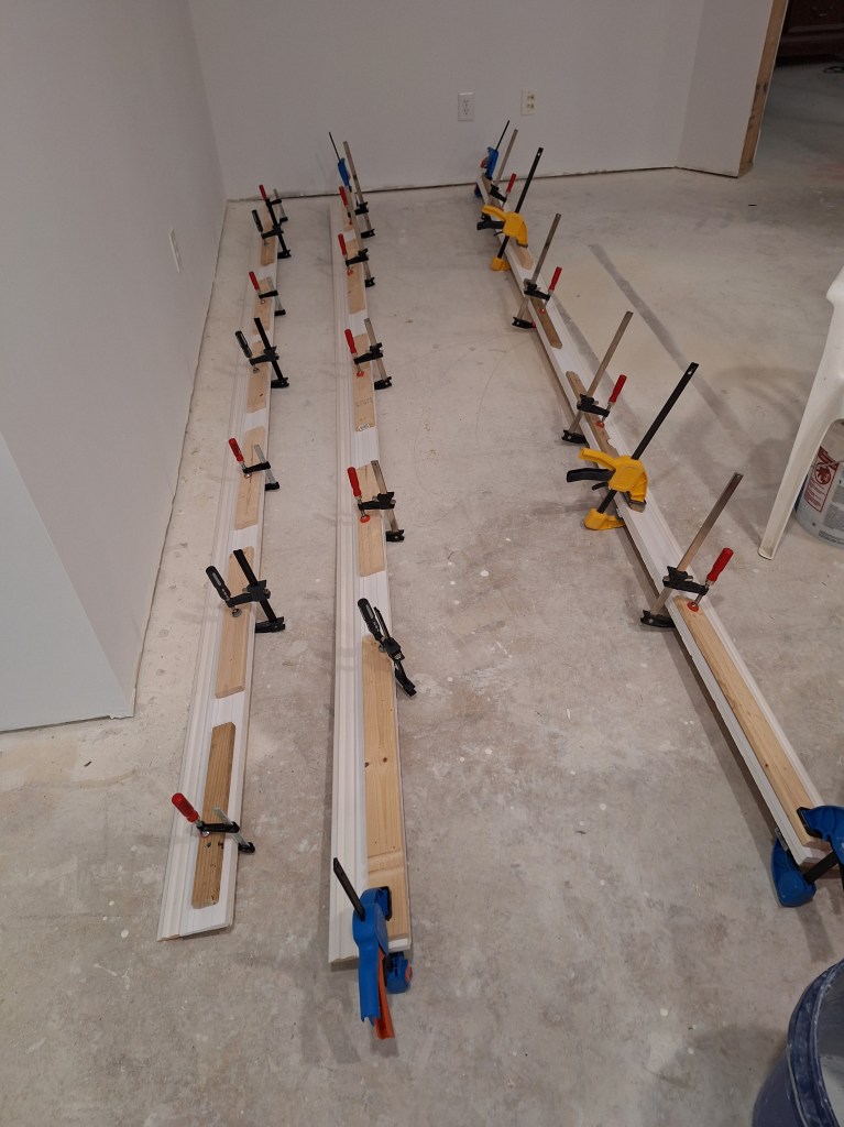
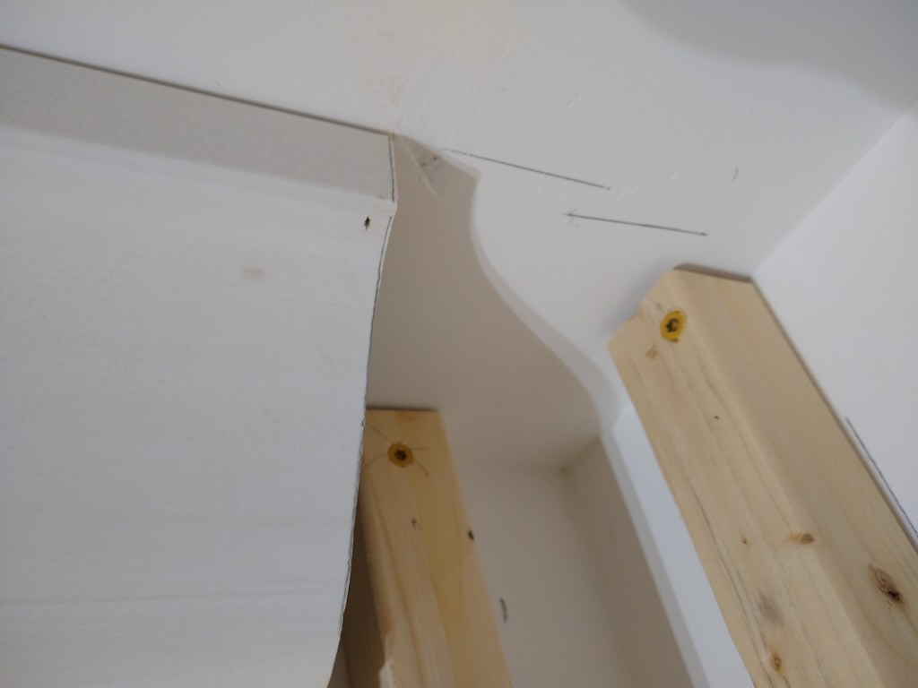
In my last post about the master bathroom, I had picked up the baseboards and glued together the two pieces that would form the whole. They were now ready to be installed. I did this along the long walls first, then went into the toilet alcove, where I had a bit of an issue that was a consequence of a poor job of tiling that area. Recall that I had to wait on new tiles to finish that area. When I got back to it, I focused my attention on making sure they aligned well enough with the existing tiles. I didn’t think about whether they were sloped or not. Unfortunately, there was a slope, and one that was too large to ignore. Even though the gaps were behind where the toilet would be, and therefore not especially obvious, I still wanted to see what I could do with them to make it less obvious. So I cut out and fashioned a couple of custom strips of wood and glued them in place to fill the gaps. Although I don’t have a “before” picture, you can see from the strip I put in, that it was not trivial.

Filler Piece Added to South Wall of Alcove
Filler Piece Added to East Wall of Alcove

Once the glue dries and they area caulked and painted, they will look much better and be virtually invisible.

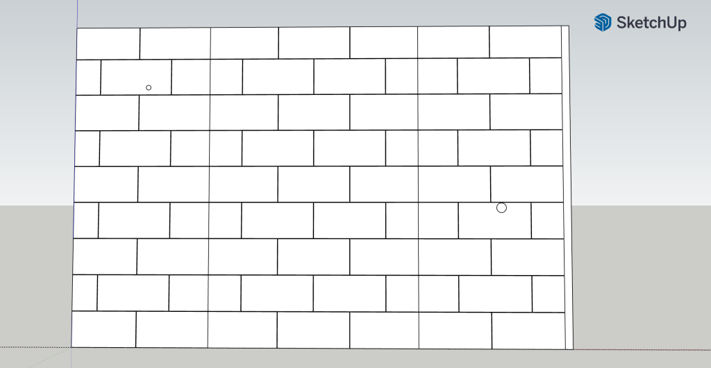
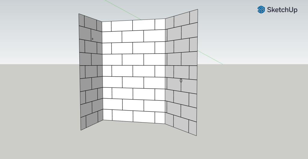
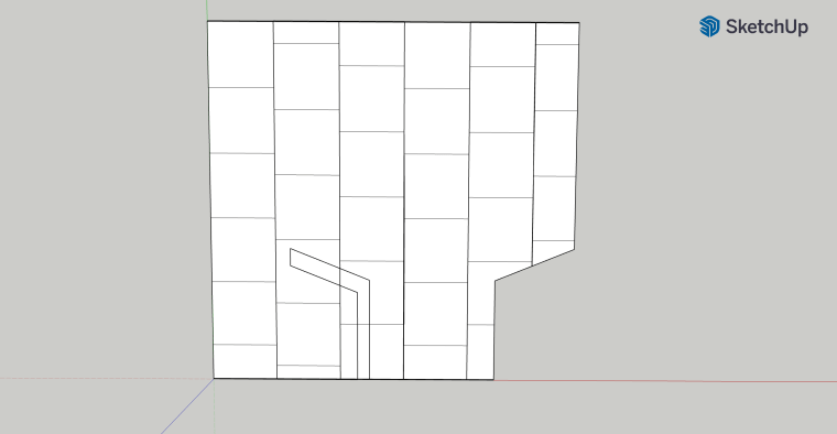
As you come out of the alcove, the wall makes a turn that produces a rather sharp outside corner. The angle here is 68 degrees. Cutting the baseboard in the usual way would make this a very pointy outside corner, and one that would be susceptible to damage. So I explored creating a three piece outside corner, kind of like what you see below.

Baseboard – A three piece outside corner.

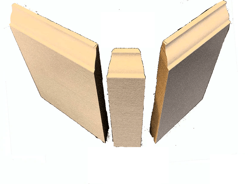
However, after many attempts and modeling in SketchUp, I could not get this to work. I believe this is because I have such a complicated profile, a more acute angle, and a sharp (not bull-nose) corner. The situation shown above is intended to deal with a bull-nose corner. It’s pretty simple because the angle is 90 degrees and most of the baseboard is flat. At least that is my sense of it. Perhaps one day I’ll figure it out. Unfortunately, I could not find anything online to show how to deal with such a situation, which made me feel like it wasn’t doable. So I needed an alternative. I decided to create an outside corner block. Kind of like this.

Baseboard – Example of an Outside Corner Block.

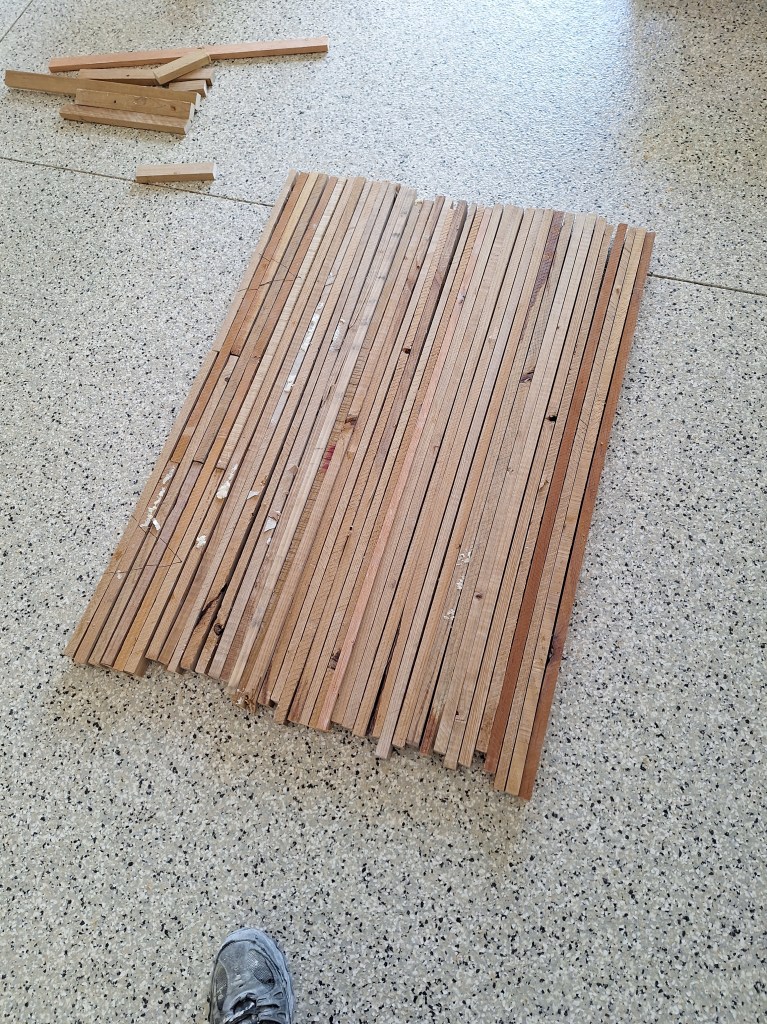
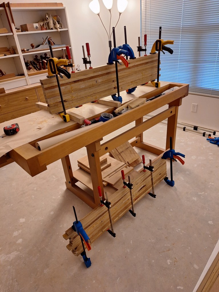
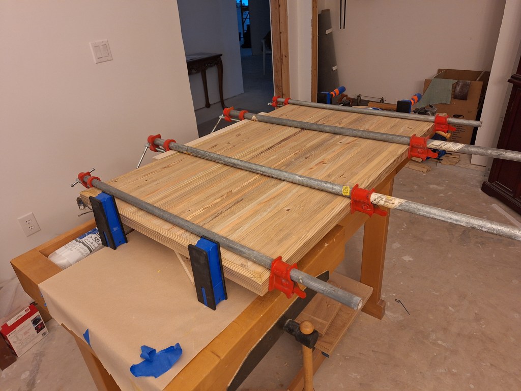
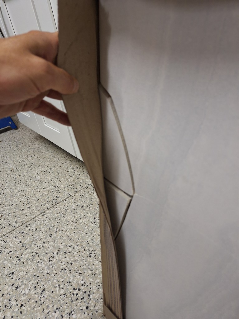
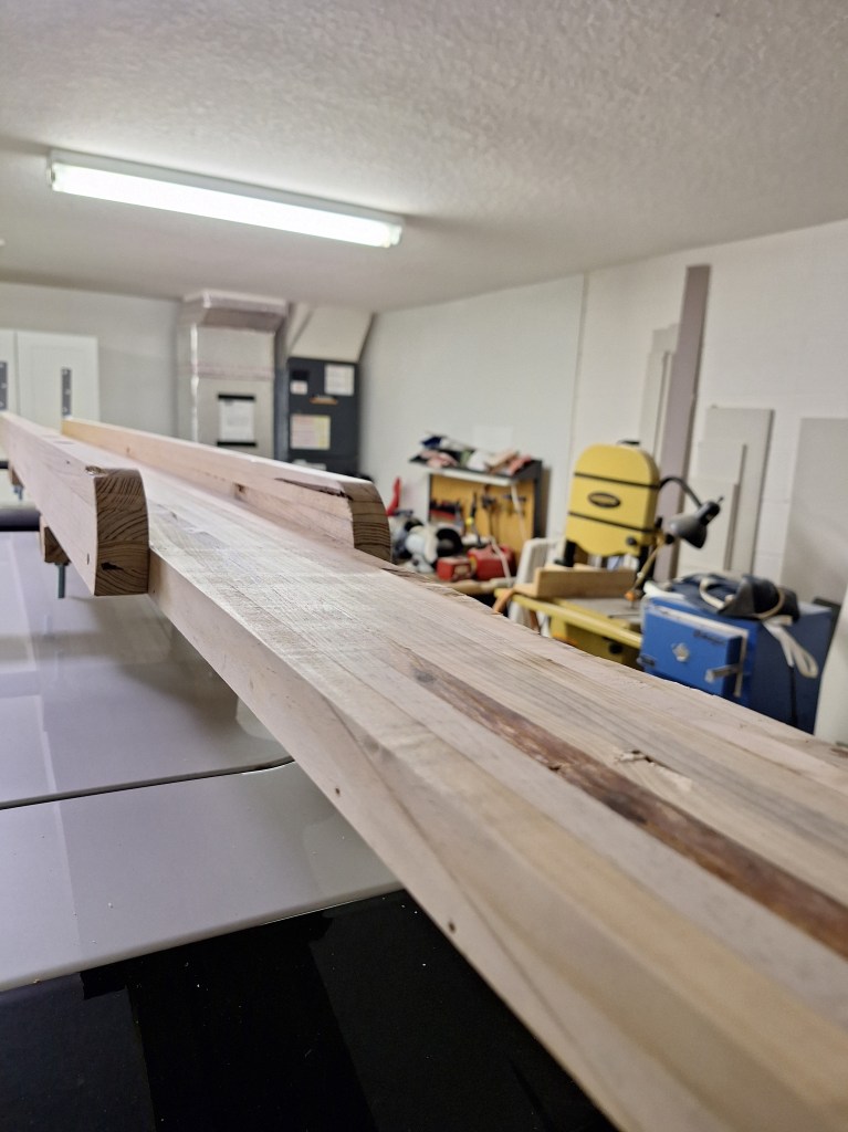
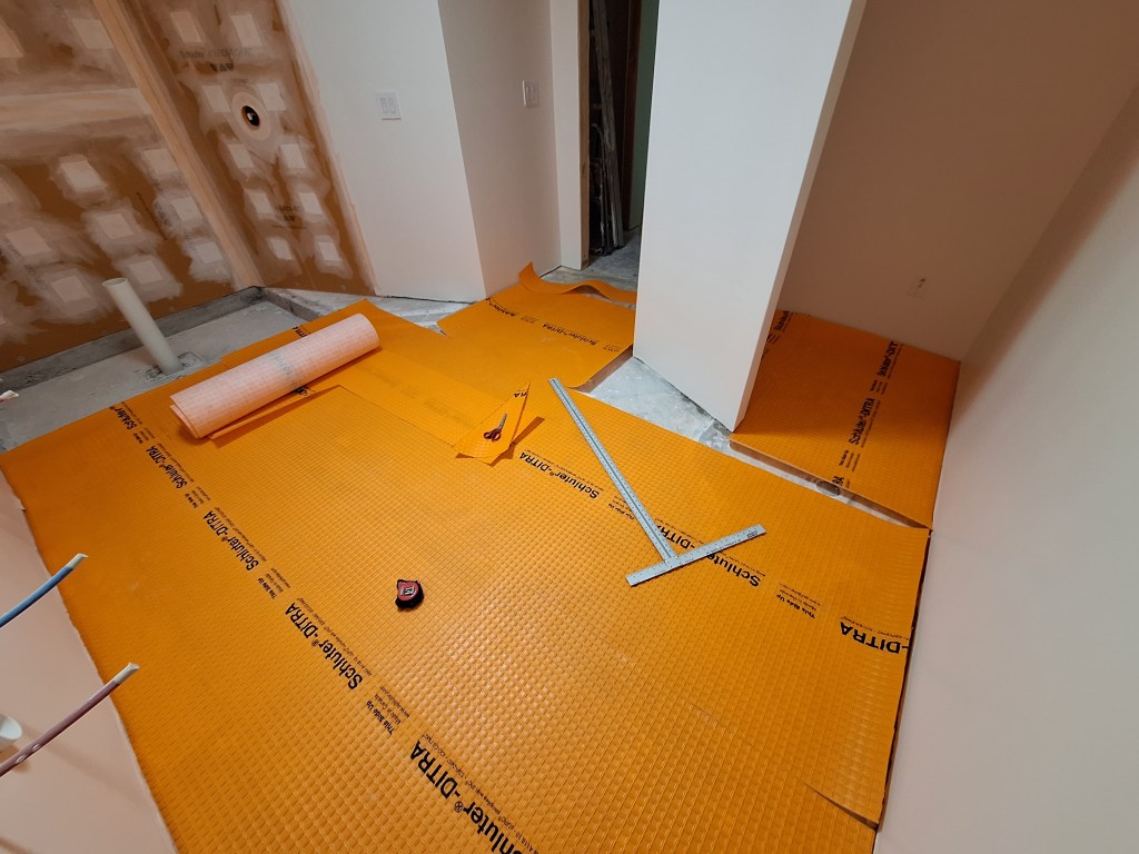
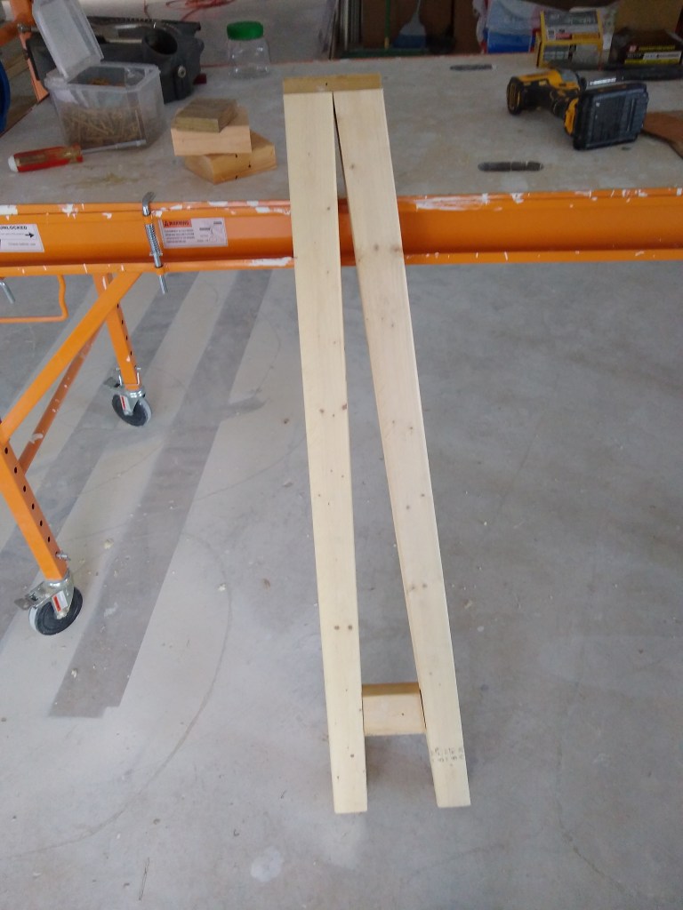
So I started building one. Here are the three pieces before gluing them together.

Baseboard – Outside Corner Block Pieces before glue-up.
Baseboard – Outside Corner Block ready for glue-up.

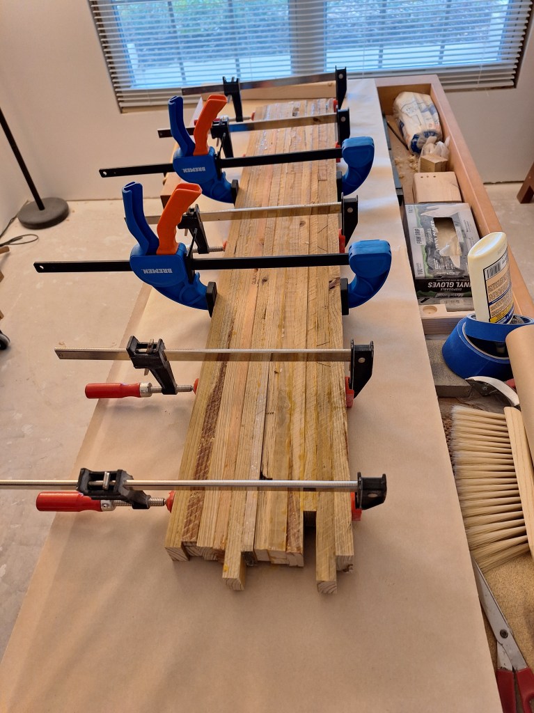
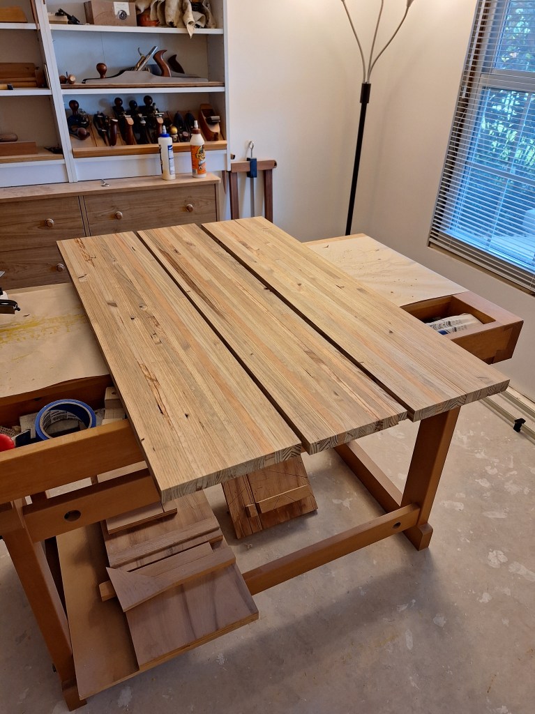
The two outside parts of the block are built up from two thinner pieces of stock in order to give them some heft. The middle piece ties them together as you can see below after I glued the three pieces together.

Baseboard – Outside Corner Block after glue-up.

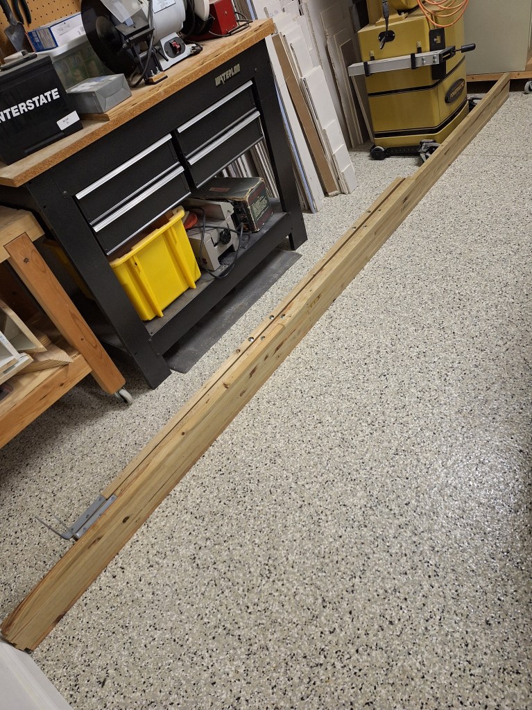
With this arrangement, I can simply butt the baseboard to the ends of this corner block. The corner block presents a flat face as you round the corner, making it more resilient to knocks. To dress it up a little, I added a decorative top using basecap. Here it is in the raw.

Baseboard – Outside Corner Block with Basecap.

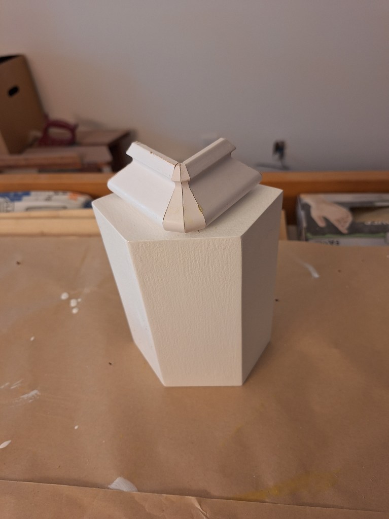
The block part is painted, but the basecap is not. In this image, I had just glued it together and placed it on top of the block. I then put it in position without fastening it to see how it looked.

Baseboard – Outside Corner Block test fit. View from inside alcove.

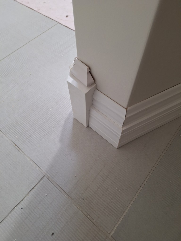
The short piece of baseboard that butts up to it in the image above is not fastened either. I just placed it there to see how it looked.

Baseboard – Outside Corner Block test fit. View from outside alcove.

The basecap is not as flush with the wall as I’d like, but it was very tricky to get those angles perfect. To get it to fit just right, I’d have to modify the angle of each of the four pieces by a small fraction of a degree. You can’t just modify one of them because the profiles won’t line up. I decided not to risk it and will let the caulking fill those gaps. It’ll look just fine.

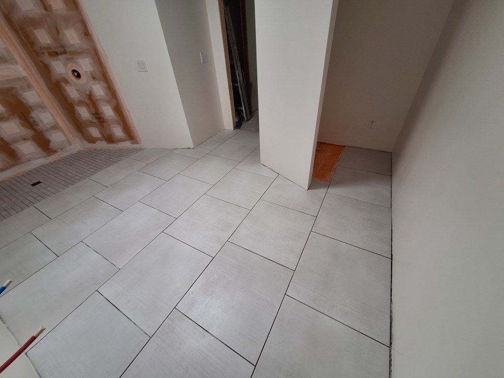
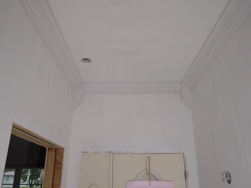
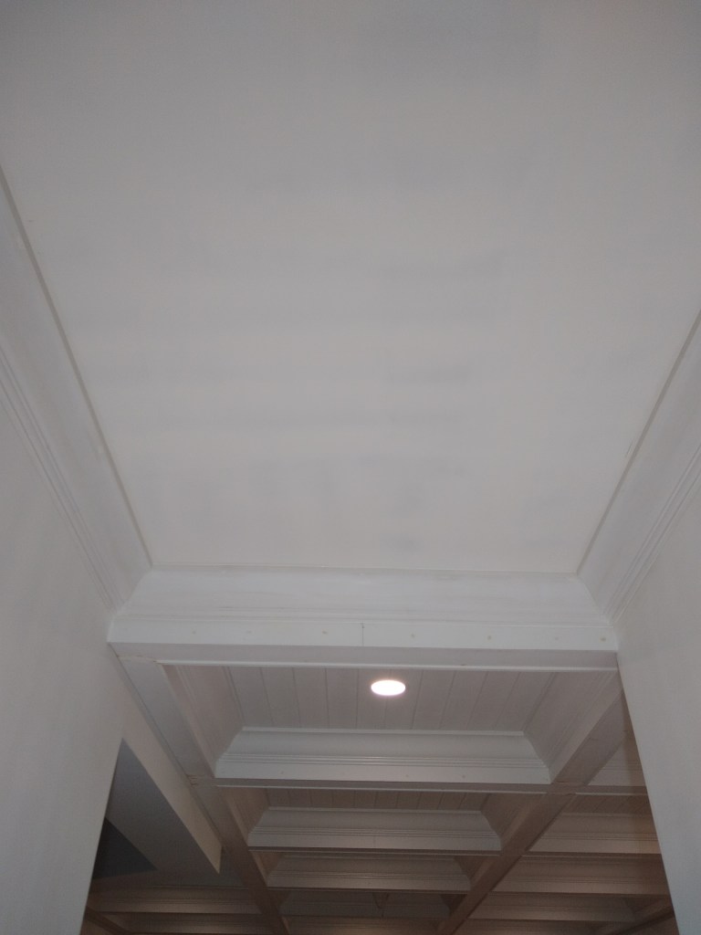
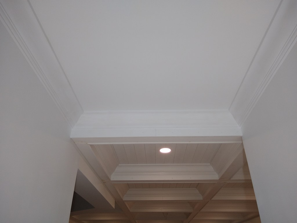
After a bit of sanding and painting, the corner block was done and I could finally finish the baseboard installation. Here are several shots from different angles.

Baseboard – From Entrance.

One could question the value in putting baseboard along the entire length of the vanity wall, since most of it will be covered up by the vanity. My vanity has legs, so if you get down low enough you can see it. So I decided just to do it.

Baseboard – Toward Entrance.

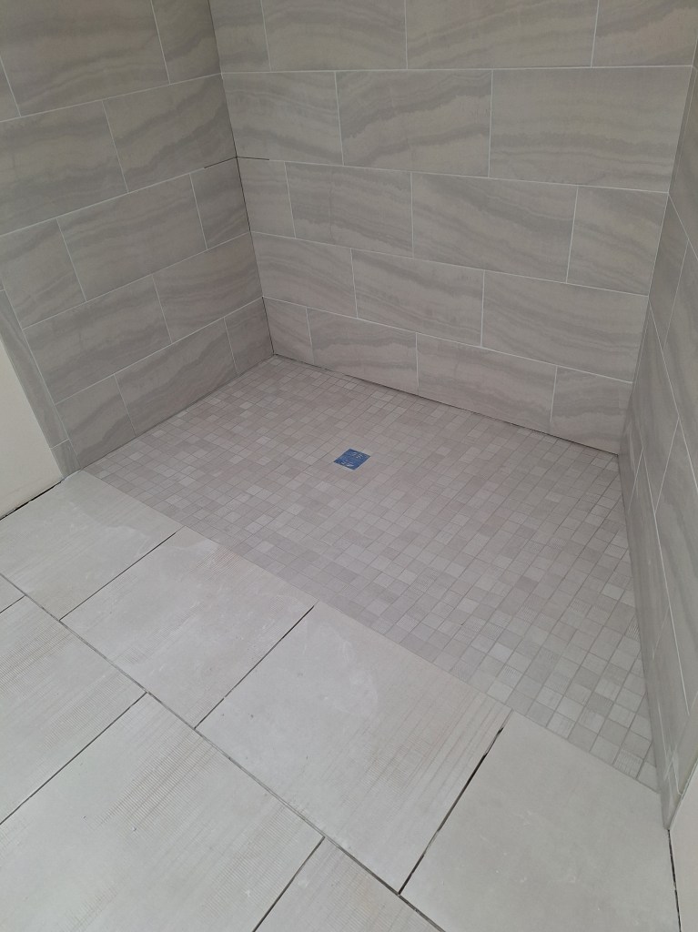
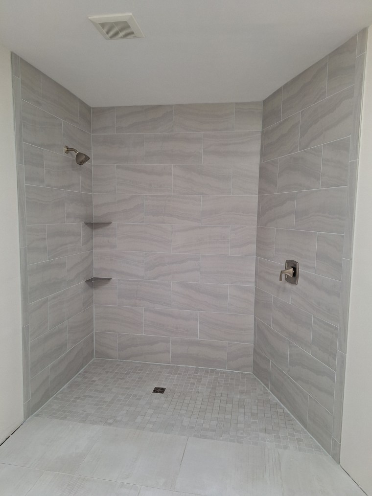
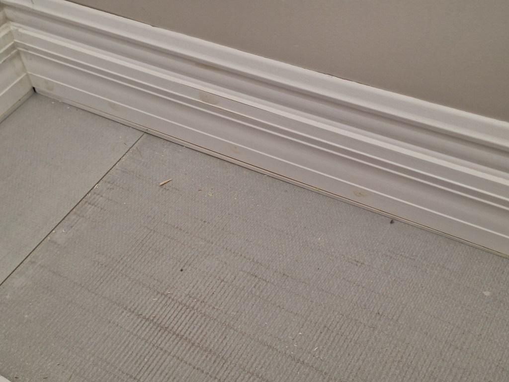
Where the baseboard meets the tiled shower walls, I added a return to terminate it nicely. Here’s a closeup of one of them.

Baseboard – Closeup of Return.
Baseboard – Toward Toilet Alcove.

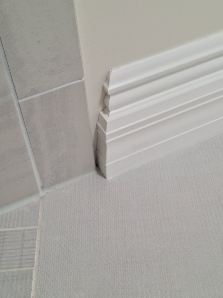
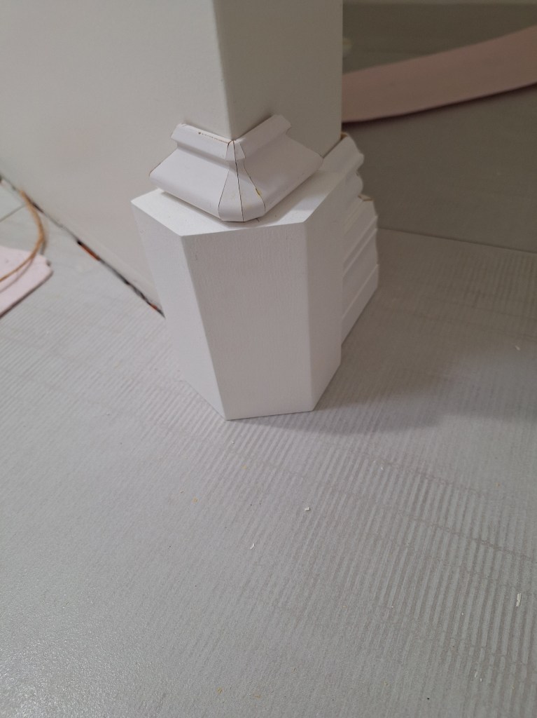
In the above image you can see the outside corner block and how the baseboard ties into it. Here are some closeups.

Baseboard – Outside Corner Block.

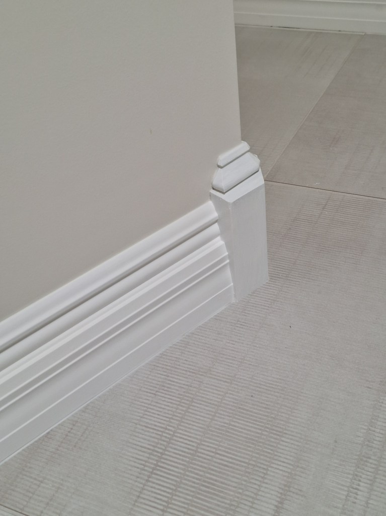
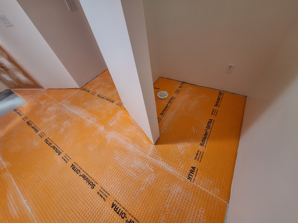
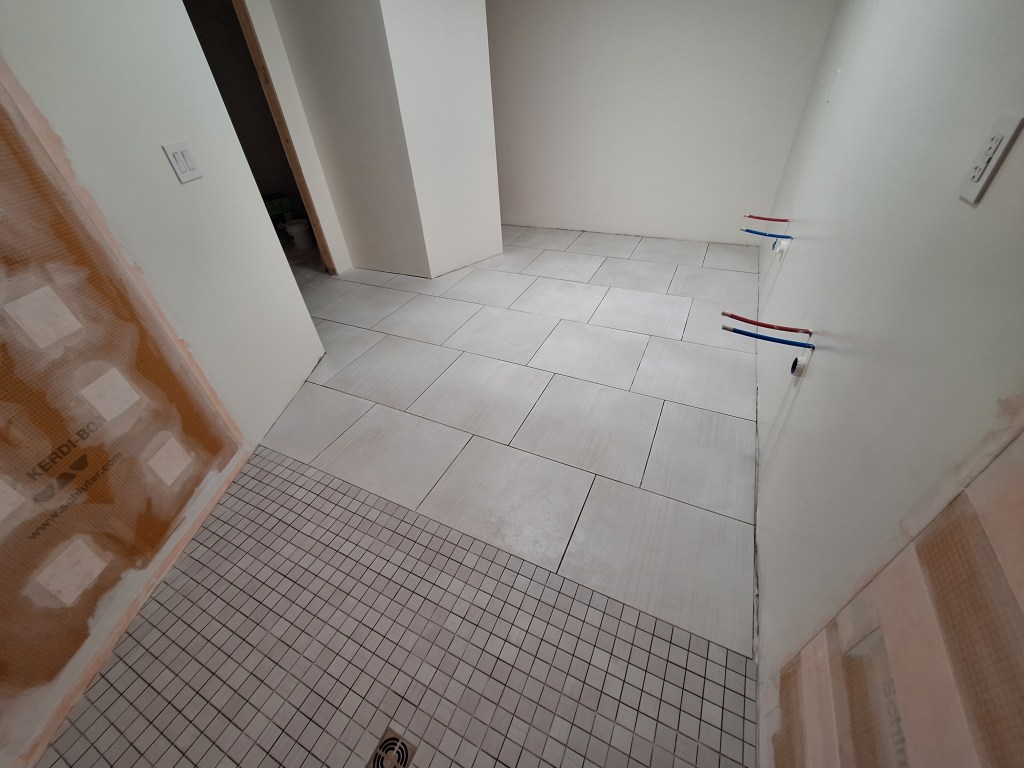
I think it looks pretty good and will stand up much better to knocks than if I’d mitered the two pieces at that corner. And here’s a look inside the toilet alcove.

Baseboard – Toilet Alcove.

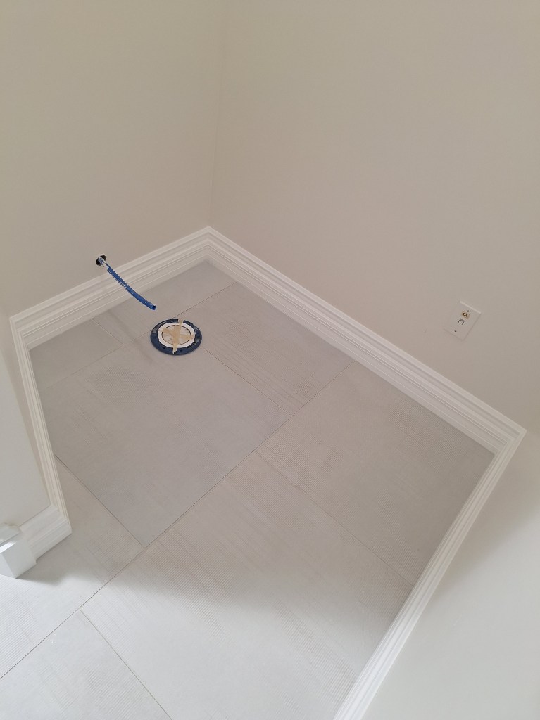
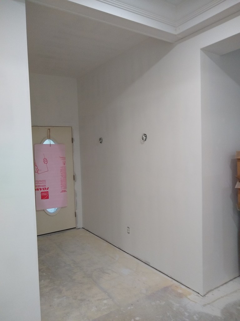
In the image above you can also see the toilet flange I had just installed in preparation for the toilet, which I did next. Here it is.

Toilet Installed.

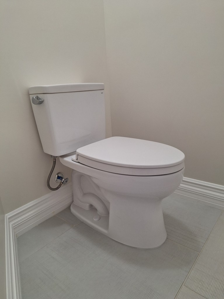
And here’s one with the seat up. Sorry, just clean water in there.

Toilet Installed.

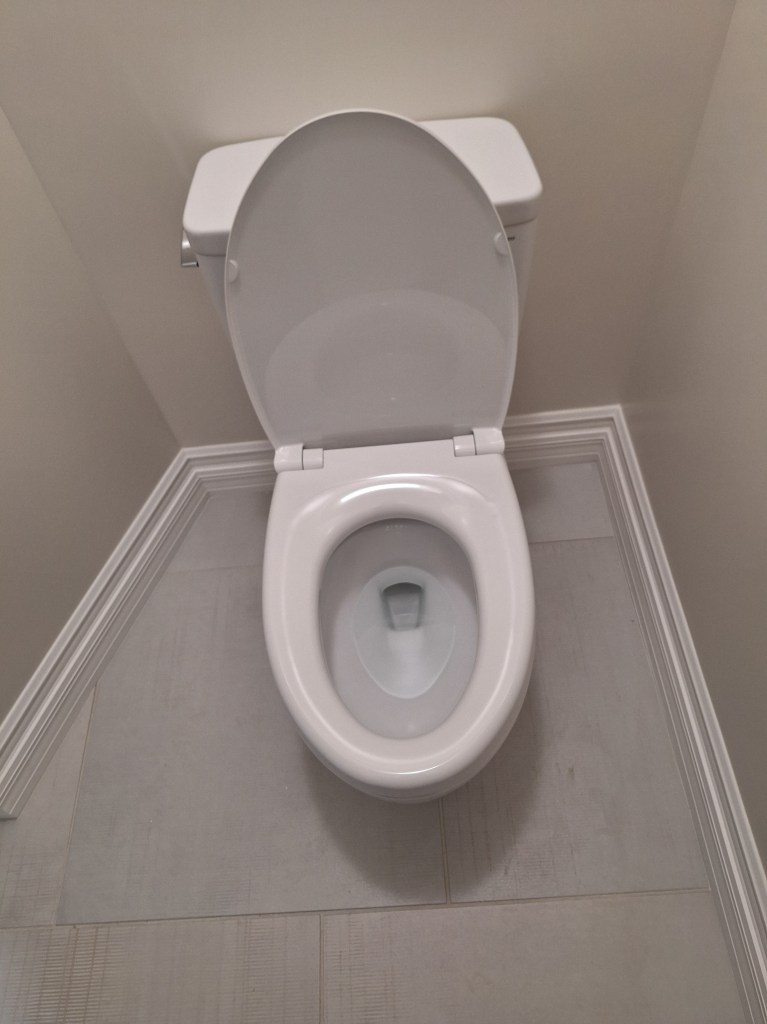
This was my very first toilet installation. It was all new to me, and I got kind of lucky with it. The toilet only just fit. The center of the toilet flange is supposed to be 12″ from the finished wall. Mine was 11 1/2″, which was a mistake due to not taking the thickness of the drywall into account. Online, some people claimed they prefer to use 11 1/2″ to get a tighter fit, which gave me some relief back when I first realized my mistake. I was hopeful I would get away with it. In the end, I did, but 11 1/2″ was not appropriate here. I had no wiggle room at all. The back of the toilet is right against the wall, and with my rather beefy baseboards, there is only about 1/8″ of clearance between the baseboard and the base of the toilet. Another stroke of luck was that the tank lid is the same size around as the tank. In my experience, is not that common. I’m used to it being larger, like a lid of a jar. Consequently the lid fits on the tank as intended.

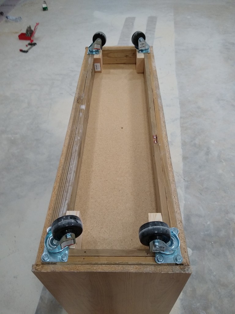
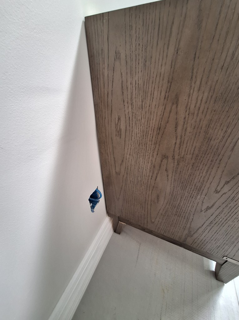
With the baseboard done and the toilet installed, I could now move the vanity into place. Upon doing so, I discovered that I could not push the vanity right up to the wall. The back legs were directly inline with the back of the cabinet rather than inset. Consequently, the thickness of the baseboard prevented it from lying flat against the wall. There was about an inch gap.

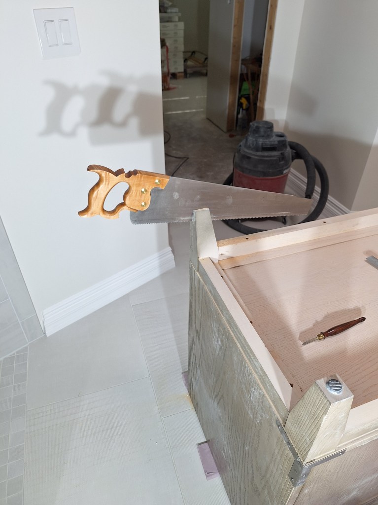
I turned the vanity upside down on the floor to explore my options. I was hoping the legs would come off and that I could reposition them, but wasn’t optimistic about that. Since the vanity is quite heavy and would require very sturdy legs, simple screw-in legs were unlikely, which was what I discovered. I also considered cutting the baseboard just enough to let the feet slide in, but I wasn’t keen on that. The baseboard should not need to accommodate the vanity. One day I may decide I want to change it out for another one. In the end I decided to modify the back legs of the vanity to accommodate the baseboard. So I marked out what I wanted to cut, and got started.

Modifying Vanity Back Legs – Start the Cut.

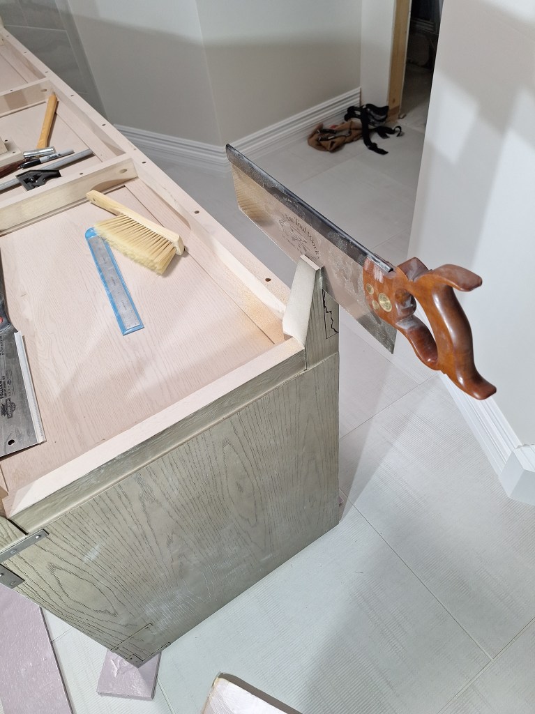
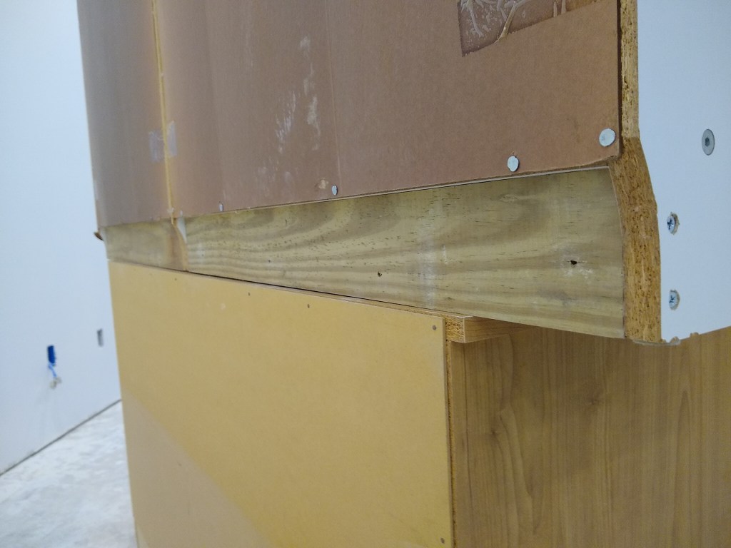
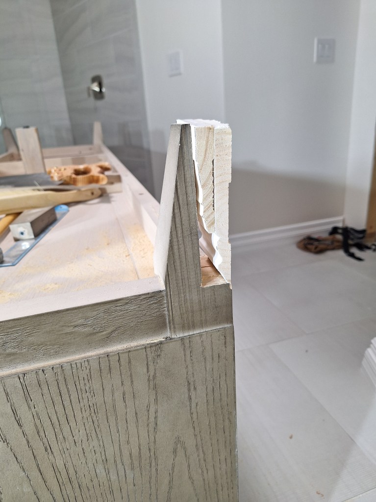
In the image above you can see how I traced out the baseboard profile in order to minimize what needed to be cut (keep in mind it is upside down). I wanted to preserve as much of the foot as possible, which wasn’t very much. I started my cut with a back saw, but had to complete it with a panel saw because the plate of the back saw could not take it all the way. The image below is of the other leg.

Modifying Vanity Back Legs – Panel Saw used to complete the Cut.

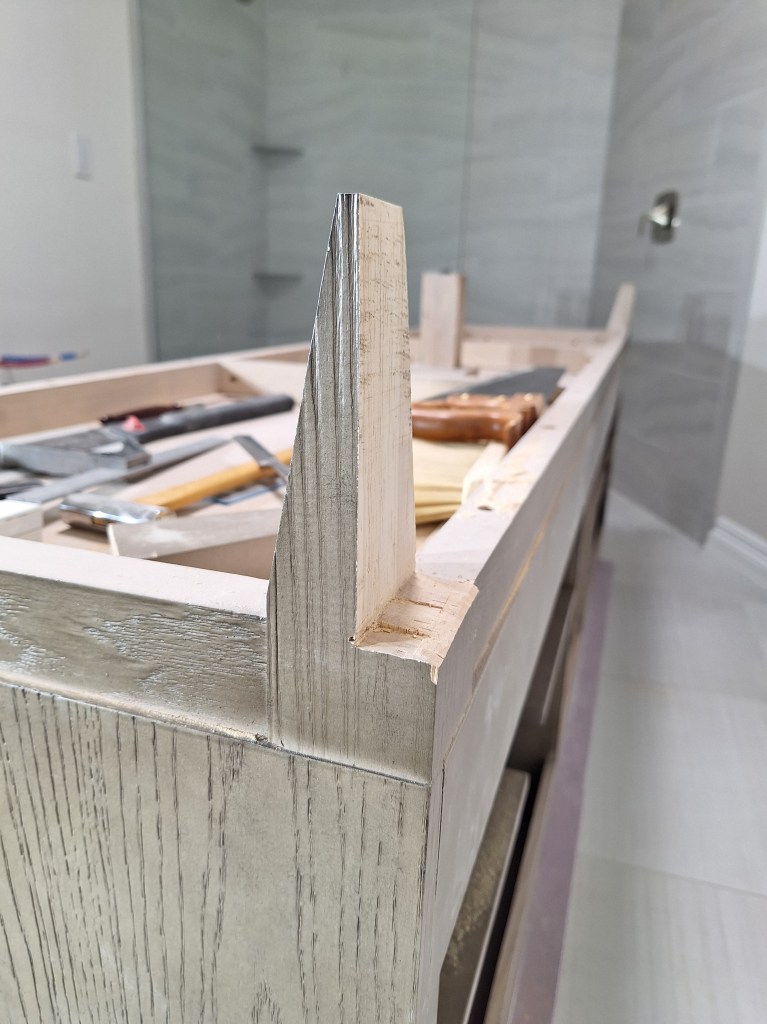
Once the cut was complete and cleaned up a bit with a chisel, it looked like this.

Modifying Vanity Back Legs – Cut Complete, side view.
Modifying Vanity Back Legs – Cut Complete, back view.

Here is a shot with a piece of baseboard held up to it so you can see how it fits.

Modifying Vanity Back Legs – Baseboard Test Fit.

There will be a screw-in pad under the leg, so there is plenty of room for the baseboard.

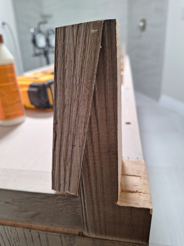
Although the back legs look like stiletto heals, they are quite strong. They are made of solid wood, so once the vanity is in place, it would be well supported with just that amount of wood. However, I would be less confident if it was moved around a lot. So I decided to use the off-cuts to bolster them. Each leg received the off-cut of the other in order to keep the finished side out. Although you have to go out of your way to see these legs, this makes them less conspicuous should you try.

Modifying Vanity Back Legs – Bolstering, show side.
Modifying Vanity Back Legs – Bolstering, hidden side.

These were attached with glue and brad nails, which was plenty. However, I decided to add a wedge to fill the gap, just to be extra careful.

Modifying Vanity Back Legs – Support Wedge.

Although the support wedge is a different color, it is set in a bit, so from above it is not visible.

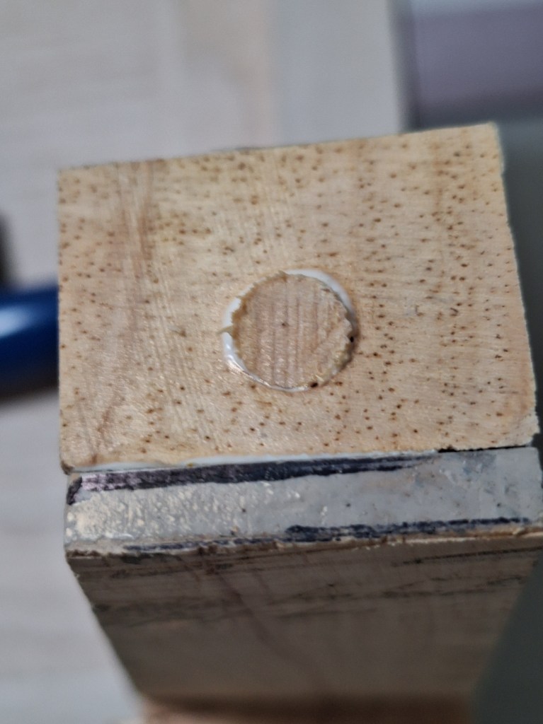
I then plugged the hole at the bottom that would receive the plastic pad. I couldn’t simply reuse the existing hole because it was angled. So I glued a dowel in and let it sit overnight before drilling a new hole that would go straight down.

Modifying Vanity Back Legs – Plugging hole for Plastic Pad.

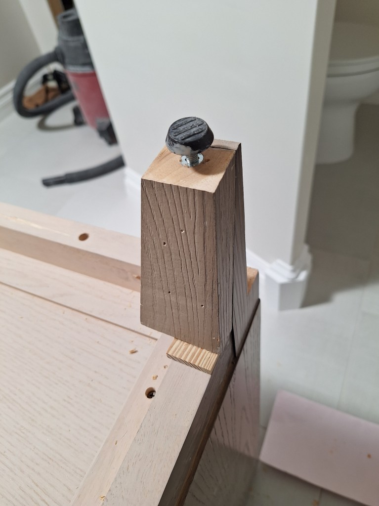
The new hole was then drilled and the threaded insert put into the hole, followed by the plastic pad.

Modifying Vanity Back Legs – Plastic Pad Added.

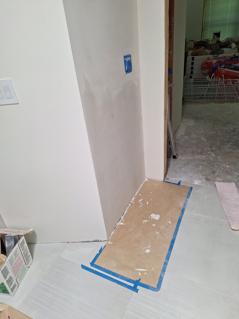
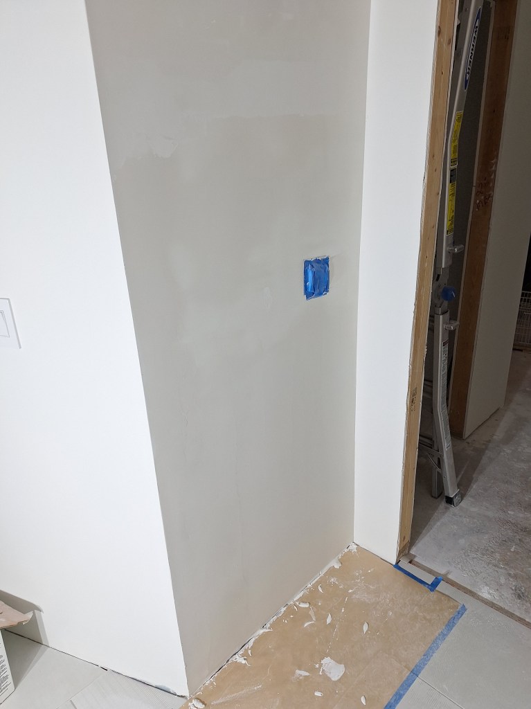
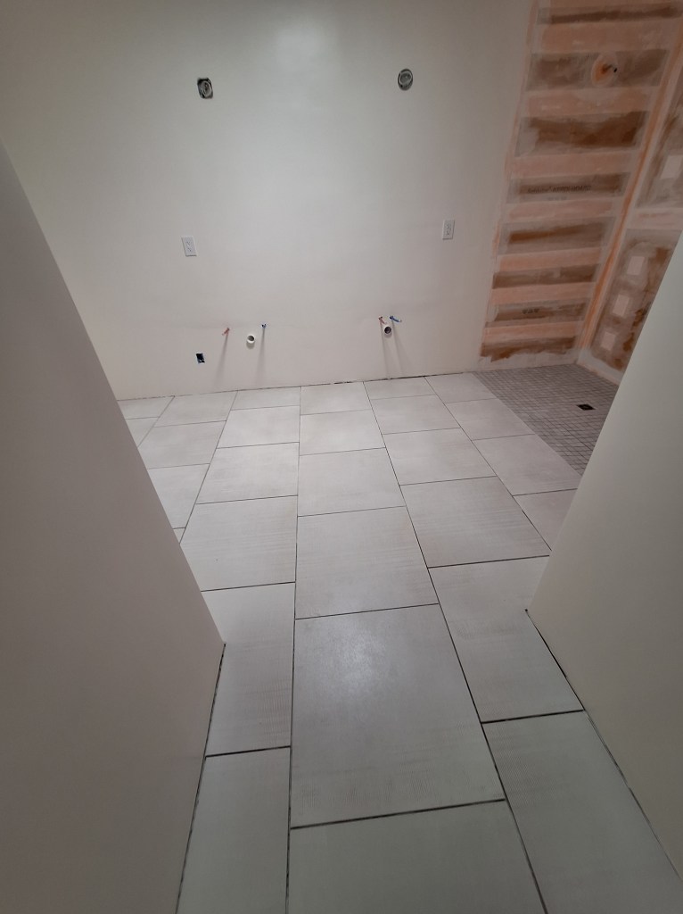
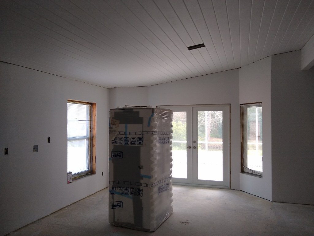
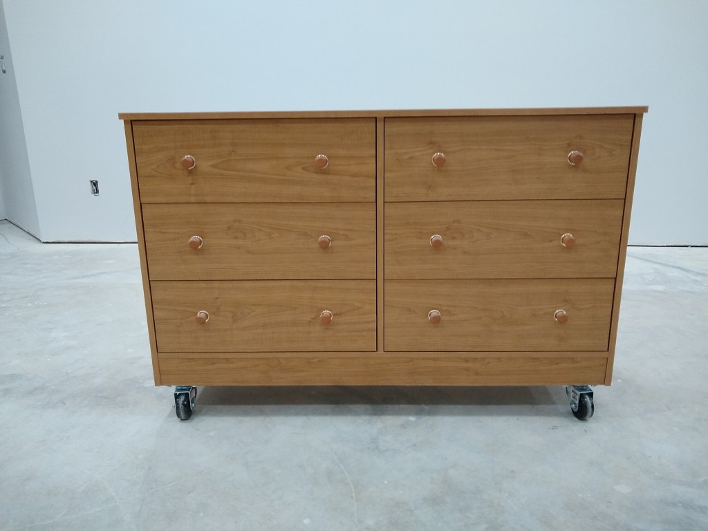
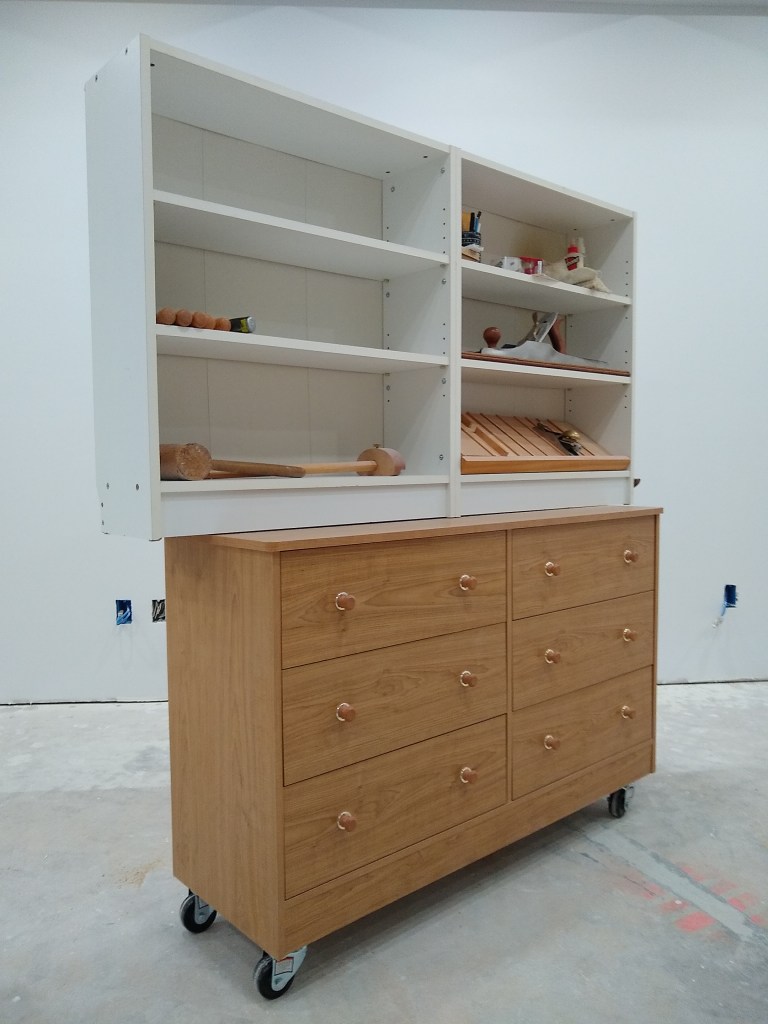
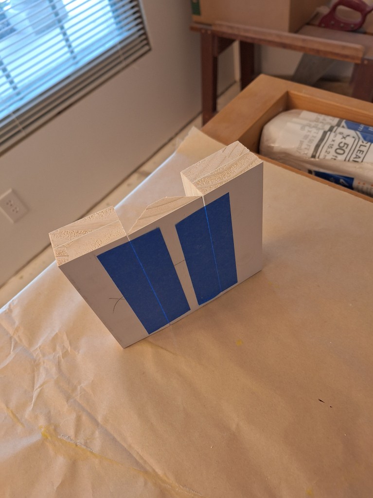
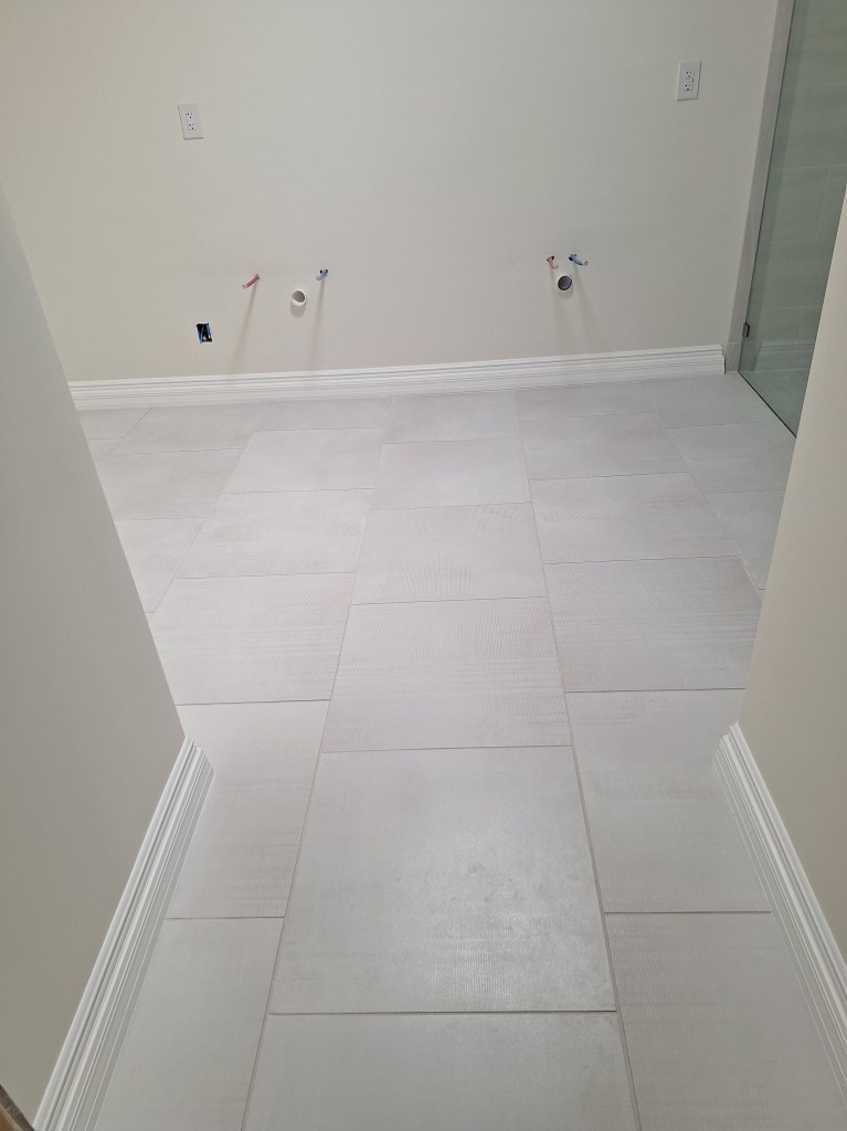
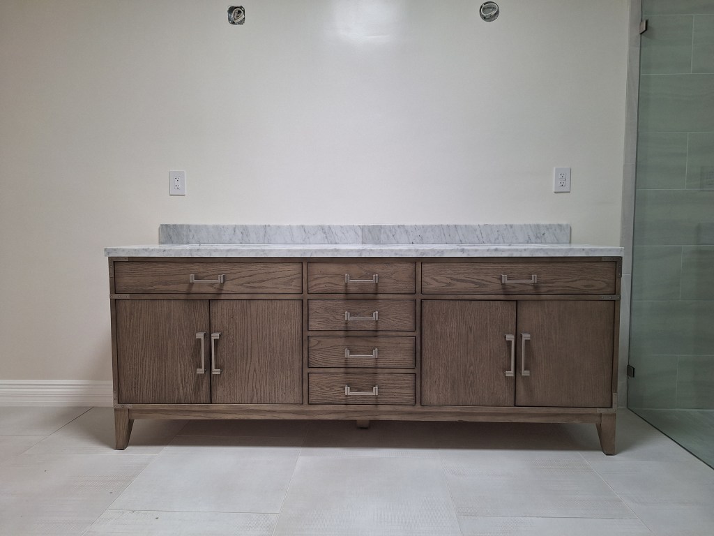
After both pads were added to the modified legs, I was able to move the vanity cabinet into its final location.

Vanity in Place

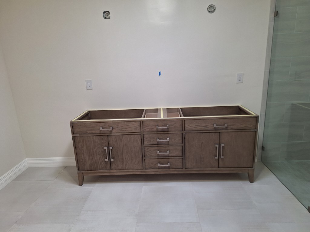
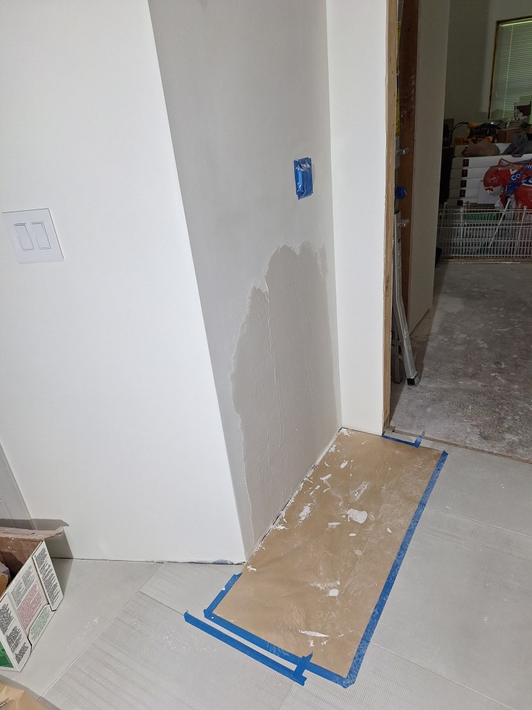
The blue tape on the wall marks the center between the where the vanity lights will go. It is now sitting flush with the wall, as you can see below. The vanity will not be fastened to the wall. It will simply sit against the wall like a dresser in the bedroom. It’s very heavy, especially with the marble top, so I am not concerned about it shifting if it is knocked.

Vanity now tight to the Wall

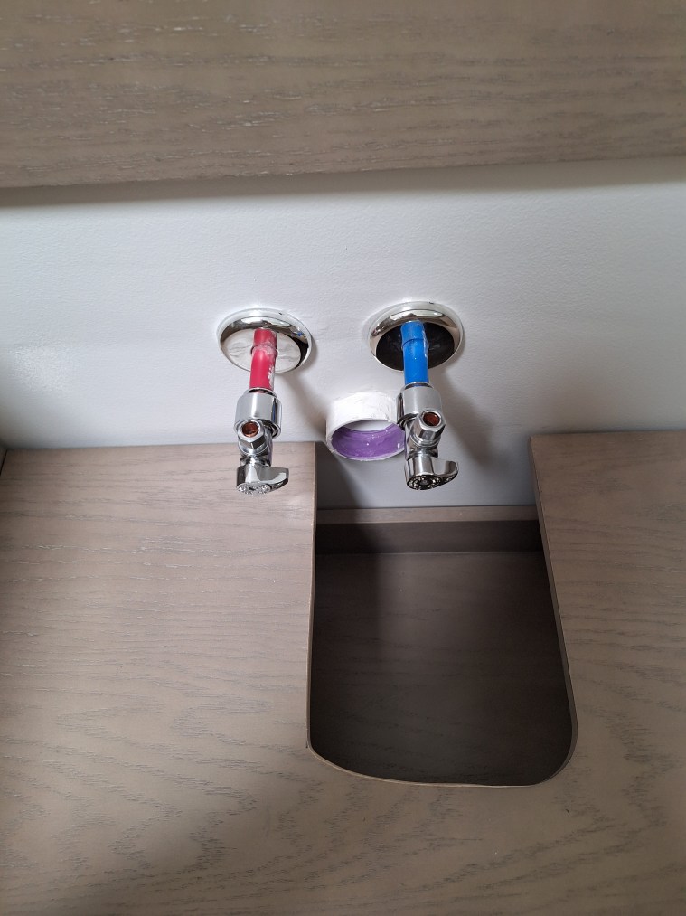
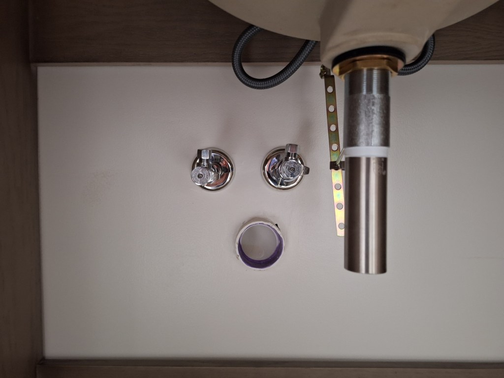
I also added the angle stops for the sink supply lines.

Angle Stops for Left Sink

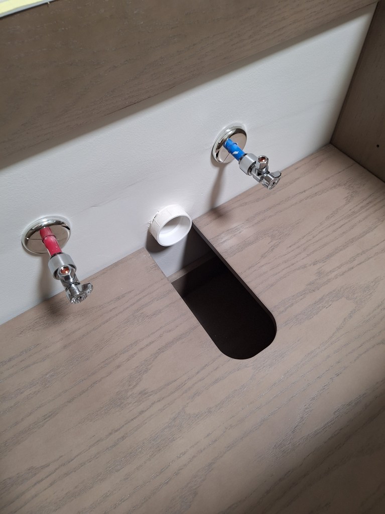
I had to widen the opening in the shelf below the right sink to make room for the the drain.

Angle Stops for Right Sink

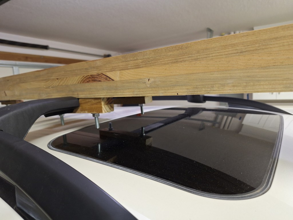
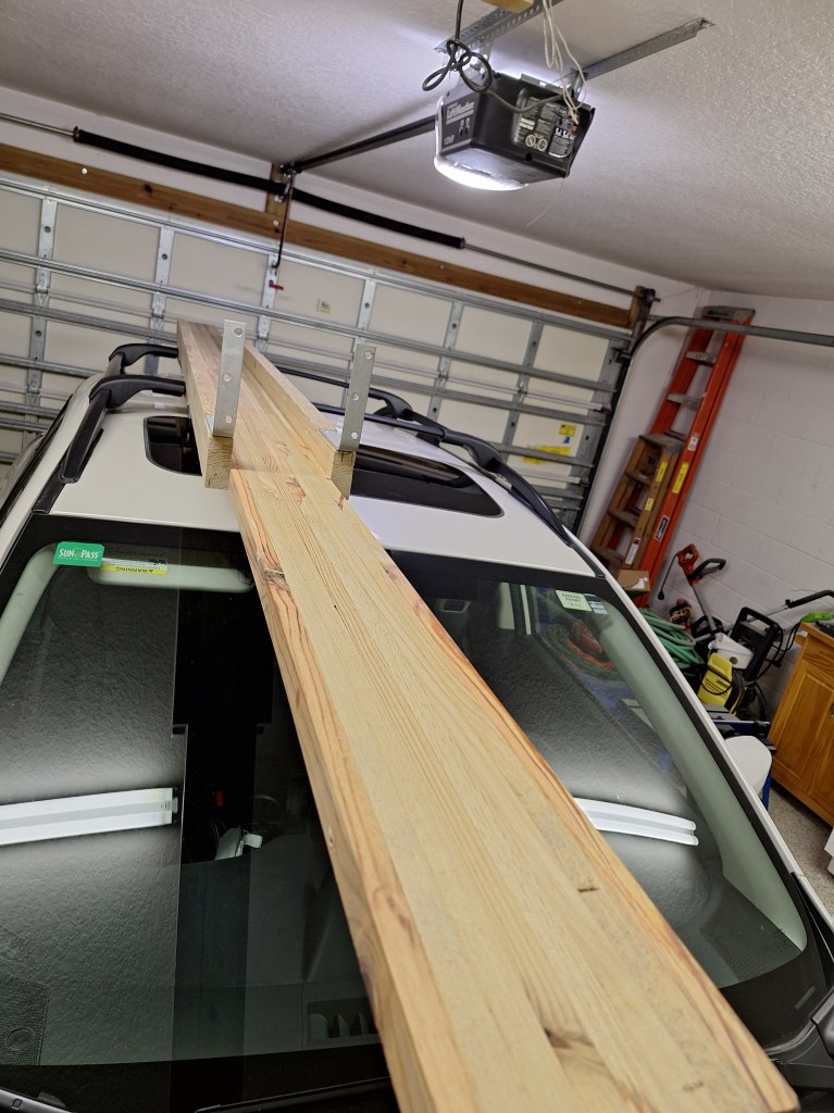
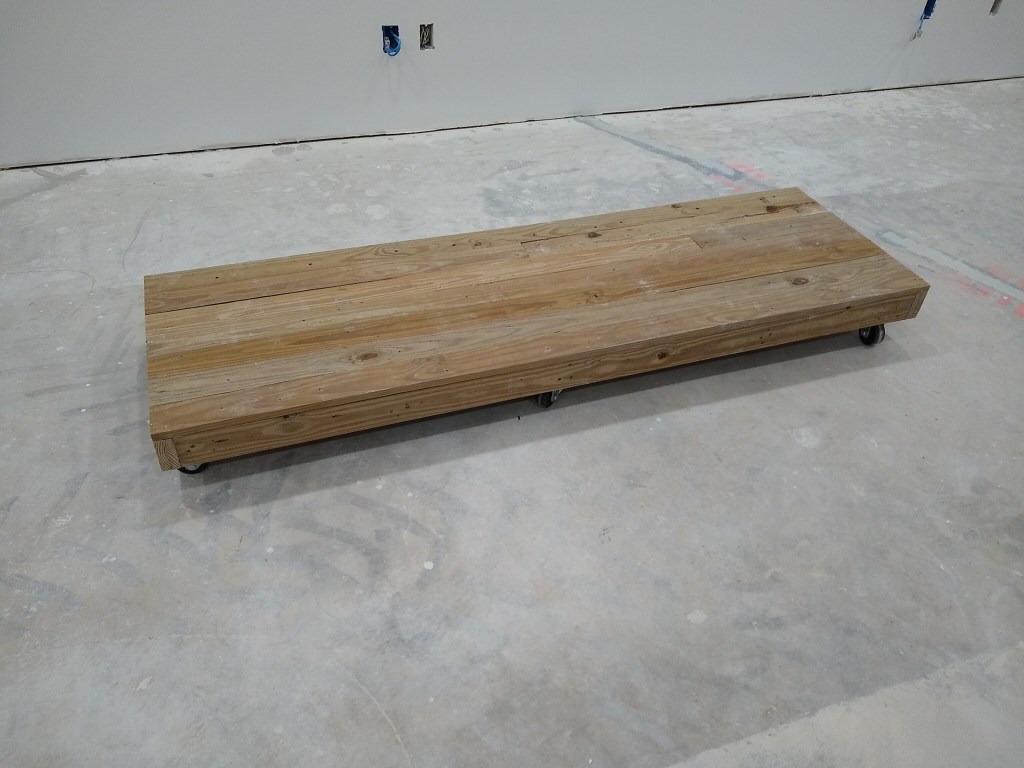
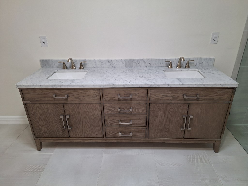
The next task with respect to the vanity, was to put the marble top in place. It is a massive thing and something I could not do on my own. With the help of a couple of neighbors, we managed to put it in place.

Marble top Installed

The backsplash came in two pieces that simply butt together. Unfortunately, one of them was not quite square, so when I pushed them together, there was a gap. I used my angle grinder to straighten it, after which they came together nicely. I used silicone to secure it to the marble top, then applied a bead of silicone at the seem between the top of the backsplash and the wall. That should hold it. I didn’t want to apply silicone to the back of the backsplash to adhere it to the wall because I wanted to minimize any damage to the wall should I choose to change out the vanity some day. If I ever did need to remove the backsplash, the bead of silicone between it and the wall would only require minimal repair to the drywall, if any.

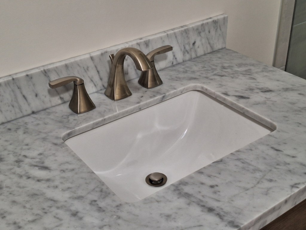
The faucets were added next.

Faucets Installed.
Closeup of Faucet and East Sink

After that, the drain and supply lines needed to be hooked up.

West Sink Before Hookup
West Sink After Hookup
East Sink Before Hookup
East Sink After Hookup

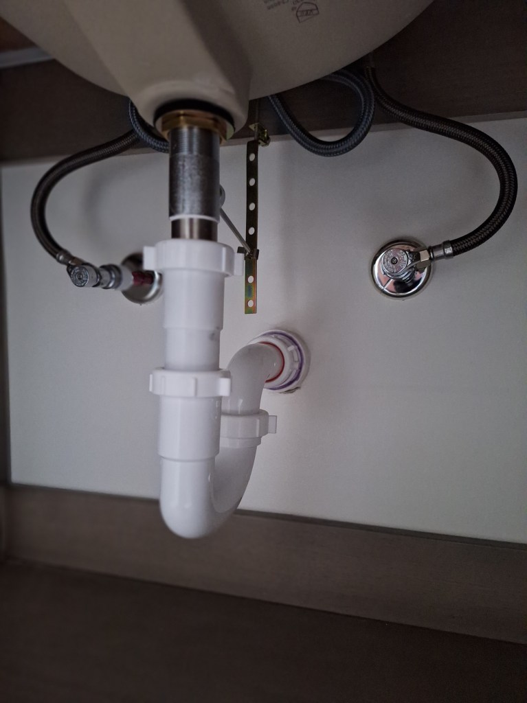
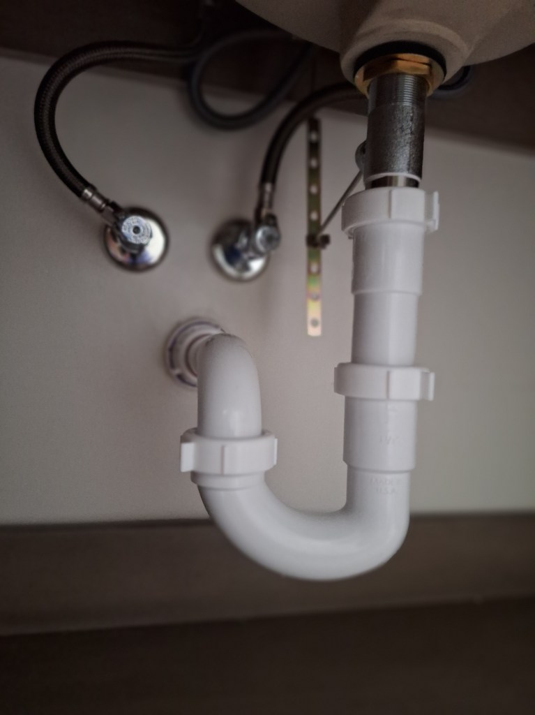
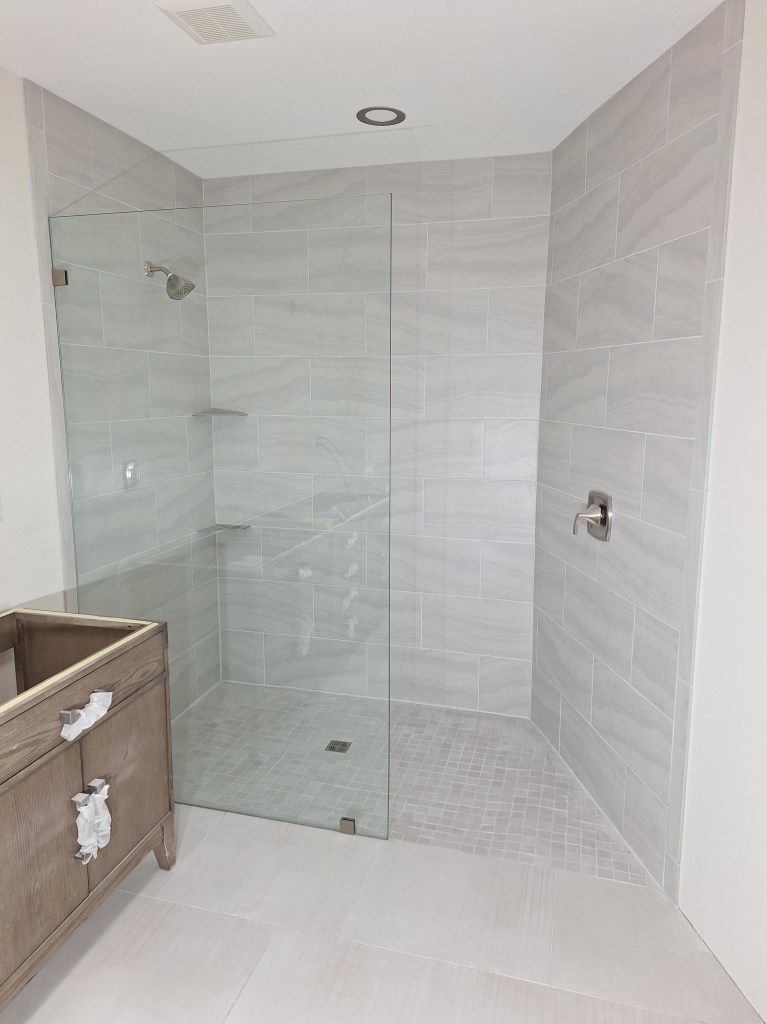
With that done, I now have a functioning bathroom. The vanity lights and mirrors still need to be added, along with other bits and pieces (like towel rods, etc.). At the moment I’m not sure whether I want to have a single large mirror or two smaller ones. Decisions like this can be made much later, even when I’m living in the house, so I will put them off so that I can start work on the guest bathroom.

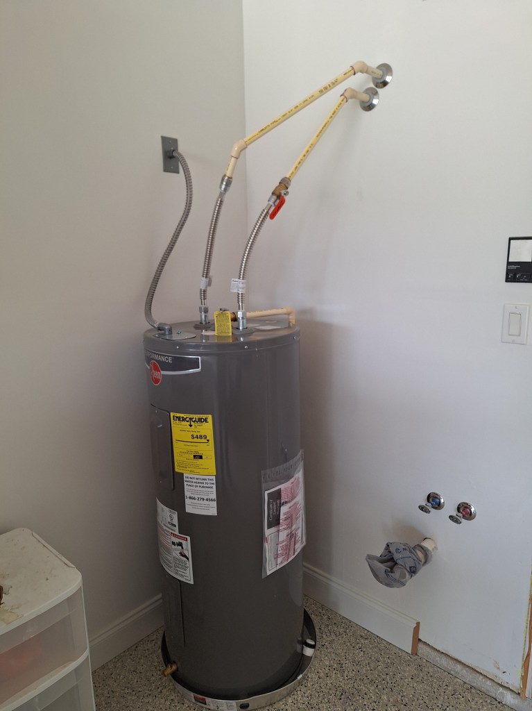
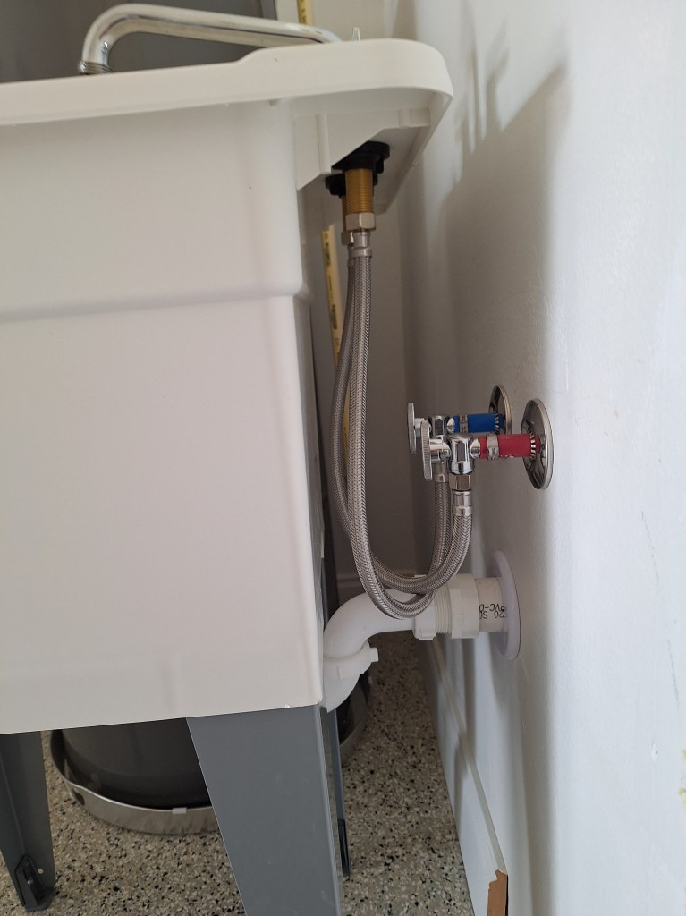
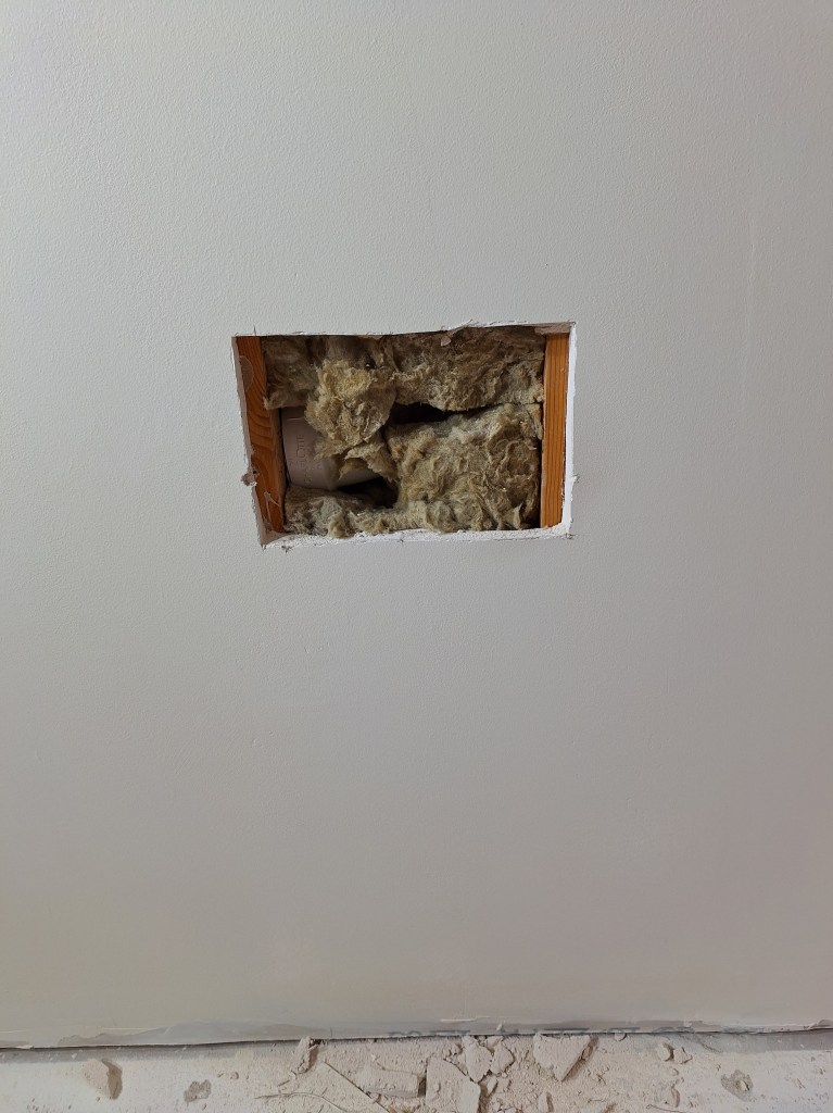
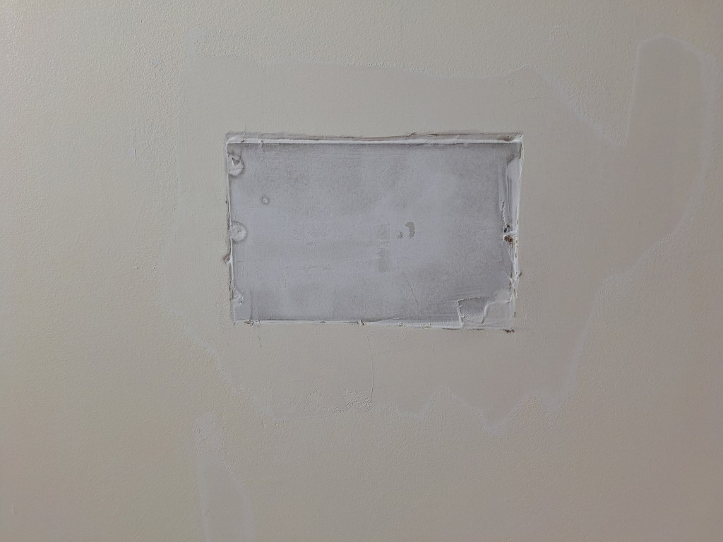
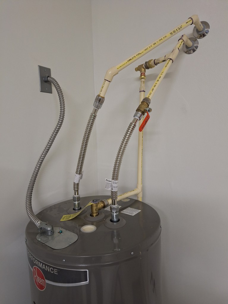
One more thing before we go. In the June/July post I talked about installing the hot water heater. At that time I had not yet had my work inspected. During this month I had the inspection done, but failed. I needed to add a pressure relief valve between the main supply line and the hot water heater. I was under the impression the relief valve that came with the tank was sufficient, but the inspector informed me that it was for relieving pressure when the temperature was too great. The valve I needed was to relieve pressure when the water pressure from the city fluctuates. That is, at different times of day it can change. An adjustable pressure relief valve is needed to keep the pressure consistent. So I have since installed it, as shown below.

PRV Installed
PRV Closeup

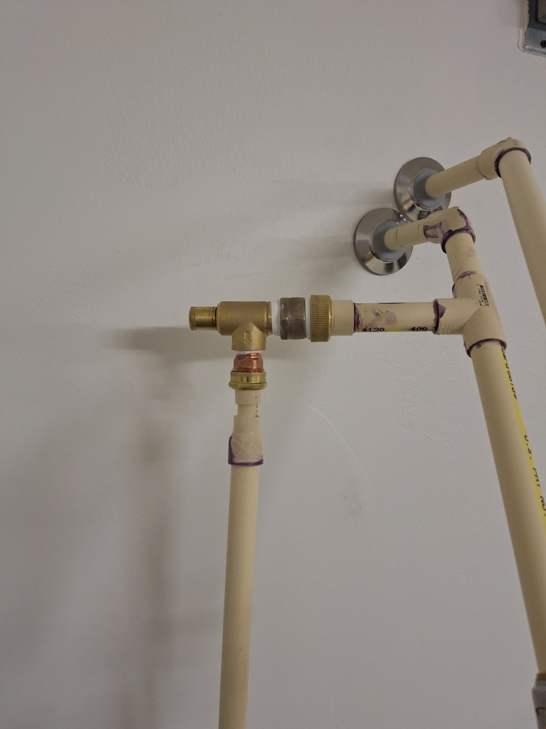
As you can see, I tee-ed off the main cold water line (purple primer everywhere). The PRV has a dial at the top of it (left in the image above since the valve is installed on its side) that is used to adjust the pressure to what you want. If the pressure exceeds that, the excess will flow out the line going down and out of the garage.

This was just inspected, and I passed. So on to the guest bathroom.

Drafting Table Top – September 2024

Since I was no longer driving toward a mid November move in date for the house, I decided to indulge myself with another side project. I actually started this while working on the wall repair in the master bathroom I documented in the last post, but did not complete it until this month, so I chose not to mention it in the August post.

When I was in high school I built a drafting table.

Drafting Table – Original Top.

The top was made from particle board with a solid wood edging and covered with a thin green vinyl sheet. I currently use it to support my computer monitor and keyboard. It is sufficient, but the vinyl covering is not very flat anymore. In the image above you can see the “bubbled” areas by the mouse. I have managed with this, but is a bit of a nuisance. Here is another view from the front.

Drafting Table – Original Top.

I was thinking of replacing the vinyl cover, but then I got the idea that I could build a new top from the remaining furring strips I had lying around in the garage, making a kind of butcher block desktop. Since the job of fixing the bowed wall at the entrance to the master bathroom required that I wait for each application of drywall mud to dry overnight (see the July/August post), I used the extra time to start on it. Here is a shot of the furring strips I would use. I had just cut them to rough length. They are not arranged in any particular order yet.

Drafting Table Top – Pieces cut to Rough Length.

The top needed to be less than 45″ wide to fit in the space I had, and I wanted a depth of around 26″. The dimensions weren’t that important, so I kept those numbers in mind, hoping I had enough material to get close. Maximum yield was what was really driving the dimensions, as long as I didn’t go over the 45″ width. As you can see from pieces on the left in the image above, I didn’t have enough full length pieces to make the depth I wanted, so I had to introduce six rows of two-piece strips to get to about 31″, knowing that I would plane a good bit off in preparation for glue-up, which would hopefully leave me with around the 26″ I was looking for.

Drafting Table Top – Beginning Glue-up.

Before glue-up I had to pull a lot of staples and a few nails and screws from these boards. Remember, they used to be attached to concrete blocks (using nails), were covered with an insulating material (attached using staples), and had drywall screwed into them. Once they were “clean”, I could run them through the thickness planer to smooth out the faces that would be glued together (what you see above). After planing, the depth was reduced to about 25″. Since my thickness planer can only accommodate 13″ wide boards, I divided the stack of strips into three sections, each no more than 9″ deep and organized them in a way that looked aesthetically pleasing. I distributed the lengths that were composed of two pieces evenly among the full length strips and marked them so I could maintain their relative positions.

During glue-up I further subdivided each section into two in order to make the glue-up more manageable. This is shown above. Once each of these subsections was cured, I glued them together, which is what you see below.

Drafting Table Top – Combining the two Subsections to create the first Section.

I left the glue to set overnight. The next day I pulled off the clamps and ran it through the thickness planer to get it close to final dimensions, then squared off the ends.

Drafting Table Top – Cleaned Up on Thickness Planer.

The final thickness would be established once I did the same for the the other two sections. Once they were taken to the same state as what you see above, I would run all three through the thickness planer, one at a time, to ensure they were of the same thickness before gluing the three sections together. Here are the other sections in clamps, ready to set up overnight.

Drafting Table Top – the other two Sections glued up.

And here they are after running them through the thickness planer, making them all the same thickness.

Drafting Table Top – Three Sections Planed to Thickness.

Since the combined width is greater than the capacity of my thickness planer, extra effort was needed to ensure they aligned properly as I brought them together. To help with this, I used dowels, referencing their location relative to the top (show) face.

Drafting Table Top – Dowels used to align the three Sections.

Then it was time to apply the glue and clamp the three sections together.

Drafting Table Top – Glued and Clamped.

The next day I removed the clamps and scraped off the glue that squeezed out from between the seems. I also place a straight edge across the top to see how flat it was. As you can see from the image below, there was significant cupping. This was largely due to my forgetting to place clamps at the seems. A stupid mistake that resulted in far more hand planing (see below) than should have been needed.

Drafting Table Top – Cupping

Although this does not have to be perfectly flat, I had to do something about this. So I pulled out my number 7 jointer plane and got to work.

Drafting Table Top – Removing the Cupping.

This took considerable effort, leaving plenty of shavings on the floor.

Drafting Table Top – Many Shavings to Flatten Top.

In the end, I didn’t get all of the cup out, but I got it to a state I was comfortable with. To flatten that extra bit where the light shines through (see image below) would require the removal of so much more material that it wasn’t worth it. This would be fine.

Drafting Table Top – Cupping mostly removed.

And here it is after completing the flattening work.

Drafting Table Top – Flattening Complete.

Although it looks pretty good here, I still had a couple of things I wanted to do to it before applying a finish. In order to have no end grain showing I would put an edge around it with mitered corners. I would also use an epoxy resin to fill in any holes. These boards were pretty rough at the start of this, so there were plenty of nail holes, screw holes, and imperfect edges. After the milling process and the hand planing, some of these things were cleaned up, but others were exposed. Using an epoxy resin with a color tint would get it to the state I wanted. But first, I added a solid wood edge around it with mitered corners.

Drafting Table Top – Edging Clamped in Place.

The next day the clamps were removed and I cleaned it up using hand planes and a sander in preparation for the epoxy.

Drafting Table Top – Prepped for Epoxy.

I thought it was looking pretty good at this stage, and I hadn’t even applied any finish. Here are a couple of additional shots.

Drafting Table Top – Prepped for Epoxy.

With the solid wood edge added, the final dimensions came out to 43 3/8″ by 26 3/8″, which is right in line with what I was after. So I took that lovely looking thing you see above and did this to it.

Drafting Table Top – Epoxy Applied.

At this stage it looks like I’ve spilled coffee all over it. But that is just part of the process. The bits that overflowed the areas I intended to fill will be planed and sanded away after the epoxy has cured. Here is a closeup of an area.

Drafting Table Top – Closeup of freshly applied Epoxy.

The epoxy comes clear, but I added bronze mica powder and a bit of black to tint it. I’m happy with the color. The next day I planed then sanded it, then added a second application to a few areas that needed it. Once that was cured, I planed it off and sanded it all in preparation for finishing. Here are a couple of shots of it ready for finish.

Drafting Table Top – Ready for Finish.

To finish this, I decided to use shellac. I’ve not used shellac before, but have heard a lot about how great it is. So I bought shellac flakes and mixed up only enough for this project. Shellac has a shelf life, so I did not want to buy it premixed, since whatever was left over would almost certainly go bad before I’d be ready to use it elsewhere. I took a picture of the surface as I was just starting to apply the finish so you could see the difference.

Drafting Table Top – Finish Being Applied.

Here it is after finishing the first coat.

Drafting Table Top – First Finish Coat Applied.

It certainly darkened it a bit. I think I preferred the color before the finish, but not enough to redo it. Shellac dries very quickly, so you can put another coat on almost immediately after you have finished applying the previous coat. I put two coats on the hidden side, just so it was sealed, and eight coats on the exposed surfaces. I did not specifically choose to apply eight coats. That was what it took to exhaust the amount of shellac I mixed up. I was aiming for around ten coats, so eight was close enough. After the final coat of shellac, I gave it a light sanding with 320 grit sandpaper then applied a coat of paste wax to make it nice and smooth. Here it is after that.

Drafting Table Top – Finish Complete.

And here it is installed.

Drafting Table Top – Installed.

Yes, the base color does not match the top at the moment, but I will refinish the base one day after I’ve moved into the house. For now, this will do. Here are a couple of “after ” images that correspond to the “before” images at the start of this post.

Drafting Table Top – New Top.

I’ve been updating this post as I went along in this project, but it is only on this last update that I’ve been able to do it on my new desk top. I am very happy with it. My mouse has a much flatter surface to move over and I love having the extra space. This was a fun project, and I look forward to doing more of this kind of thing (woodworking, as opposed to construction) once I’m settled in the house.

Master Bathroom – July/August 2024

Having put on hold the work on the master bathroom while I waited for my shower wall tiles to arrive, I shifted my attention to the great room and adjoining areas, as described in the previous post. But now it was time to pick up where I left off in the master bathroom.

The shower wall tiles had been sitting untouched during most of the time I was painting the main areas of the house. However, I took the step of unboxing them as soon as they arrived to make sure they were intact before setting them aside. There were three broken tiles, and I communicated that to the distributor. However, I ordered a sufficient amount that I didn’t think replacements would be needed. Here is one of the pictures I sent to the distributor showing the broken tile, still in the box.

Broken Shower Wall Tile

The tiles are 22″ x 11″. To be precise, they are 22 1/4″ x 11 1/8″. The precision is needed when modeling the layout in SketchUp. In the model, I even account for the 1/8″ grout lines. I learned this lesson when I worked on the large floor tiles in the master bathroom, which I described a couple of posts ago.

Here is my first attempt at layout. This is a 2-D rendering, so you have to use your imagination.

Shower Wall Tile Layout – First Attempt in 2D.

In this image you can see three wall sections. The one on the left represents the wall with the shower head that is 90 degrees to the adjacent back wall. Note the small circle in the top portion of that section. It represents the shower arm that is currently in place. The back wall is the middle section, and the section to the right of it is the angled wall, approximately 45 degrees to the back wall. The rightmost section is where the shower valve control resides, and I’ve represented it with somewhat larger circle, depicting its location on the wall.

In this layout, I simply staggered the tiles, bisecting the ones below. They are centered on the back wall and extend out. What this revealed was that I would be left with a narrow strip on the right side, as you can see above. That won’t do, so I had to try something else.

My next attempt brought into consideration the location of the shower arm and the valve. In the first try, I made no attempt to account for them. Although they are close, they are not centered on their respective walls. That is due, somewhat, to the framing, but I was thinking more of utility when placing them. The shower arm is lined up with the drain, which I had no intention of moving, and I located the valve a bit closer to the entrance to make it easier to reach. Given that, I thought I would try laying out the tiles so that they were centered on these things. Here is the result.

Shower Wall Tile Layout – Centering on both Shower Head Wall and Valve Wall.

In this layout you can see two areas where we have slivers: the right side of both the shower head wall, and the valve wall. Note that I shifted the tiles up a row so that now the bottom row of the back wall starts with four tiles instead of three. I did that in order to reduce the number of slivers from five to four on the adjacent walls. I want to avoid introducing slivers as much as possible.

I can eliminate the slivers on the shower head wall by abandoning the notion of centering the tiles on the shower arm.

Shower Wall Tile Layout – Centering on Shower Head Wall Abandoned.

This is an improvement with respect to slivers, and I think it looks fine even though the tiles are no longer centered on the shower arm. However, I was unable to come up with a solution for the slivers on the valve wall. That wall is just a bit too wide to avoid them altogether. Below I show it in three dimensions. From this perspective, I feel the slivers become less noticeable since they’re in the corner. Consequently, I decided to go with this layout.

Shower Wall Tile Layout in 3D

The first step in bringing this to life was to protect the shower floor tiles with a cardboard covering and to install ledger boards above the bottom row of tile to set a reference.

Ledger Boards Installed

The reason one installs ledger boards is to create a perfectly level reference surface from which to start. I used a laser level to mark the walls before screwing these boards in place. The screws do puncture the waterproof membrane, but once the ledger boards are removed, I will fill them with a product called Kerdi-Fix, which is meant to seal such punctures. Another reason you start putting down the row of tiles above the bottom row, is because the bottom row (and, usually the top row) are unlikely to be perfectly level. When you return to place the bottom row of tiles, they will likely have to be scribed to ensure they fit well with the shower floor tiles.

I began the process by placing tiles on the back row. Here are the first tiles I placed before running out of thin-set.

Shower Wall Tiling – First three rows.

Good thing I put that cardboard down to protect the shower floor tiles. What a mess I made! Below is a closer look.

Shower Wall Tiling – Closer look at First three Rows.

All those red things are tile levelers. They screw onto plastic clips that are placed behind the tiles to pull them to the same level. After the thin-set dries, you knock them off will a rubber mallet and the plastic clips are supposed to break along a perforation. Unfortunately, it often doesn’t break cleanly, so there is usually some tedious cleanup work to remove the bits that remain.

In the closeup above you can see that for the row sitting on the ledger board, there is a wider gap between the center tile and the tile to its right versus that of the one to its left. When placing the tile to the right, I couldn’t figure out why it was not lining up correctly. Something was off. When I pushed it toward the center tile, the gap on the top closed before the bottom. This suggested that the ledger board was not level, even though it sat exactly on the laser line over its entire length when I installed it the day before. Could the tile edge not be flat? I doubt it. Perhaps the wood moved overnight. I brought it in from an unconditioned garage into a conditioned house, which could have resulted in some movement. With the thin-set on the wall, I did not have time to mess with it, so what I ended up doing was opening the gap wider than I wanted in order to make it look as straight as I could. If you look closely, you can see that the bottom is a touch wider than the top. Once the grout is applied, this will be barely noticeable, but I mention it because it was an unexpected anomaly.

I finished the back wall up to, but not including, the top row, then started on the shower head wall. I will do any scribing (top and bottom) when all the other tiles are in place.

Shower Wall Tile – Starting Shower Head Wall.

Although I had a ledger board, I still needed some shims to ensure the bottom row aligned perfectly with the row on the adjacent wall. I suspect some thin-set got onto the edge of the ledger board along the back wall, pushing the tiles up just a bit. Not a big deal.

The next few rows on the shower head wall would encounter the shower arm, so I would have to cut a hole for the first time. I picked up a special diamond drill bit for this. The bit I was 1-1/4″ in diameter, and when cutting a hole with such a bit you are supposed to start at about a 45 degree angle then slowly bring the bit to vertical. As usual, I’d never done this before so I practiced on a scrap piece of tile. It was a little awkward, but after trying it out I felt I was ready for the real deal. Of course, it doesn’t matter how well you drill the hole if it isn’t in the right location, so that was another challenge. I was prepared to take more than one shot at it, but fortunately, I got the location right on the first go! However, as you can see below, I messed up a bit when starting the hole.

Closeup of Hole for Shower Arm

Look at how well located that hole is. I was very pleased, and surprised. You can see where I messed up, but fortunately, those marks will be easily covered by the escutcheon that will slide over the shower arm to cover the hole. Here is it is zoomed out.

Shower Wall Tile – Covering the Shower Arm

Next, I moved on to the valve wall. Again, I had to cut a circle to accommodate the valve, but this time I would have to make a larger circle consisting a three partial circles. To do this I would use my angle grinder to trace out quarter circles on two separate tiles, followed by a half circle (sort of) on a third tile. This was not very pretty.

Shower Wall Tile – Valve Cutout

As you can see, I went a bit wide. This was not what I wanted but, again, the escutcheon will cover it. For the row above it, I did a better job.

Shower Wall Tile – Valve Cutout

It could still be tighter, but that is more to my liking. I’ll have another opportunity when I work on the guest bathroom, so I hope to improve. In future, anyone other than me who removes the escutcheon will probably have a laugh, as this is pretty ugly. You might also note that in the image above I have removed the ledger boards. Here is a zoomed out shot.

Shower Wall Tile – Finishing the Valve Wall

The blue tape you see in the corner between the back wall and shower head wall mark where I will be placing two corner shelves. The areas between the two blue tape markers on adjacent walls must remain grout free. The shelves will insert between the tiles and be secured in place using silicone.

The next step was to place the tiles the meet the floor and ceiling, followed by the bull nose tiles to finish the edges where they meet the finished wall.

Shower Wall Tiling – All Tiles Placed
Shower Wall Tile – Shower Head Wall and Back Wall
Shower Wall Tile – Shower Valve Wall and Back Wall

I think it looks pretty good, even before the grout. To prepare for grouting the shower walls, I masked off all adjacent surfaces.

Shower Wall Tile – Preparing for Grout

Having never grouted before, I decided to just do the shower head wall and then leave it for the day. If, for some reason, it looked really bad the next day, I’d have just one wall to correct rather than all of them. Here it is just before I left for the day.

Shower Wall Tile – Grouting Shower Head Wall.

You can see where I did not grout between the tiles where the corner shelves will go. Here is a closeup so you can get a better sense of the color.

Shower Wall Tile – Closeup of Grout.

It looked pretty good, so I didn’t expect to see any major change the next day; perhaps some haze to wipe off. Indeed, it looked just fine the next day, so I pushed on with the other walls. Here are some images after I removed most of the masking.

Shower Wall Tile – Back and Valve Wall Grouted.
Shower Wall Tile – All Walls Grouted.

Before installing the shelves and caulking the corners, I grouted the shower floor.

Shower Floor Tile – Grouted.

Then I caulked the seems and installed the shelves and shower hardware.

Shower – Corners Caulked and Hardware Installed.

The caulking was a real nuisance. Because this is a wet area, a silicone based caulk is required. I used one that matched the wall grout color. It was really messy and required I redo the area between the walls and the floor to get it looking decent. Unlike regular caulk you use for dry areas, the silicone stuff is not user friendly.

A glass wall will be installed, but I decided to hire that out. It is a two person job, so I didn’t want to mess with it. Also, from the image above you can see that I grouted the main floor of the bathroom. It, and the shower floor, look a bit hazy in the image. It has since been cleaned up, which you’ll see later.

In addition to ordering the glass wall for the shower, I also ordered the toilet and the light that will go on the ceiling in the shower. Before the toilet goes in, the baseboards need to be in place. I didn’t want to have to do that with a toilet in the way. However, before purchasing the baseboards, I had a bit of a diversion.

When I’ve purchased material that did not fit inside my vehicle, I either rented a truck or arranged for their delivery. To avoid this extra expense and inconvenience, I purchased a couple of crossbars for my existing roof rack and then decided to build some additional things to aid in securing both sheet goods (i.e., plywood or drywall) and long boards (i.e., baseboards). To do this, I recycled the many furring strips I had lying around in the garage, much like I did at the beginning of the year to build the mobile wood storage unit.

To support sheet goods, I made two rails that would run the length of the car roof and secure to the crossbars. In the image below, you can see one of the rails and the laminated pieces that it’s made of. You can also see the mounting brackets I made to secure it to the front and rear crossbars. BTW, I’ve since replaced the bolts for shorter ones, so they don’t protrude down so far.

Roof Rack Apparatus – Mounting Brackets.

Below you can see that I fastened a metal bar at the front of each rail to prevent sheet goods from shifting forward. Here, the two rails are positioned quite close to each other. For sheet goods, you would spread them further apart, but this configuration was done (with a longer board between them, which I’ll mention in a moment) in preparation for transporting 12′ baseboards.

Roof Rack Apparatus – Front View.

The back of the boards were rounded to make loading sheet goods easier.

Roof Rack Apparatus – Rear View.

When loading long boards, like the 12′ long baseboards, some additional support is needed so the baseboards don’t flop around during transit. To achieve this, I created an additional board, approximately 12′ in length, again using laminated furring strips. The glue-up is shown below.

Roof Rack Apparatus – 12′ Board Glue-up.

This board, like the others, was subsequently run through the thickness planer to clean it up. That is what you see in the images above. Below you can see how well it worked to support the baseboards I purchased.

Roof Rack Apparatus – Baseboards Loaded.

Once the delivery was complete, I disassembled the entire thing. Here you can see the three pieces on the floor in the garage. I’m pretty pleased with how this turned out, and especially pleased that I was able to recycle the furring strips.

Roof Rack Apparatus – Disassembled.

With that little project out of the way, it’s time to discuss the baseboards in more detail. My intention was to purchase relatively beefy baseboards. I wanted them to be about 5″ high and 3/4″ thick. Unfortunately, it was very difficult to find them in the desired thickness. Most were about 9/16″ thick. I left gaps between the tile and wall in the master bathroom that were a bit larger than that, so I needed the 3/4″ thickness. Although baseboards come in thicknesses of 3/4″, I couldn’t find them at the big box stores and it was difficult to get them elsewhere unless I ordered in bulk, and I only needed three 12′ lengths for the master bathroom. After some thought, I came up with what I thought was a clever solution. Historically, trimwork like cornices and even baseboards were made up of multiple pieces. So I decided to do the same and build my baseboards using two pieces. I purchased a 5 1/4″ piece and a 3 1/4″ piece and glued them together, as you can see below.

Master Bath Baseboards – Glue-up.

You can see the profile details below. Since this is just for the master bathroom, I figured I could experiment a bit. If I decided I didn’t like the look, it was just one room, and one where the baseboard are isolated from the rest of the house, so they did not have to tie into another scheme.

Master Bath Baseboards – Two Piece Construction.

Here they are painted and ready to be installed.

Master Bath Baseboards – Painted.

I purchased lengths of 12′ so that I would not have any joints along the straight runs. The longest run in the master bathroom is just over 11 feet.

While installing the baseboards, I learned the value of having flat walls and floors. Since my baseboards were made up of two boards glued together, they were particularly stiff. Normally they are somewhat flexible, giving you some wiggle room when it comes to closing gaps between it and the walls, and to some extent that is also true of the floors, although not to the same degree. Since my baseboards were not flexible, any areas where the floor or walls were not flat would be noticeable. One area in particular was the wall to your right when you first enter the master bathroom. When I put down a piece of baseboard to mark it for cutting, I became aware of a significant bow in the wall, which would leave a gap I was not comfortable with. You can get away with small gaps. The caulk will fill them and they will not be very noticeable. But this one was too big for that. So I decided I needed to break out the joint compound and attempt to bring the wall to something much flatter than it was. This was a shame, because that wall was finished. So I got to work building up the area.

Building up a Bowed Wall

In the image above, you’re actually seeing the second coat of mud I applied. The first coat was very thick and I tapered it to just above the light switches. I didn’t take a picture of that because I was not sure it was going to work, and thought I might have to pull out a section of drywall and replace it (adding shims in the back). The coat you see above is what I applied after sanding the first coat. Here it was starting to look promising, and I was hopeful that I could continue with this approach.

After that section dried, I put a straight edge across it, and it was looking pretty good. So I sanded it and started a skim coat, which you can see below.

First Skim Coat of Bowed Area

I continued to skim coat until it was looking good and I was happy with the level of flatness.

Final Skim Coat of Bowed Area

This is now ready for priming and painting. I’m not going to show you that in this post since we’re nearing the end of the month and I’d like to wrap up this post. Instead I’ll show you the result after all the baseboards are down.

While I was attending to this, the glass installers arrived and put in the glass enclosure to the shower. Here it is:

Glass Shower Enclosure – front view.

I think it looks pretty good. You’ll also notice that I installed the overhead light, which I show off in the next image.

Glass Shower Enclosure – entrance view.

You’ll notice that the vanity is in place. This is where it will go relative to the shower, but it is only there temporarily, for reasons I’ll discuss in another post when we speak more about the baseboards. It was my intention to finish this post by showing you the glass enclosure and the baseboards in place, but due to the wall repair shown above, the baseboard installation was interrupted. So that will be discussed another time.

Before ending this post, I want to mention a decision I made as a result of what I learned from working on the shower. With the time it took me to get the master bathroom to its current state, it became clear to me that I was not going to be able to get the other bathroom (the “guest bathroom”) done as soon as I had hoped. The lease on my apartment would expire in mid November, and in order to move into the house I needed to have at least one bathroom done, the floors down, and the kitchen installed. All of that was doable, but from my experience with the master bathroom so far, I was not willing to work on the guest bathroom while my finished floors were in place. It is a pretty messy process, and would require that I carry buckets of thin-set mortar, drywall mud, and other such things over my finished floors. I would, of course, cover the floors to avoid any damage, but with all that is involved (not to mention the dust from sanding the drywall in that room), I thought it was better to work on the guest bathroom before the floors go down. Consequently, I was not going to make the November date and decided to renew my lease on the apartment, which I’ve done.

I’ve actually extended my lease for another year, rather than simply going month to month. By doing this, I should be able to make the house far more habitable than what it would be if I were to move in November of this year. So that was a big decision, but one I am comfortable with. When I decided to take this project on by myself, the plan was to treat it as a hobby and a learning experience. I was not willing to sideline my life and devote full days to it. Instead, I only wanted to work on it in the afternoons, and only as much as suits me. Should it become a “job”, it would lose its appeal, and I would look to hire out most of the work. So that is where we are as of the end of August, 2024.

Hot Water Tank Installation and Major Painting – June/July 2024

While waiting for the shower wall tiles and extra floor tiles to arrive, I decided it was a good time to hook up the hot water heater and install a utility sink in the garage. My original plan was to use the existing hot water heater, since it wasn’t that old. Here is the only shot of it.

Existing Hot Water Heater

This was a 50 gallon hot water heater that was in place before I started this project, when I drained and disconnected it, with the intention of reusing it. Although it was only a few years in use, I removed the pressure relief valve that is located on the side of the tank to have a look at it and replace it (something one should do from time to time). I saw quite a bit of scale on it, which caused me to rethink whether it was a good idea to reuse the tank. I did not want to go through the trouble of hooking it up only to replace it not long after. So I purchased a new one. This time I got a 40 gallon tank, since that should be plenty for my needs and those of any guests I might have. Here it is installed.

40 Gallon Tank Installed

Rather than use 90 degree bends to feed the tank, I used 45 degree connectors for a straighter run. I think it looks a bit odd, but that’s okay with me. An inspection will reveal whether any changes are required. At this point it is working and I have hot water again.

Closeup of the Hookups
Pressure Relief Valve Hookup

In the image above, you can see that the pressure relief valve is connected to the existing pipe that takes the water outside the garage.

With that done, I installed a new utility sink beside it.

Utility Sink Installed

I had intended to reuse the utility sink that came with the house; the one I relocated to the guest bathroom. However, since it was my only source of water, I did not want to disconnect it without having an alternative, so I kept the existing one in place and bought a new one for the garage. I opted for a slightly smaller tub since I am limited in space between the hot water tank and the door (there is still trim to be added around the door). The existing utility sink is 20″ wide and this new one is 18″ wide.

Front View

I think the smaller size was appropriate, as it tucks in nicely without looking too crowded. Here is a shot of the hookups.

Sink Hookups

Notice how the hot and cold lines cross each other. This was a funny little mistake I made when bringing those lines through the wall into the garage. On the other side of the wall they are oriented correctly (hot on the left, cold on the right). I didn’t realize at the time that it would be backward on the other side of the wall. No big deal, and I had a chuckle over it once I realized.

The sink has not yet been fastened to the floor. As with the hot water tank, this will need to pass inspection, which I haven’t arranged yet. I don’t want to secure it to the floor in case the inspector wants me to make changes. So I’ll have to be careful not to jostle it, which can damage the drain connections. In the meantime, it is nice to have hot water and an alternate wash basin to use.

After this was completed, I contacted the place where I purchased my shower wall tiles to get an idea of when they would arrive. To my surprise, it was going to be at least another week, so change of plans. I decided to start painting the ceilings in the great room, foyer, and guest hallway.

These areas had some intricate details, so I decided to use a brush to paint them. When applying the primer, I used both a brush and small roller, but to get a consistent finish, I would use only a brush, which made it a lengthy process, especially since I applied two coats. I used a high quality latex paint with a matte finish – Behr Dynasty Ultra White.

My shower wall tiles arrived after I completed the painting of the ceilings, so I picked them up and set them aside. The master bathroom would have to wait. Having started the painting process in the great room, I decided to push on and paint the ceiling and walls in all adjoining spaces. This meant I would paint not only the great room, but also the dining room and kitchen.

The ceilings in all these spaces would be the same color (Ultra White). The walls in these areas would also be painted, but a slightly different shade of white. Originally I tried the color my designer recommended, which was a light gray – a color match of the Sherwin Williams Quick Silver. I applied it in the foyer to test it out. The next day I decided I did not like it. I expected it to be a light gray, but It had a hint of blue in it, which I did not want, Sorry, I didn’t take a picture of it. I really should have. Anyway, I considered making the walls the same color as the ceiling, but wanted some contrast, if only slight. So I opted for Behr’s White color. Not so white as Ultra White, but still white. I want the house to be bright. Here is a shot of the foyer so you can see the difference. It’s subtle, but present.

Foyer – Ceiling and Wall color contrast.

I really like this color for the walls. It just feels right.

In the kitchen I started with the ceiling (as one should). Since it is a tongue and groove ceiling, I used a brush to paint the entire ceiling. I wanted to make sure the paint was applied to all nooks and crannies. Consequently, this took a long time to apply and was not fun. I applied two coats, as usual. However, after the second coat I was not pleased with the results. You could see a lot of “roping” (i.e., brush strokes). I thought the paint would level out, but it didn’t. Here’s what I was left with after all that work.

Kitchen Ceiling – Roping after brushing on Paint.

This is all well and good if you’re going for the hand painted look, but I wanted a more polished look. So I decided to applied a third coat, but this time using a roller. Having used the brush to ensure all the seems were properly painted, all I really needed to do was smooth out the flat areas, so I figured a roller would do the trick. It did! And here’s the result.

Kitchen Ceiling – After Rolling. Much better!

That’s what I was looking for, and I was very pleased with the result. Note that I will add crown molding between the ceiling and walls, but only after the kitchen cabinets are in. They will dictate where the crown ends, so the crown molding must wait. Because I need the cabinets to be in before installing the crown, it also means the floors will be in (the cabinets will sit on top of the wood flooring), so when I come to painting the crown, drop cloths will be needed to protect them. Something I don’t have to worry about at this stage. It’s nice to be able to paint without concern about dripping paint on the floor.

Here are a couple more views of the kitchen where both the walls and ceiling are painted.

Kitchen – Southern View.
Kitchen – Northern View.

Not that it is noticeable in the pics above, but I did not paint the walls where the cabinets will go (from where the vent is hanging down and to the left of it), for obvious reasons. They were primed, but that’s all. It gives you an idea of how close the wall color I picked was to the color of the primer. There is a difference, but it is small.

Also notice how, other than the refrigerator, I had to empty the kitchen in order to paint. That was not such a big deal because of the mobile bases I added at the beginning of the year (see the post from January). So I’m glad I took the time to do that. After the painting was done in the kitchen, I moved everything back in, freeing up space in the great room for the contents of the dining room, which was the next area to be painted. The dining room was where I stored all the kitchen cabinets. You can see them in the image above. They were moved one at a time into the great room. No mobile bases for them, so that was a bit of a chore.

Here are some shots of the dining room fully painted.

Dining Room – Ceiling and Walls Painted

In the last image above, you can see where I located the kitchen cabinets in the great room. You can also see in two of the images above that I have not yet installed a light fixture in the dining room. The wire hanging down is hooked up to the switch on the wall, so it’s ready to go, but having that light fixture in place is not really required before I move into the house. I haven’t decided on a fixture yet, so I’m inclined to put that off until I’ve moved in. By waiting until the piano is in position I’ll be able to raise the lid and see exactly how much room I have between it and the ceiling, which could impact my choice of fixture. However, with the piano in place directly under the fixture location, it will be in the way, making installation a bit tricky. Fortunately, I don’t have to make this call until closer to move-in time.

Below are some images of the other areas I painted.

Foyer and Guest Hallway – Painted
Guest Hallway – Painted

Within the guest hallway you can see that the plenum on the ceiling does not have a grate yet. That is because I reduced the size of that opening to accommodate the full width of a tongue and groove board. Therefore, the original grate no longer fits. If I’m unable to find a grate to fit the space, I’ll make one myself. Either way, this is not a priority for me at the moment.

As with the dining room, I’m in no hurry to install wall sconces, so the guest hallway and foyer will remain without them until I feel inclined. I can move in without these in place, so they remain a low priority.

Great Room Painted – View from Guest Hallway

The above image of the great room is obscured by the contents I’ve left in the middle of the room. I will probably leave the cabinets and other bits and pieces right where they are until it’s time to put down the flooring. I thought I might move the cabinets back into the dining room, but I see no benefit to that at the moment. I’ll move them only when necessary.

Great Room Painted – View from Entrance to Master Bedroom

From this view, you can see how much stuff occupies the great room. The mobile wood storage cart on the left will be moved into the garage, as will the various tools, but not until I no longer need them to be handy.

I installed the switches, electrical outlets, and the face plates for the Ethernet boxes in the various rooms only after all the painting was done in these areas. While installing the switches in the kitchen, I ran into some issues. The kitchen has two 3-gang boxes to control the ceiling lights, under counter lights, and kick plate lights. Each 3-gang box has three 3-way switches, so these lights can be turned on and off from either location. You can see them in the image of the kitchen (Northern View) above. Here it is again for your convenience.

Kitchen – Northern View

On the wall near the laundry room you can see that there are three switches installed (with no face plate). On the wall near the great room you can see the 3-gang box with no switches installed; just wires exposed. When I started hooking up the switches in these boxes, I began with the box near the laundry room. I pulled out the existing switches in the 3-gang box (what you can see above) and discovered that the wires within that box were very short. Also, the box itself was not very well supported. So I had some work to do to put in new switches and it was going to be tricky getting the switches to align. But what bothered me most was why it was in this condition.

That wall had been completely pulled apart and a new 3-gang box installed, all done by me. Not only that, but the three switches were also installed. So the question I had for myself was, why did I do that? Those three switches weren’t controlling anything, so why did I install them? They would only get in the way (as they did) when it came time to putting up and finishing the drywall. Fortunately I have a BLOG, so I went back and looked for the post when I did that work and found it in the post of March 2021. During that time I had not done any drywall, so I didn’t understand the benefit to keeping the boxes free of switches and well aligned and secured. I also was trying to figure out the wiring for these switches, so I wanted to install them and verify they worked, thinking it wouldn’t be long before I’d be installing the kitchen cabinets. Of course, after all that was done, and many moons later, I reconfigured the kitchen, resulting in my having to undo the electrical work on the wall by the great room. However, during that time, I did not touch the electrical on the wall by the laundry room and just forgot about the state it was in.

In that time, I’d done a lot of drywall work and therefore gained an understanding of the importance of securing the electrical boxes properly and keeping the wiring out of the way. So when I finally turned my attention to the wiring of these two boxes in the kitchen, I was most surprised by how short the wires were inside the box by the laundry room. Installing new switches was going to be very tricky because I had almost no length to work with. What I think happened was that I was trying to minimize the length of wire to reduce the amount of crowding within the box. With three switches in a single box, plus the wires heading out to the lights, it can get pretty congested. That was a mistake. So in order to fix it, I had to splice in some extra wire to give me the length I needed to install new switches without having to resort to wiring gymnastics.

3-gang Box on near Laundry Room

Although it is not clear in the image above, you can see plastic connectors with orange tabs. These are call WAGO connectors. They come in different sizes, allowing one to connect multiple wires together easily. They also have a nice “inline” connector, shown below.

WAGO Inline Connector

This connector makes it easy to extend a wire with minimal space impact. If you look closely in the image of the 3-gang box above, I have used several of these in the back of the box to splice in new wires to give me the length I needed to add the new switches with far less difficulty.

Here is an image of the other 3-gang box. The one on the wall near the great room.

3-gang Box near Great Room

This is how it’s suppose to be. Plenty of wire for me to work with. In this image you see that I have hooked up the 3-way switch for the overhead lights to make sure this switch works in concert with the one on the other wall to control the overhead lights. I then did the same with the other switches. Note that I swapped out the yellow wire nuts you see above with WAGO connectors when putting the other switches in. It made it much easier.

What all this shows, is that nothing beats experience; something I am gaining with every new task. My next task is certainly new; tiling the shower wall in the master bathroom. With the painting of the main areas of the house complete, I’ll be returning to the master bathroom to pick up from where I left off. That will be the subject of the next post.

Master Bathroom – April/May 2024

Returning my attention to the master bathroom, the objective was to make it a functioning bathroom. This did not mean it would be fully finished; only finished enough that I could use it if I was living in the house. So I did not intend to go so far as have the baseboard done and entrance door installed.

I began by painting the previously primed walls. I used the paint recommended by my designer and was very happy with the choice. It was a color match of Sherwin Williams Alabaster. I got it at Home Depot under Behr Dynasty with a satin finish.

Painting Complete – from Entrance.
Painting Complete – from Shower.
Painting Complete – from NW Corner (a bit fuzzy – sorry).
Painting Complete – Toilet Alcove.

You’ll also notice from the pictures above that I installed the outlets, switches, lights, fans (toilet and shower), and A/C grates. All are new, except the light in the toilet alcove and the A/C grates. They just needed a bit of cleaning. I thought the original light fixture I installed in the toilet alcove was perfectly fine for that location.

Another thing I did was reinstall the sun tunnel. This took a bit of work. In an older post I mentioned that I wanted to relocate the sun tunnel to be centered on the entrance hall. After making the required changes for that, I just left it dangling, to deal with another day. To be perfectly honest, I was not looking forward to putting it back together in the new location. In the new location, the tunnel part only just reached, leaving some gaps in the reflective foil part on the inside of the tunnel. So I was going to have to come up with a way to patch it. Furthermore, the face-place (the part that surrounds the diffuser) was a bit yellowed, so that would have to be addressed. After scuffing up the surface of the face-plate with some sand paper to prepare it for primer, I gave it two coats, followed by two coats of clear satin. I was very pleased the result. It looked brand new. In between coats, I worked on the diffuser, cleaning it up.

With the faceplate dry, I installed it. That went better than expected. A little widening of the existing opening and it went into place nicely. I then pulled the tunnel part into it and fastened it in place. I used heavy aluminum foil and some foil tape to patch the gaps, which worked like a charm. You’d never know it was patched. I then put the diffuser in place and it looked just great – as if it had always been there. Sadly, I didn’t take any pictures of the process. I was too focused on solving the problem to think about documenting it, so you’ll have to settle for this description and the final result you see in the pictures above.

I originally thought I’d set the shower pan next, but after some thought I decided it would be better to first put down the underlayment for the tile flooring in the main part of the bathroom. The plan was to create a curbless shower, which meant that the shower pan would have to align with the surface of the main flooring. By putting the underlayment material down first, I would have an actual target to shoot for rather than a theoretical target where I’d have to calculate the height of the shower pan including the additional height of the underlayment and thickness of the thin-set mortar. So I started on that.

The underlayment material is a product by the company Schluter, and is called DITRA. It is a polyethylene membrane with a fleece on the bottom. It serves to separate the tile that will go on top from the concrete slab beneath. By separating the tile from the slab in this way, you reduce the likelihood of the tile cracking as a result of minor slab movement. The DITRA membrane is installed directly to the slab using thin-set mortar.

Before mixing up the mortar, I unrolled sections of DITRA and used scissors to cut it to fit the floor.

DITRA Installation – Cutting and Fitting.

I cut two large sections first before tackling the more fiddly bits. Here are a couple of shots after the dry fit was complete.

DITRA Installation – Dry Fit Complete.
DITRA Installation – Dry Fit in Alcove.

With that done, I mixed up the thin-set and adhered it to the floor. Here are the results.

DITRA Installation – Complete

With that done, I turned my attention to the shower pan. The shower area is recessed about 4-1/2″ below the bathroom floor. I will be using a Schluter preformed shower pan that provides a consistent slope from the edge to the drain. The preformed shower pan is 1-1/4″ thick and is to be placed on top of a flat surface. This means that I must raise the recessed shower area by about 3-1/4″ so that when the preformed pan is placed on top of it, it aligns with the bathroom floor. To do that I used dry-pack mortar, which is a 4:1 mix of sand to cement. It is mixed with just enough water to make it like wet sand you would play with at the beach when building a sand castle.

I mixed the dry-pack in buckets and dumped them into the shower area one at a time.

Dry-pack Mixing

I ended up using 13 55lb bags. When I started this, I was using a single bucket, but switched to using two buckets and dividing the contents of a single bag between them. The contents of the bag almost completely filled a single bucket, making the mixing precarious. It was difficult to avoid spilling some of it onto the floor. Also, that full bucket was really heavy. By using two buckets, I was able to mix the contents more aggressively and each bucket was easier to lift. I used a dolly to move the two buckets from where I did the mixing to the bathroom, so I only had to carry each bucket from the entrance of the bathroom to the dumping area. Still, at the end of the day, I was feeling it.

Dry-pack – Building up the Base.

After dumping the contents of the buckets, I used a small garden hand trowel and concrete float to spread it out. After 13 trips, I brought it up to this level.

Dry-pack – Complete.

I used a 2×4 as a screed, a level (of course), and the concrete float to smooth it out. It is just shy of the desired height, but it is pretty flat. Once cured I thought I’d use a self leveling compound to bring it up just a bit more, but after thinking it over I decided not to do that. The bed was pretty flat and level and I only needed to bring it up a tiny bit, so I decided to use the left over DITRA I had to cover it. Also, note the 4″ collar I have around the drain, that proved to be a mistake, which I’ll discuss shortly.

DITRA over Mud Bed

The next day, after the thin-set used to set the DITRA membrane had cured, I placed the preformed shower pan in place just to see how it looked and lined up with the edges of the bathroom floor.

Shower Pan – Dry Fit

This is about as tight a fit as you want, so I was happy with that. It remains a bit lower than the bathroom floor, but better that than high. Also, I think I know how I’m going to transition from the floor tile to the shower floor tile, so having the shower pan a little lower should be okay.

Back to the 4″ collar issue I mentioned. I made a silly mistake when I put that in place. Instead, I should have used 5″ PVC pipe as the collar. This is because the Schluter drain widens from the 2″ opening that connects to the drain pipe to just over 4″ near the drain opening. This means that it will not fit into the space I created around the drain pipe you see above. Fortunately, if I remove the 4″ collar, I should have just enough room to make it fit. The issue then became, how do I remove the collar. It is well secured within the dry pack mud bed. After some thought I realized that once I cut the drain pipe down to its final level, it will be below the collar by enough to allow me to use my inside pipe cutter to take off just enough of the collar to make room for the drain. So that was how I proceeded.

To cut the drain to the desired height, I purchased a new inside pipe cutter specifically for 2″ PVC. Unlike my current cutter, which is like a mini saw blade that you slowly move within the pipe, this one removes the section of pipe in one swift motion. More importantly though, it makes a straight cut, which is helpful when trying to ensure the drain is level. Before cutting the drain down to final height, I tried it out by first removing a section to make sure it worked as expected.

Test Cut to try out my new Inside Pipe Cutter
Test Cut Successful – Cutter works well.

After that I did it again, but this time to the final height, which was a couple of inches below the floor. The entire drain installation was dicey and had my full attention, consequently I forgot to take pictures of the intermediate stages. So my description will have to suffice.

After cutting the drain down to final height, I cut away the outer collar to about the same height as the drain pipe. This worked, but was not as simple as that. The drain pipe was not perfectly centered in the middle of the collar. Because I was not expecting it to be a tight fit, I didn’t give that much thought when I put in the mud bed. Although cutting away the collar provided most of the room I needed, one side was still too tight, so I had to grind away at the hardened mud to open it up a bit. This was very time consuming and frustrating. I managed to get the drain level, but it’s not perfect. I’m sure it will be fine, but this is why experience is so important. It shouldn’t have been this difficult. I’ll do better next time. Here is the drain after it was glued into place.

Drain Installed

The drain flange is supported by a Styrofoam ring that is placed under the flange and packed with thin-set.

Drain Secured

This was left to cure overnight. To complete the waterproofing, I put down the preformed pan and sealed all remaining gaps and seems using Kerdi Band.

Waterproofing Complete

The drain flange is completely surrounded by the preformed pan, but the interface between it and the pan only becomes water tight once the donut shaped Kerdi membrane is fixed in place using thin-set.

Closeup of Drain with Kerdi Membrane

Once all the thin-set is cured, the shower pan was filled with water to make sure there are no leaks. You can see the red plug in the drain that will be used for that. The pan was filled as high as it could be without water flowing onto the bathroom floor, as shown below. Although hard to see, there is water in the pan.

Water Test

It was left for 24 hours and the water level checked to make sure it remains the same. I scheduled an inspection and it was approved.

With the shower waterproofed, it was time to start putting down the floor tile in the main bathroom area. Before doing this, a lot of thought needed to go into how to lay it out. I used SketchUp to try several approaches. The first attempt was to simply lay them out right beside each other, as you see below. I thought it looked pretty good, so it remained a contender.

Simple Grid

In the first try I made no attempt to clean up the layout to match the floor plan, which is why there are tiles extending outside it. In my next few attempts I played around with shifting the columns. I tried a 50% offset (not shown), followed by a 1/3 offset, shown below.

1/3rd Offset, Stepping Up to the Left

In this layout, I have a full tile at the entrance and the tiles are offset by 1/3rd with a stair step pattern from right to left. I didn’t go with this because it introduced too many small tiles as you can see at the top and by the entrance.

So I modified it slightly to have the stepping go up from the center row to the left and also go up from the center row to the right. Look closely and you’ll see what I mean.

1/3rd Offset, Stepping Up from Center Row on Both Sides

Also notice that I flipped the center row so that the full tile is now on top. This made better use of the tiles, reducing the number of small tiles. I played around with several other layouts, but liked this one, so I decided to dry fit it to make sure it worked as modeled. Unfortunately, it did not.

First Dry Fit Attempt

As you can see, this would lead to a 2″ sliver along the west (left) wall. That would not do. The reason for this discrepancy between the dry fit and the model was that the model assumed the tiles were 24″ square. In reality they were 23 3/16″ square, which over several columns produced the gap at the west wall. I thought about simply shifting the entire thing over to close the gap, but then I’d lose the nice centering of the center column on the entrance. So I went home and updated my model to account for the true tile size. I also accounted for the 1/8″ grout lines. This is shown below.

Final Layout

In the model shown above, I abandoned the step up pattern and instead used an alternating 1/3rd offset. This made even better use of the tiles, with virtually no small tiles. I also shifted it over a bit to close the gap, and to my surprise it didn’t look bad. So I decided to try dry fitting this layout.

Final Dry Fit
Final Dry Fit

Yes, the center row is not perfectly centered on the entrance the way I wanted, but it is pretty darn close, and perfectly acceptable as far as I am concerned. There will be a door on the left side as you enter, so this will make it even less of an issue. Laying out tiles often requires compromises, and this is one of them. Another that came about during the dry fit was that the column against the west wall that leads into the alcove did not quite reach the wall inside the alcove, leaving a gap. To account for this, I changed the offset from 1/3″ (essentially 8″) to 7″, which is what you see above. I think it looks fine, so I decided to use this layout.

I began setting the tiles by establishing the center row, using 1/8″ spacers.

First Tiles Set

I then continued by setting only the full tiles after that. Only after most of the full tiles were set (all but a couple to go down in the alcove) did I start making cuts.

Setting – In progress.

In the image above, the full tiles are actually set and the others that required cuts (those surrounded with with the spacers) were just dry fitted. I used both a wet saw and a score and snap tile cutter to make the various cuts. In this shot, I had not yet gotten to the area around the entrance to the toilet alcove. Before this I realized that I would not have enough tiles to finish the entire area and would have to order another box of tiles. There are 4 tiles per box, and I was shy about 2 tiles. Since one cannot guarantee a perfect color match when placing a subsequent order, I made sure that the tiles from the new order would be in the area surrounding the toilet, making them less conspicuous if there was a noticeable color difference.

Here are the tiles set before I ordered the ones required to finish in the toilet alcove.

Tiles Set – Except in Alcove.

In the image above you can see I have one tile that extends into the toilet alcove. I actually have another from the original order that will take it right up to the wall, but I did not set it because I ran out of thin-set. Rather than mix up a small batch of thin-set for one tile, I would set it when I had some left over thin-set while setting the shower floor tiles. So the only area that will receive the new tiles will be left of that row – not very much!

Tiles Set – From Shower.
Tiles Set – From Entrance.

You can also see in the images above that I started arranging the mosaic tiles for the shower floor. Since I would have to wait for the additional floor tiles to arrive, I began working on that area next.

I started by cutting and dry fitting the tiles.

Dry Fit

The dry fitting process helps me decide exactly where I will start my tiles. Originally I had the tiles starting right up against the left wall (no partial tiles). With this arrangement, when I encountered the drain grate (covered in blue tape in the image above to protect it) I would have to cut the tiles on all sides to accommodate it. By moving the tiles over a bit (what you see above) to align with the grate, I’d only have to cut the tiles approaching from the top and bottom. Unfortunately, it meant I’d have only partial tiles against the left wall. Another compromise.

With that decided, I cut out the tiles to complete the dry fit and was pretty satisfied with the look. However, before I could set them in place, I had to build up the transition areas so that they would meet up with the bathroom tile and provide a more gentle slope down to the shower pan. I did this by building up those areas with some left over DITRA.

Adding DITRA to Ease the Transitions

I then started setting the tiles, beginning with the front edge. Normally one would start from the back and work forward, but the most critical part of this process was the transition from the bathroom floor to the curbless shower floor, so I decided to set that first and let it cure over night before pressing on.

First Row Set (and a bit more).

I kept the dry fitted tiles in place where possible as I was setting the front row to use as a visual guide to ensure I remained on course. The added DITRA was very necessary and it, along with the thin-set, allowed me to get the mosaic tile to meet up nicely with the large format tile. That was the biggest challenge met. The next would be getting the grate set to the same level as the tiles that would surround it.

I was a bit nervous about setting the grate and tiles that surround it. I really needed to get this right, otherwise I’d be dealing with drainage issues forever. The grate itself needed to be set first (using thin-set), then the tiles after. Once the tiles were placed and while the mortar was still malleable, I could press down on the grate to ease it into alignment with the tiles. After that, I could add the four smaller tiles (two above, and two below in image below).

Setting the Grate and Surrounding Tiles

I was happy with the way it turned out. I had intended to continue setting tiles, but decided to stop and let it set up overnight before proceeding, to ensure this area would not be disturbed. I used the remaining thin-set I’d mixed up to set the remaining large format tile in the toilet alcove.

I then pushed on to complete the setting of the mosaic tiles for the shower floor. It’s not perfect, but I think it’ll be fine. From what I understand, grouting helps disguise many of the minor issues. I hope I’m pleasantly surprised.

I learned a lot from this, my inaugural tile installation. Tiling is a real skill. This took me way way longer than someone with experience, and many lessons were learned. I hope to improve in my future attempts.

Mosaic Tiles Set

I removed the blue tape from the grate just so I could see how it looked. I’ll cover it again when it’s time to grout.

Following are images of both the floor and shower tiles set. I will not grout until the walls tiles in the shower and the remaining floor tiles in the toilet alcove are set. I don’t want to be standing and working on a freshly grouted surface. Those tiles have been ordered and I await delivery at the time of writing. I had intended to post this only after the grouting was done, but since I may be waiting a few days and it is the end of the month, I figured this was a good place to end this post.

Toward the Entrance
From the Shower
From Entry

Guest Bedroom, Laundry Room, and Master Closets – March/April 2024

The guest bedroom was the first room where I did any drywall work. I started there because I figured it would be the least used room, and if I was going to make any mistakes, I’d rather it not be something I saw every day. Fortunately it went very well and I was happy with the results. I did that work in July/August of 2021. I stopped working on it after finishing the ceiling (primed and painted) and after priming the walls. I didn’t know what color I was going to paint the walls, so I moved on to other things.

It was not long after I finished working on the guest bedroom that I decided to sell the house I was living in, which was about an hour south of this one, and move into an apartment next to my community, saving me a considerable commute. Since I could not fit everything from my house into my small apartment, I stored most of it in the various bedrooms of the house under renovation. The guest bedroom, being the only bedroom with the drywall finished, received the bulk of the contents I had to store. Now that I was ready to paint it, I had a lot of stuff to shift. I moved almost all of it into the now empty office and used this as an opportunity to organize it in a way that it was easier to get at. The things I had previously stored in the guest bedroom had been put there by the movers, so whenever I had a need for something I knew was stored away, it was often an adventure locating it and often involved climbing over boxes and furniture. With that done, I was ready to start.

Before any painting could take place, I had to address a problem that arose while working on the master bathroom. The master bathroom shares a wall with the guest bedroom. During the demolition of the ceiling in the master bathroom, a small part of the drywall in the guest bedroom was damaged. So I cut out the damaged portion and fit a patch.

Wall Patch – Opening Cut.
Wall Patch – Opening Closeup.

I cut the opening enough so that I had something to screw the patch piece into on either side. In addition to screws, I also used construction adhesive, as I usually do.

Wall Patch – Patch Installed.

The patch piece could have been a bit tighter, but since I was going to prefill it, I would have to open the seems a bit anyway, so I decided this was sufficient. Here is the prefill.

Wall Patch – Prefilled.

When taping, I decided to try something a bit different from my usual. Instead of running tape along all four seems, I simply ran three horizontal strips. By doing this I don’t have any overlapping tape to smooth out when I cover the tape with mud. I think this will be fine.

Wall Patch – Taped.

After coating a couple of times, followed by a final tight skim coat, it was ready for painting.

Wall Patch – Ready for Paint.

Not much to see in the image above other than there being no evidence of the patch.

Since preparing the patch for painting required several days due to the drying time between coats, I started painting the other walls. I used the same paint I used in the office; namely Behr Dynasty Beach House. When that was done I was able to start painting the wall with the patch. After getting the first coat done, which didn’t take long, rather than wait until the next day to start the second coat, I started on some of the other tasks I knew were ahead of me. Most notably was getting a head start on the laundry room, which was where I was going after being done (for now) with the guest bedroom. Like the rooms before the guest bedroom, the laundry room required that I clear it out so that I could get at all the surfaces. So that was the first order of business.

Laundry Room Cleared – From Entrance to Kitchen.
Laundry Room Cleared – Toward Entrance to Kitchen.

If you look at the first of the images above, you’ll also notice that I removed the trim from around the door to the garage, and I also installed a piece of drywall to close the opening between the plumbing closet and the existing ceiling. I also installed a couple of water hammer arrestors for the supply lines to the washer (shown more clearly below).

Laundry Room – Water Hammer Arrestors Installed.

The next time I returned to the house, I was able to paint the second coat on the south wall to finish the painting for the guest bedroom. Here it is finished.

Guest Bedroom Painted – From Entrance.
Guest Bedroom Painted – From Closet.
Guest Bedroom Painted – Toward Entrance.

As you can see, I hooked up the outlets and installed the light/fan. This was all I intended to do on the room for now, so I turned my attention back to the laundry room.

Before hanging drywall in the laundry room, I had to introduce fire block foam into the openings where the electrical wires run into the attic. I ended up adding the foam in more places than that simply because I had plenty of extra, so I got a bit carried away.

Laundry Room – Fire block foam Added.

I then added the insulation.

Laundry Room – Insulation Added.

After this I was ready to hang drywall. Since I had a lot of drywall off-cuts, I used them instead of buying new full sheets. Consequently, it was a patchwork.

Laundry Room Drywall Hung – From Kitchen Entrance.
Laundry Room Drywall Hung – From Behind Garage Entrance Door.

With all these seems, there will be a lot of taping. I prefer that to wasting all those off-cuts. Even with all those taped joints, I’ll make it look great.

With the drywall hung, I scheduled another inspection. That meant I had to wait a couple of days before I could start taping, so I started working on the large closet in the master bedroom, which was scheduled to start after I was done with the laundry room. The first job there was to add sound insulation between the back wall and the shower.

Large Master Closet – Sound Insulation added.

Note the opening in the ceiling. When I had the underside of the roof deck insulated with spray foam, they walled off the area between the garage and the rest of the house to separate the conditioned space from the unconditioned space. This meant that I no longer had access to the attic by using the original opening within the garage. The opening you see in the image above was created as a temporary alternative. I have since relocated the access to the attic to the area between the two closets in the master bedroom. Consequently, in the image below, you will see it closed off as I added drywall. As with the laundry room, I used off-cuts of drywall, so it too is a patchwork.

Large Master Closet – Drywall Hanging Completed.

It’s pretty ugly, but just wait until you see it once I’ve finished. Eventually it will be covered by cabinets when I get around to spiffing up the closet. But that will be a very long time from now.

The inspection of both the large closet and laundry room went without a hitch, so I prefilled and started taping. Here it is after taping. I removed the light fixture in preparation for coating the ceiling, so I used a different light to illuminate the room for this picture, hence the whiter appearance.

Large Master Closet – Taping Complete.

I prefilled and taped the laundry room during that same period.

Laundry Room – Taping Complete.

I continued to work on both the laundry room and large master closet concurrently. The first coating of the tape was next.

Laundry Room – First Tape Cover Coat Complete.

I also applied a first cover coat to the ceilings in both rooms to begin transforming the knock-down texture to a smooth texture. I used an all-purpose mud for that. For subsequent coats, I returned to the light weight Plus-3 mud.

Laundry Room – Cover coat of Ceiling Complete.
Large Master Closet – First Tape Cover Coat and Ceiling Cover Coat Complete.

For the second cover coat, I decided to cover the entire wall surfaces rather than just the tape, since the coverage area was not so extensive. I did, however, add more mud over the taped areas to make sure they were properly covered before I started the proper skim coating phase. So, arguably, the second cover coat was a kind of skim coat, with emphasis on the taped areas. After the second cover coat of the walls, I applied the first of two skim coats to the ceilings.

Laundry Room – Second Tape Cover Coat of Walls, First Skim Coat of Ceiling.
Large Master Closet – Second Tape Cover Coat of Wall, First Skim Coat of Ceiling.

When skim coating, I usually apply two coats. However, I have had my doubts about the need for two skim coats, so I decided to try applying just one for the walls of the laundry room and large closet. I figured this was the place to try it because if I decide that two skim coats is the way to go, these rooms are where I can afford to learn that lesson. So here they are with just a single skim coat applied to the walls. The ceiling however, still gets two skims coats because of the heavy texture I had to cover.

Laundry Room – One Skim Coat on Walls, Two on Ceiling.
Large Master Closet – One Skim Coat on Walls, Two on Ceiling.

With just a single skim coat, you do not get the “almost painted” look. But the surfaces are smooth, so the coat of primer and two coats of paint will take care of the patchiness you see in the images. Here are the final results after two coats of paint to the walls and ceiling.

Large Master Closet – Two Coats of Paint applied to Walls and Ceiling.

For the closet, I used the same paint on the walls as I used on the ceiling. It is a flat Behr ceiling paint. I’m very happy with the result. However, in future I will go back to applying two skim coats, especially over a painted surface. You need an inspection light to see, but when you skim a painted surface, it can leave very tiny air bubbles. This is because the water in the mud cannot be absorbed into the painted surface. As such, it’s only way out is in the other direction, resulting in tiny bubbles. These bubbles are not always apparent when skimming. It was not until the next day while priming that I noticed them. They are sufficiently insignificant that I decided not to address them, especially given that this is a closet and that the walls will probably be covered by cabinets some day, as mentioned previously.

For the laundry room, I applied two coats of Behr ceiling pain to the ceiling and two coats of Behr Dynasty White Palais with an egg shell sheen to the walls. It took several samples before I settled on the wall color, but I am very pleased with it. It’s actually what I was going for in the bedrooms, but I’m not going to go back and change them now.

Laundry Room – Two Coats of Paint applied to Walls and Ceiling.

All the electrical outlets and switches are installed and working. The lamp you see installed is a temporary measure. I have another in mind, but haven’t quite found what I’m looking for yet. The lamp I installed used to hang above the kitchen table when the house was first built. This will be fine for now and I may hold off on replacing it until I’ve moved in. I also added spray foam around the door jam to the garage to prevent air flow. As the weather heats up, this will be helpful.

With the laundry room and large closet in the master bedroom done for now, I started work on the small closet in the master bedroom. This only required I removed the existing shelves and fill the holes before I could start coating the existing drywall.

Small Master Closet – Prepped for Skim Coating.

As usual, I applied a coat of all-purpose mud to the ceiling to cover the knock-down texture. After that I applied two skim coats to it and the walls to smooth them all out. With two skim coats, there were no tiny air bubbles to contend with. The surfaces looked great and were ready for two coats of the flat white ceiling paint (same as what I used in the large closet). It would make no sense to show a series of images capturing the progression because it would not come through. It would just look white at each stage. So here are a couple of shots of the closet after I applied two coats of paint and reinstalled the switch, light, and A/C grate.

Small Master Closet – Two Coats of Paint applied to Walls and Ceiling.

I think it looks great. The funny thing is, no one other than me will appreciate it because who actually notices such things. Still, it pleases me.

The only drywall work I have remaining is in the guest bathroom, so I’m getting close to the end of the messy work. Since the only functioning bathroom I have at the moment is the guest bathroom, before I start to work on that, making it unavailable, I need to get the master bathroom functional. So that is my next order of business. That will be the subject of the next post.

Office Drywall Finishing – February 2024

Similar to the workshop, I had a lot of things to clear out of the front bedroom I intend to use as an office. This took a couple of days and required the help of a friend to move a very large armoire that had been placed there by the movers. Thanks Paul! I put the armoire on a couple of dollies, where it will remain until I place it in its final location.

Once the office was cleared out, the first order of business was to get the drywall ready for the inspection required before I can commence taping and finishing. I’d already hung the drywall long ago and even did some of the prefilling. In fact, it was the second room after my first attempt at hanging drywall (the guest bedroom). So the drywall was up, but it needed more screws than what I originally used – something I subsequently learned once inspections became part of the process. So I started with that. I had also cut a rough opening in the ceiling to allow for the Ethernet cables to run down an exterior wall. That opening needed to be enlarged so that it extended from one ceiling joist to the other. This was necessary so that the patch piece I would fit into it had something to screw into.

Cutout for Patch

Also notice the screws in the wall in the image above. Some are prefilled (covered in white mud) and others are not. The screws not prefilled are the additional screws I referred to earlier.

Below I show the drywall piece installed to patch the opening. I added a nailer between the joists so that I had something else to secure it to. Although I did not take a picture of it, you can see where it was placed by the series of screws that run horizontally. This patch is well secured in place.

Patch Installed

The closet also required some preparatory work. The exterior wall had be opened up so that I could run a water line to the spigot on the exterior of the west wall. After that was done, I framed that area but had yet to insulate and hang drywall. Here it is before the insulation and drywall were added.

Exterior Wall in Closet.

Above and below the opening to the spigot, I added some blocking because I intend to keep this area accessible by putting in a door.

Exterior Wall of Closet – Closeup of Blocking.

I then added the required insulation.

Insulation Added

The drywall was hung, leaving an opening for a door that will eventually be installed.

Drywall Hung

I used off-cuts for this area. I have so many off-cuts that I was happy to be able to use some of them. Using off-cuts will mean I have more taping to do, but I’m happy to do it to avoid waste. Also of note, the insulation you see in the opening is one piece, so should I need to get access to the water line, I can simply pull out that piece of insulation without it impacting the other parts.

As expected, the inspection went without issue, so it was time to finish the prefilling I started long ago. Here are the pics.

Prefill Complete – East Wall and North Wall (window).
Prefill Complete – West and South Walls.
Prefill Complete – Entrance and East Wall.

After prefill comes taping.

Taping Complete – View from Entrance.

Note that I also taped around most of the outlet boxes. I did this to tighten them up a bit. In the workshop I didn’t do this, so there was one where the face plate only just covered the opening.

Taping Complete – East Wall and Entrance.
Taping Complete – Closet.
Taping Complete – Closeup of Ceiling Patch.

After a relatively quick sanding, I applied the first cover coat over the tape. I used the lightweight Plus-3 mud for the walls, but used the heavier all-purpose mud for the first coating of the ceiling. Since the first coating of the ceiling is over painted knockdown texture, the heavier mud provides greater adhesion. In subsequent coats of the ceiling, I switch to the lightweight mud.

First Cover Coat Complete – From Entrance.
First Cover Coat Complete – Toward Entrance.

Here is a closeup of the ceiling patch. It won’t be long before it is no longer visible.

First Cover Coat Complete – Ceiling Patch.

After sanding the first cover coat, I applied the second one, extending the coverage a bit more.

Second Cover Coat Complete – From Entrance.
Second Cover Coat Complete – Toward Entrance.
Second Cover Coat Complete – From Closet.

Notice how you can’t really make out the ceiling patch anymore. In fact, I forgot about it while I was sanding in preparation for the first skim coating.

In case you were wondering about the exterior wall in the closet, here it is after the second cover coat.

Second Cover Coat Complete – Closet.

After the requisite sanding, I applied the first of two skim coats. I started with the ceiling. This was the third coating of the ceiling (initial cover coat, followed by two skims), so it was the last one for it, but the first skim coating of the walls.

First Skim Coat Complete – From Entrance.

I also skimmed the back wall of the closet. The closet walls are textured (orange peel) and I wasn’t originally going to do anything to them, but I decided to skim the back wall since it is seen and adjacent to the exterior wall which I am also skimming. The other walls in the closet were left alone. I saw no benefit it skimming them to cover up the texture since they will never be seen. They will, however, be painted.

First Skim Coat Complete – Toward Entrance.
First Skim Coat Complete – From Closet.

After another sanding, I applied the second skim coat.

Second Skim Coat Complete – From Entrance.
Second Skim Coat Complete – Toward Entrance.
Second Skim Coat Complete – From Closet.

After yet another sanding it was finally time to paint. As usual I start with a coat of primer to all surfaces before tackling the ceiling, which I paint with two coats of white ceiling paint. After that I applied two coats of Behr Dynasty – Beach House paint. As with the workshop (previous post) I was experimenting with the paint color. I felt the workshop was not quite what I wanted, so I went for something that was a bit more creamy. The Beach House paint was okay, but had a more yellow tones than I wanted. It’s amazing how difficult it is to pick a color using only the small swatches you get. I think it will be fine for this room, and I may use it again in the master bathroom, but I’ll be trying something else when I paint the guest bedroom (next post). Here are the results.

Painting Complete – From Entrance.
Painting Complete – Toward Entrance.
Painting Complete – From Closet.

I painted the closet using the same paint I used for the ceiling.

Painting Complete – Closet.

As you can see, I also added the outlets, switches, the light/fan, and the A/C grates. I did not do anything with the Ethernet lines. That is something I’ll get to when I ready to hook all that up. So I’m done with this room for now. Next, I will move the contents from the guest bedroom into this room so that I can paint it. I’ll cover that in the next post.

Workshop Drywall Finishing – January 2024

After taking a couple of weeks off for the holidays and requiring a few extra days to recover from a relatively mild case of COVID, I got back to work with the objective of turning my attention to finishing the drywall in the workshop. As mentioned in the previous post, this required that I do some house keeping, so to speak. I started this process before stopping for the holidays by adding a mobile base to the chest of drawers that will reside in that room. Continuing in that vein, I decided to create a mobile wood storage cart to hold the wood that I normally have leaning against the wall in the shop. This cart will be useful not only for general wood storage and organization, but once loaded, would help me move this material in and out of the shop more easily as I work on the room.

One of my objectives when building the cart, was to use as much existing scrap material as I could. Since I re-framed many of the exterior walls of the house, I pulled down a lot of pressure treated furring strips, which were just taking up space in the house. I also had, and still have, many off-cuts and other bits and pieces I hoped to make use of in this build.

I began by gluing several of the pressure treated furring strips together to form the structural elements of the mobile base frame. You can see in the image below that each of the frame members are made up of two furring strips glued and screwed together.

Mobile Base Frame

I also used twelve 2×4 off-cuts to serve as blocks to which the castors were attached (2 blocks per castor). Since this cart will hold a very heavy load, I attached the castors using nuts and bolts instead of just screws. I originally just put four castors at the corners, but decided to add two more in the middle to alleviate any concerns I had about the strength of the span. The cart base is 78″ long and 24″ wide, so I thought a little more support along the length was probably a good idea.

I then used a lot more of the pressure treated furring strips to make up the deck of the mobile base. Here are a couple of shots of that.

Mobile Base with Decking

That is one solid base, and I loved that I was able to use so many of the furring strip for it. Next I turned my attention to the upper part of the cart. This cart will hold both sheet goods and smaller pieces that will go in individual bins. To accommodate this, I built a series of A-Frame structures. One side will be at 90 degrees to the base, and the other will be tilted by 6 degrees so the sheet goods can lean against it.

First A-Frame

Normally one would build the A-Frames using 2x4s or some other type of structural lumber. However, I had three bundles of six 8′ long furring strips sitting around with no intended use. I bought them long ago with a use in mind, but plans changed. I had them far too long to return to the place I bought them, so I decided to cut them to length and glue three together to form the structural members of the A-Frames. They are not pressure treated, so the color of the wood is much lighter. I was also able to use more of my 2×4 off-cuts as support pieces between them. In total, I built five A-Frames.

The A-Frames
The A-Frames

You can see that I’ve added a cap to the top of each A-Frame, and they are attached to strips at the bottom, which will be screwed to the mobile base. The lighter colored strip in the images above is not yet attached, which is why it is too long. I had only one pressure treated furring strip left that was long enough for this purpose, so in the images above, I was just trying out using one of the other (non-pressure treated) furring strips to see if it would do. I did!

I added a couple more furring strips to the top of the A-Frames to tie them together, then mounted the structure to the mobile base. Very solid!

A-Frames mounted on Base

I also added another board to the front of the cart base that sticks up a bit. This is on the angled side where sheet goods will go. This “lip” prevents them from sliding off the front of the card. The other side of the cart will have bins, as mentioned earlier.

I built the bins using a number of particle board shelves that were left behind by my previous renters. I found them in the attic space above the garage. They were perfectly good, so I knew I’d find a use for them eventually. I used them for the base of each bin and for the sides. The sides of each bin were attached to the bottom boards using dowels.

Bins loaded on Base
Cart Complete

The only material I had to purchase was the brown backer board at the back of the bins. Since I didn’t have a vehicle large enough to transport the full 8’x4′ sheet, I had them cut it into four 1′ wide pieces, which I could get into my vehicle. That made it easier to attach to the back of the bins, but did leave a few tiny gaps, as you can see in the image above. I was not concerned about that. For the front of the bins I used the remaining long runs of furring strips I had. This was something I came up with at the end of the build. I originally entertained getting some Plexiglas so that I could see into the bins from the front, but that stuff was shockingly expensive. So when it dawned on me to create a sort of fence using the remaining unused furring strips that were sitting next to the cart, I was very pleased. It made use of existing material and provided the visibility into the bins that I was after.

Also notice that the bins extend a bit beyond the base of the cart. I did this simply because it made sense to use the entire width of the shelving stock I had rather than cut it to align with the edge of the cart base. The bins are securely fastened to the base and the A-Frames, so there is no danger of them falling off, and it gives me a little extra storage capacity. Here are a couple of pictures of the cart loaded up.

Cart Loaded – bin side.
Cart Loaded – sheet goods side.

The loaded cart is very stable and moves well, albeit with some effort given the load. I look forward to loading it up even more as needed.

I wheeled the cart into the workshop and put it against the wall in front of the workbench. I felt it took up too much space in the room, so I will not be locating this cart in the workshop. Instead it will go in the garage where I have my woodworking machines. I’ll build a much smaller one that is better suited to the indoor workshop. It too will be on a mobile base, but it’ll probably just have series of bins for storing smaller pieces of stock. This makes sense, because I can only work on the relatively small pieces within the house. It’ll be in the garage where I break down the larger pieces that can be worked on indoors. But I’ll probably get to that project after I’ve moved in.

With that little side project out of the way, it was time to empty out the workshop and prepare for finishing the drywall. The first thing I did once the room was emptied, was to add some more screws to some of the drywall, just to make sure they were well supported. I then scheduled an inspection. It took a couple of days for the inspection to happen because one of the days was a holiday and the day after was fully booked, so I used that time to do some more housekeeping and reorganizing.

The inspection went without issue, so I immediately got busy prefilling. I used 90 minute hot mud for this stage.

Prefill Complete – North and East Walls
Prefill Complete – West and South Walls

I usually hit the screw heads with their first covering using the hot mud I use during prefill. After prefill, I go over the areas I filled and roughly scrape them or even do a rough sanding, just to make sure the area is flat enough to not interfere with taping. After that, I tape the joints using all-purpose mud.

Taping Complete – East Wall
Taping Complete – West Wall

After taping I used the all-purpose mud to hit the screw heads a second time. Following the taping, I did another light sanding/scraping to knock down any high bit before applying the first cover coating over the tape. I used Plus-3, a lightweight mud, for that because it sands so nicely. I hit the screw heads for the third time, also with the Plus-3.

I got a bit carried away that day and also applied the first cover coating to the ceiling to cover up the knock-down texture. For that I went back to the all-purpose mud because it is a heavier mud, containing more adhesive. It was a long day.

First Cover Coating of Tape – East Wall
First Cover Coating of Tape – West Wall

After some prep work (sanding and/or scraping) on the first cover coat, the second cover coat followed. Here, the intent is to widen the coverage to flatten the joints.

Second Cover Coating of Tape – East Wall
Second Cover Coating of Tape – West Wall
Second Cover Coating of Tape – South Wall

I had a bit of extra work to do on the section of wall between the closet and the angled wall. The drywall was not well aligned so it required some fill to flatten it out. This was done in stages. I starting filling the area before taping. That required a couple of applications of hot mud. Once it was at a decent level, I applied the corner bead and continued to build it up from there using light weight topping mud (the same as I use to cover the tape). In the image above, it is looking pretty good and ready for skim coating.

This room was one of the first rooms in which I hung drywall, so I was not very experienced. Consequently, the repair work I just mentioned could have been avoided if I knew then what I know now. It really is worth the effort to adjust the framing as needed before hanging drywall to ensure they meet up properly.

Before starting the first skim coat, a more deliberate prep is required. The sanding at this stage is not trivial and I pay attention to where the edges of the mud meets the bare drywall. I want the transition to be smooth. Once done with the prep work, the room could be primed/painted. However, as always, I choose to apply two skim coats to get a consistent texture. Without skim coating, and depending on the paint you use and the lighting, it is possible to see a textural difference between the areas of the wall that have mud and those that do not. The first skim coat was applied to both the ceiling and walls.

First Skim Coat – East Wall
First Skim Coat – West Wall
First Skim Coat – South Wall

After the first skim coat, I devoted a significant amount of time to hand sanding all surfaces (walls and ceiling). This was not a fun job, but doing it makes the second skim coating easier.

The second (final) skim coat was then applied; again, to both ceiling and walls. Following that, I did another round of hand sanding. This is where it really counts. While doing this I used a hand held inspection light make sure I could see all irregularities. It is very laborious and confounded by the need to wear a respirator with a full face mask. Fortunately, I had favorable weather and could open the windows to allow a breeze through. The lower temperatures also made wearing the respirator gear far more tolerable. However, the tight mask left creases in my face that remained evident for some time.

Notice how after a second skim coating, it almost looks like it’s painted. Consequently, the images of the primed surfaces show very little difference, so I am not including them.

Second Skim Coat – East Wall
Second Skim Coat – West Wall
Second Skim Coat – South Wa

After priming the ceiling and walls, I applied two coats of white ceiling paint (flat sheen) to the ceiling (of course!). After that I applied two coats of paint to the walls. I selected a slightly off white color. I thought of painting the walls white, just like the ceiling, because this room will be a wood workshop, so I want it to be bright, but I wanted there to be some difference between the walls and ceiling, so I opted for Sherwin-Williams 7004 Snowbound with a low luster sheen. It was a bit closer to white than I originally expected, but that’s fine. Here is the result.

Painting Complete – North and East Walls
Painting Complete – West and North Walls
Painting Complete – South Wall
Painting Complete – Wide Angle North
Painting Complete – Wide Angle South

The images of the painted room where taken with my new phone. I think the image quality is better. It also has a wide angle camera that my previous phone did not, so from now on I will make use of it.

Notice that the images were taken after I installed the switches, outlets (all but one), light, and A/C grates. The one outlet box I did not hook up contains the cable wire and an Ethernet cable. I’ll get to that much later when I’m ready to get online – many moons from now. I decided to reinstall the light/fan that was previously installed. It’s actually quite nice. I’ll probably do that to the other rooms. It is relatively easy to swap them out for a different style, and this can be done when I’m living there. The breaker for this room has been switched on, so I can now use the light and outlets.

I’ve since moved the workshop furniture back into the room where it will be of use. It’ll all have to be removed again when the flooring goes down, but that won’t be for some time. Also, I need to make room for the stuff I’ll be removing from the next room I tackle, which will be the adjacent bedroom I will be using as an office. That will be the focus of the next post.

Kitchen and Great Room Prepping and Priming – November/December 2023

Having completed the long process of preparing the drywall in the kitchen, great room, and adjoining areas for priming, I was ready to put up crown molding in the foyer and entrance to master bedroom. Crown will also be added in the kitchen, but that will be done sometime down the road. The crown in the foyer and entrance to master matches that used in the coffered ceiling (the crown in the kitchen would not be so large). I started with the foyer.

What I thought was going to be a relatively simple task turned into a much longer one. It started out well enough. I ran my first piece along the wall above where the sconces will be (left wall in image below). I then put up the shorter piece facing the great room, followed by the next long span that ends at the front door. When I was installing that piece, it didn’t quite line up with my marks on the wall and ceiling. Here is the crown after three runs were fastened (before filling gaps), viewed from the front door.

View from Front Door

The image below shows the span of crown on the left side as you face the front door and where it misses the marks on the wall. It was also taken after I decided how to remedy the problem that ensued, which is why you see the blocking at the end (discussed in a moment).

Half an Inch high on the Wall
A closer look at where it missed the mark

I was happy with how it fit against the adjoining piece, but to get it to hit my marks on the wall would have pulled it way off the ceiling. So I pushed it into place where it wanted to go, leaving a half inch short of my wall mark, and a half inch long of my ceiling mark. But it looked good in this position, so I secured it. Something about the wall/ceiling along this span must have been off.

When I started on the final piece above the front door, it proved to be a real issue. I eventually realized that by missing my marks on the wall and ceiling, I’d changed the spring angle for the crown in that corner. Consequently, I had a spring angle of 45 degrees in the corner where I started (as it should be), and something around 50 degrees in the other corner. So I had to cut one end of the crown the usual way, and mess around with the saw to try and find a combination of settings that would give me a good fit on the other end. After too many attempts I quit for the day without success.

That night I decided to do something different. I was not convinced that I would be able to fit a piece of crown to pieces with differing spring angles, so I decided to introduce corner blocks in those two corners. Corner blocks would allow me to simply cut the crown at 90 degrees and butt it up against the corner blocks, thereby avoiding any need to align it with the neighboring piece of crown.

To prepare for this, I had to cut of the mitered end, making it straight, and install some blocking to fasten the corner block to. In the image below you can see both of these things. Also notice the pencil marks on the ceiling showing the difference from where I originally expected the crown to be and where it ended up. The distance between those two lines is approximately 1/2″.

Preparing for Corner Block

Of course I had to make the corner blocks too. Here is one of them.

Corner Block

Creating this took some fiddling, but I managed it and it installed nicely. I started with the right corner as you face the from door. A pretty good fit, with just some minor gaps to fill.

First Corner Block Installed

With both corner blocks installed, it was relatively easy to fit the final piece of crown between them.

Final Piece of Crown Installed between Corner Blocks

Here are some pics after I did the prep work for painting.

Crown and Corner Blocks Prepped
Crown Prepped

I then added crown to the entrance to the master bedroom. This was the last bit of crown needed to complete the areas adjacent to the coffered ceiling. This image below is before it was prepped for painting.

Crown added to Entrance to Master

With that done, I prepped it for painting and then proceeded to caulk the seems between the coffered ceiling and the walls – the area where I used the tear-away beads. With that done, I was ready to apply primer to all the walls and ceilings in the great room and adjacent areas.

However, before I started that I took some time to so some housekeeping, which involved some cleanup and organizing of the many cutoff pieces lying around, and the adding mobile bases to some of the cabinets I was using for tool and supply storage. The cabinets I’m referring to were from the original kitchen. They were well loaded with stuff, so moving them was a nuisance. Since I would have to move them into the kitchen to get at the ceiling in the great room, and then back again to get to the kitchen ceiling, taking the time to outfit them with custom mobile bases was well worth it. I was subsequently able to move them, fully loaded, with ease. So I proceeded with the priming.

For all the priming I decided to use a brush and roller. I originally thought I would use a sprayer, but the priming in the dining room went well using the old fashioned way, so I figured I’d continue that way. Also, the enormous amount of work required to mask everything off for spraying did not appeal to me, so I thought I’d stick with the brush and roller, at least for the priming. I may change my mind when applying the finish coats (stay tuned).

I started with the Foyer, both ceiling and walls.

Foyer – Walls and Ceiling Primed
Foyer – View from front door

After the foyer, I primed the guest hallway ceiling and walls.

Guest Hallway Primed – View from Great Room
Guest Hallway Primed – View toward Great Room

From there I started priming the ceiling in the great room. This took several days, after which I did the walls.

Great Room Primed – View from Foyer
Great Room Primed – View from Guest Hallway
Great Room Primed – View from Entrance to Master
Great Room Primed – North West view from Kitchen
Great Room Primed – View from Dining Room

Following that, I shifted all the furniture from the kitchen back to the great room so I could start priming the kitchen ceiling and walls. Sure glad I added the mobile bases. Here are some shots of the kitchen after priming.

Kitchen Primed – North East view
Kitchen Primed – South East view

That’s the refrigerator in the middle. No mobile base for it, so I worked around it.

Kitchen Primed – Ceiling

I think the ceiling looks great. I’m haven’t decided on the final color, but I suspect it will be just white, much like what you see here. The great room ceiling, however, will probably not be basic white. I will probably do something a little off white, like eggshell. But I haven’t decided yet.

Note that because I have not yet added the crown to the kitchen ceiling, there are still gaps between the ceiling and walls. I’m not sure when I’ll get to that. It’s not a big priority, so I’ll get to it when I feel inclined.

In addition for the need for another inspection, as mentioned in a previous post, another reason I chose to continue working on the kitchen and great room rather than return to the work I was doing in the master bathroom was the psychological boost it would provide. That is, now that the great room and kitchen are looking close to what they will be when finished, it pleases me every time I enter the house. I can now better see what it will be, which enhances motivation.

With that same spirit in mind, my next task will be to finish the drywall in the front two bedrooms, one of which I refer to as the workshop, and the other as the office. Both these rooms contain a lot of items that will have to be shifted before I can get access to the walls and ceiling, so some work will have to be done to make it easier for me to move things in and out. I will begin with the workshop and discuss that effort in the next post. However, before ending this post and my work at the house for 2023, I started preparing for the work in the workshop by adding a mobile base to a chest of drawers I use within it. Since I neglected to show my work on the mobile bases I mentioned above, I’m adding some pics of the mobile base for that chest of drawers to make up for it.

Mobile Base for Chest of Drawers

Note that, as with the other mobile bases I created, this is made using only off-cuts and scrap wood. It’s really great when I can make use of wood that might otherwise go to waste. Here it is mounted underneath the chest of drawers. A custom fit.

Mobile Base mounted underneath Chest of Drawers
Mobile Base from the Front

On top of these drawers I have a couple of shelving units I’ve had from since I was in university. They’ve worked so well that I intend to keep them, so I added some reinforcement to the back to help them sit solidly on top of the chest of drawers and then fastened them together to make them a single unit (although detachable if needed).

Reinforcement added to back of Shelving Unit

Since the shelving units extend past the edge of the top of the chest of drawers, the reinforcement (made for scrap) provides the needed support.

Attached Shelving Units on top of Chest of Drawers

Above I’m showing both shelving units fastened together. They just sit on top of the chest and will not be fastened to it. Both will be pushed against the wall, so it will be secure as is. Following is a closeup of how I fastened the two shelving units.

Closeup of Fasteners

Here endeth the post.

Kitchen and Great Room Drywall Finishing – October/November 2023

With the drywall hung (by the chimney with care) in the kitchen, great room, and adjoining areas, it was time to get busy finishing it. The first step, as usual, is to prefill, followed immediately by taping the joints. I started with the kitchen.

Taping – East and North Walls in Kitchen
Taping – North and West Walls in Kitchen
Taping – Bulkhead in Kitchen and South Wall in Great Room
Taping – South Wall in Kitchen

I didn’t strictly tape the kitchen first, then move onto the great room and such. Instead, I focused first on vertical flats, then horizontal flats, and then inside and outside corners. I do this because I want to have the tape ends covered by successive taping so there are no dangling tape ends. That is, after doing the vertical flats, the ends of the tape will be covered by the runs of horizontal flats. The ends of the horizontal flats will be covered by the inside or outside corner beads. The ends of the corner beads will be covered by trim (either baseboard, crown, or something else). This isn’t really that important because it all gets covered during the coating phases, but I like overlapping the tape ends this way. So, even though I present the pictures by room, it wasn’t done in that order. Here are the other areas I taped.

Taping – West Wall of Great Room
Taping – East and South Walls of Great Room
Taping – Guest Hallway
Taping – Foyer

Note that in the images above, the top edge of all the walls that adjoin the coffered ceiling still have gaps. This area is addressed using a tear-away bead, which I mentioned in a previous post. Here are some images after the tear-away bead was installed.

Tear-away Bead – West Wall of Great Room
Tear-away Bead – Bulkhead adjoining Dining Room

Notice how the gaps are now closed. Here are some closeups along the bulkhead adjoining the dining room

Tear-away Bead – Bulkhead
Tear-away Bead – Closeup

The tear-away beads are both glued and stapled. The glue is sprayed onto both the vinyl bead and the drywall. After you give it a bit of time to get tacky, you press it in place. Whether the staples are necessary is questionable, as the glue is very strong, but I did it just to be safe. Here is the same image I showed in a previous post of how tear-away beads work.

Tear-away Bead

Drywall mud is used to cover the bead, using the little lip under the tear-away strip as a surface to guide the drywall knife as if the knife were a screed. Once the bead is sufficiently coated, the tear-away strip is pulled off (shown above) to leave a crisp straight edge along the adjoining surface. At least that is how it’s supposed to work. What’s important is that once the tear-away strip is removed, the gap between the wall and ceiling should be very small, and easily filled using caulk. I like the idea of having the two surfaces (drywall and wood) neatly interface without the need for trim. Using this approach still leaves me the option of using trim if it doesn’t turn out the way I’d like. However, at this stage I was optimistic about this approach.

With the taping done, I moved on to cover coating. I applied two cover coats over the tape and the tear-away beads. For cover coating in general, I use lightweight mud for both coats. However, for the first cover coat of the tear-away beads, I used all-purpose mud. This was to ensure the vinyl strip was well adhered and covered. I used the lightweight mud in this area for the second cover coat. Here are the images.

Second Cover Coat – East and North walls in Kitchen
Second Cover Coat – Bulkhead in Kitchen
Second Cover Coat – South wall in Kitchen
Second Cover Coat – West wall in Great Room
Second Cover Coat – Entrance to Master
Second Cover Coat – Guest Hallway
Second Cover Coat – Foyer

You can also see in the last three images above that I added junction boxes for the sconces: two in the foyer, one in the guest hallway, and one in the entrance to the master bedroom.

I then proceeded to skim coat all the surfaces. The first skim coat was a thicker one than the second. After each skim coat, I sanded. After the first skim coat, I sanded using my sanding poll with some hand sanding. After the second skim coat (a tight skim), the sanding was done strictly by hand and with an inspection light to make sure it was just right. So this took a long time. The pictures below only show the final result because it would not add a lot of value to show intermediate stages, which I’ve done before. Although it looks like the walls are painted, they are not. Priming and painting will be the next stage in finishing the walls.

Second Skim Coat – East and North walls of Kitchen

In the image above, I did not skim coat the area where the cabinets will go. No point skimming a wall that will be covered by cabinets.

Second Skim Coat – Entrance to Dining Room from Kitchen
Second Skim Coat – Bulkhead in Kitchen
Second Skim Coat – South Wall in Kitchen

After the second skim coat, I pulled off the “tear-away” part of the tear-away beads. Here is a closeup of that.

Removal of Tear Away Bead after Second Skim Coat

I was very pleased with how that went. It left a nice line between the drywall and the wood of the coffered ceiling. I will fill the small gap with caulk in preparation for painting. I think it will look very seamless once I’m done. In all images that follow, the tear-away beads have been removed.

Second Skim Coat – North Wall in Great Room and into Guest Hallway
Second Skim Coat – West Wall in Great Room
Second Skim Coat – South Wall in Great Room and Entrance to Master
Second Skim Coat – Wall Between Great Room and Kitchen
Second Skim Coat – Foyer

With the walls skimmed out, the next job is to put up crown molding in the foyer, entrance to master, and in the kitchen. Then it will be time to do any additional prep work before I start priming the ceiling and walls in these areas. That will be covered in the next post.