Featured

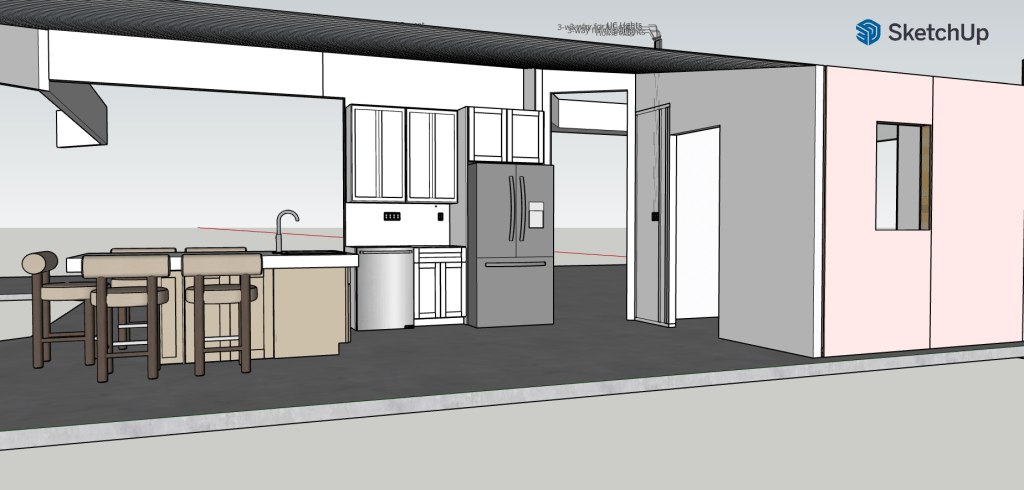
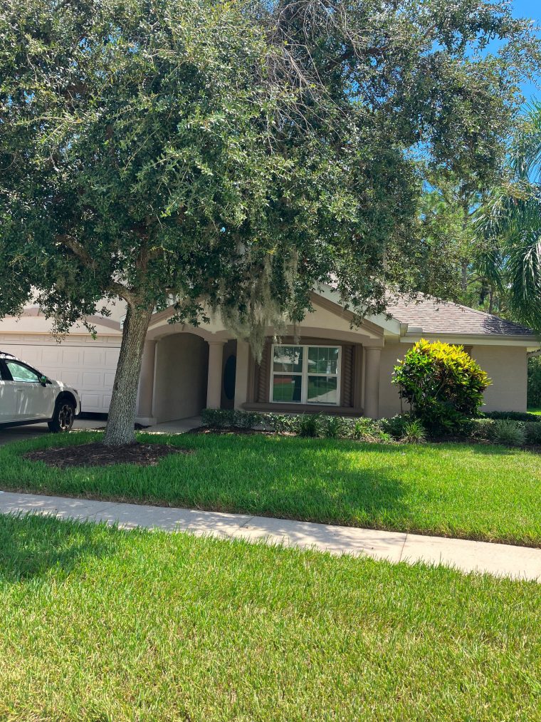
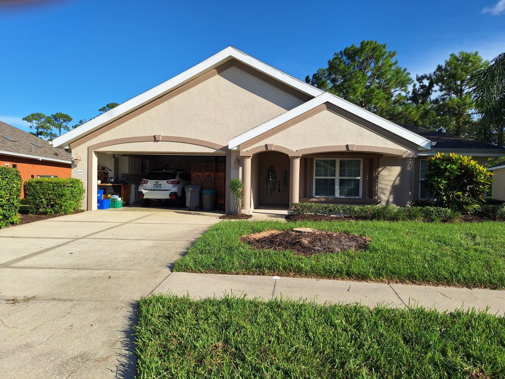
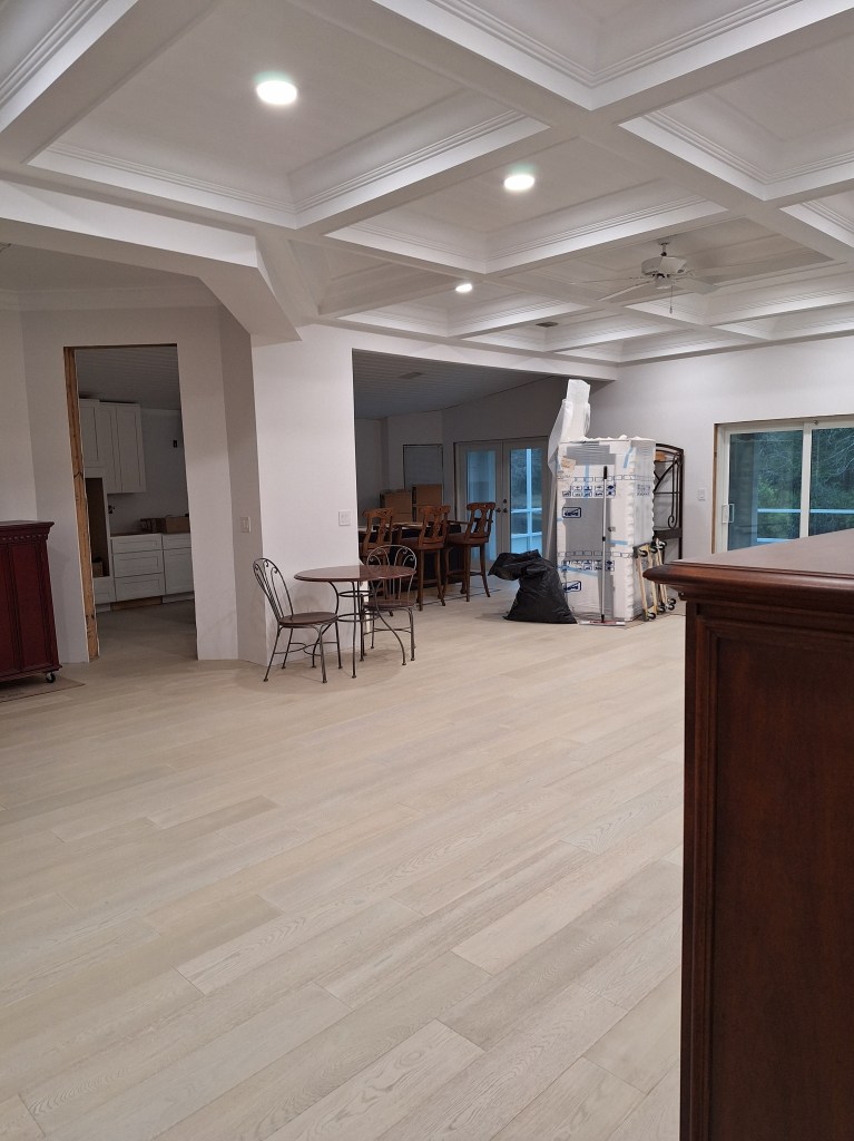
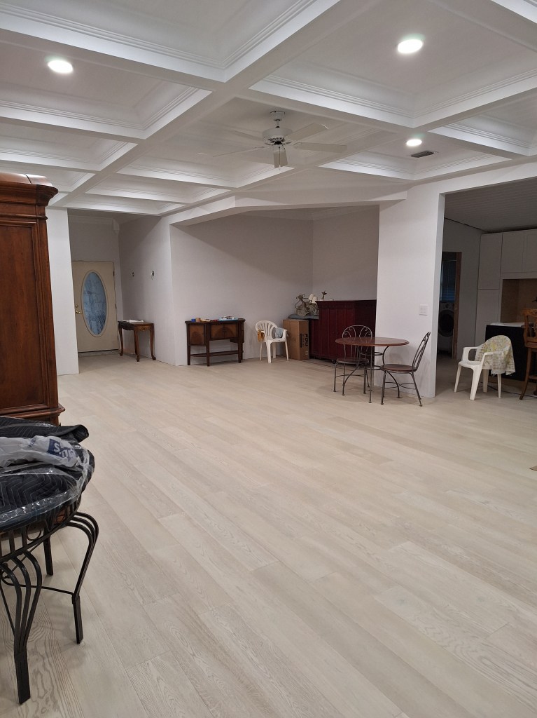
Guest Bedroom, Laundry Room, and Master Closets – March/April 2024

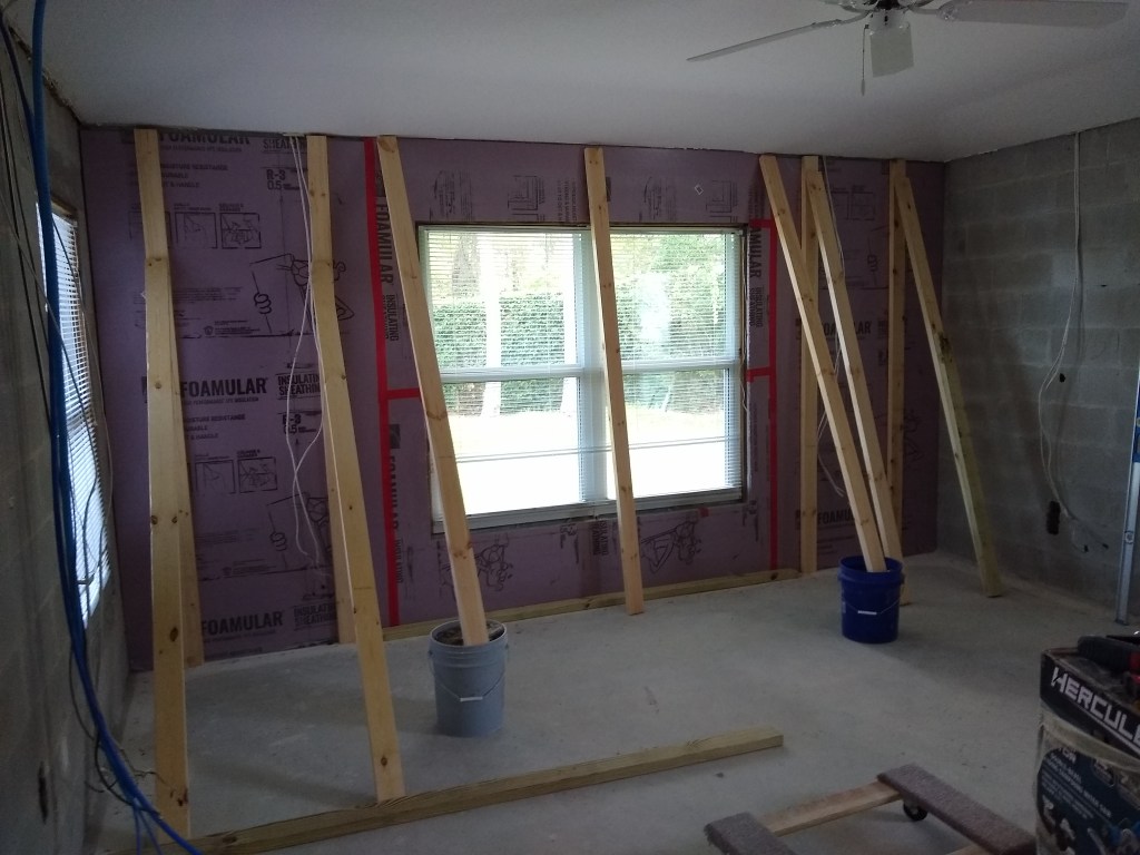
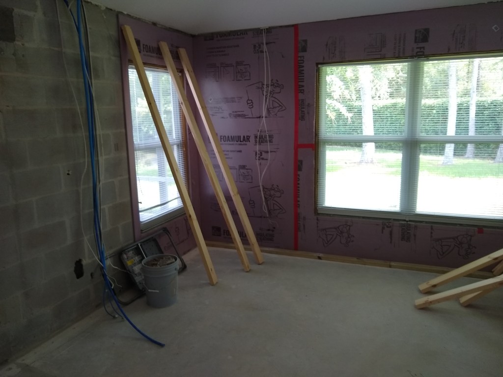
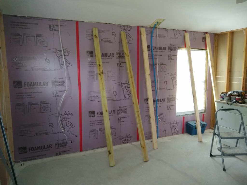
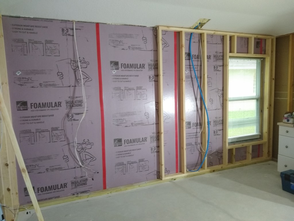
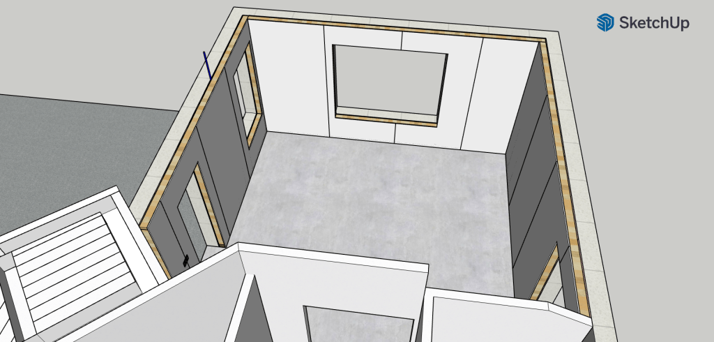
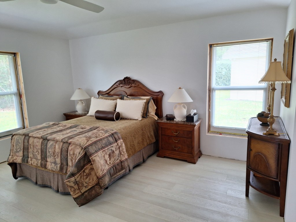
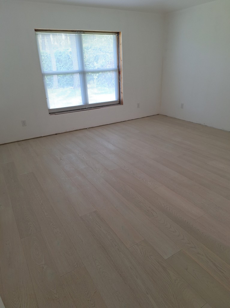
The guest bedroom was the first room where I did any drywall work. I started there because I figured it would be the least used room, and if I was going to make any mistakes, I’d rather it not be something I saw every day. Fortunately it went very well and I was happy with the results. I did that work in July/August of 2021. I stopped working on it after finishing the ceiling (primed and painted) and after priming the walls. I didn’t know what color I was going to paint the walls, so I moved on to other things.

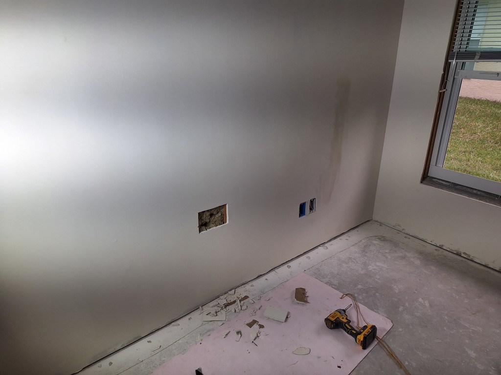
It was not long after I finished working on the guest bedroom that I decided to sell the house I was living in, which was about an hour south of this one, and move into an apartment next to my community, saving me a considerable commute. Since I could not fit everything from my house into my small apartment, I stored most of it in the various bedrooms of the house under renovation. The guest bedroom, being the only bedroom with the drywall finished, received the bulk of the contents I had to store. Now that I was ready to paint it, I had a lot of stuff to shift. I moved almost all of it into the now empty office and used this as an opportunity to organize it in a way that it was easier to get at. The things I had previously stored in the guest bedroom had been put there by the movers, so whenever I had a need for something I knew was stored away, it was often an adventure locating it and often involved climbing over boxes and furniture. With that done, I was ready to start.

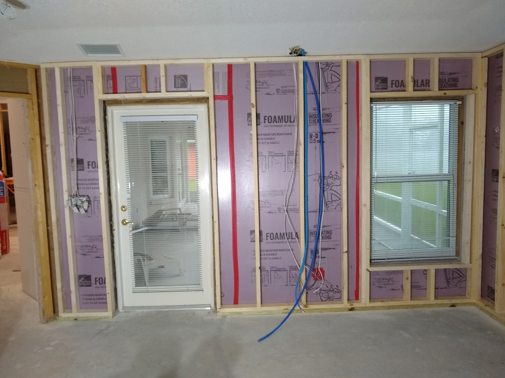
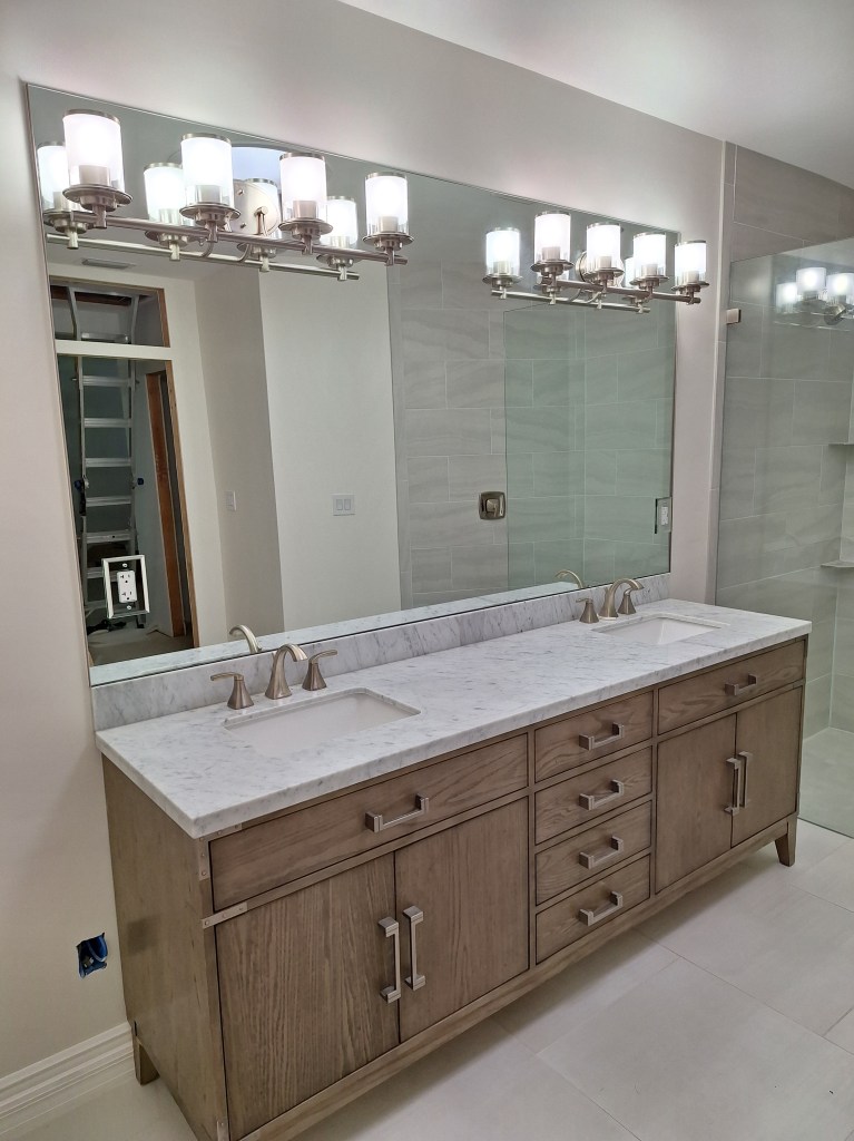
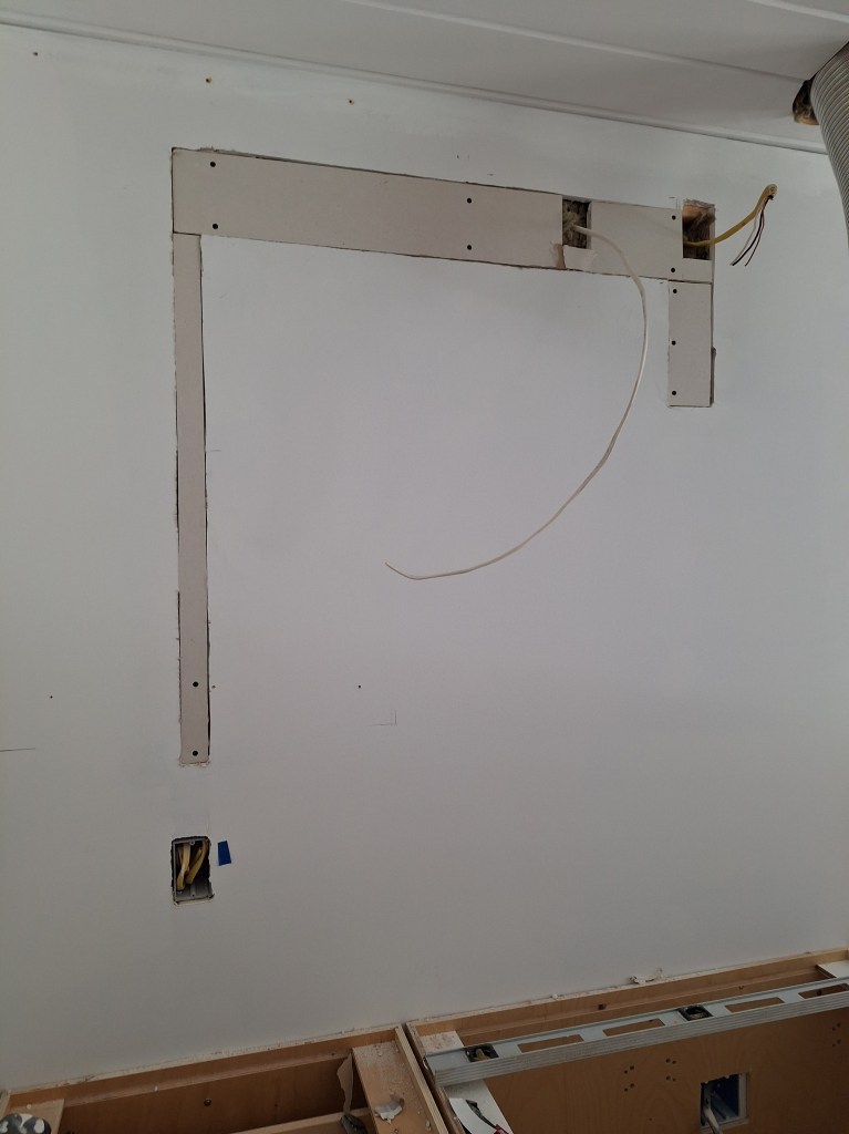
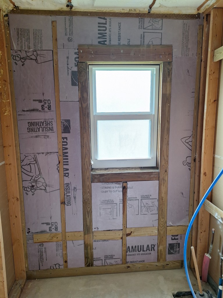
Before any painting could take place, I had to address a problem that arose while working on the master bathroom. The master bathroom shares a wall with the guest bedroom. During the demolition of the ceiling in the master bathroom, a small part of the drywall in the guest bedroom was damaged. So I cut out the damaged portion and fit a patch.

Wall Patch – Opening Cut.
Wall Patch – Opening Closeup.

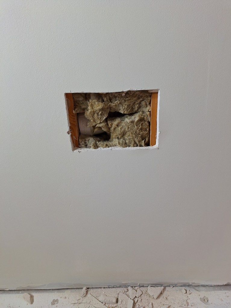
I cut the opening enough so that I had something to screw the patch piece into on either side. In addition to screws, I also used construction adhesive, as I usually do.

Wall Patch – Patch Installed.

The patch piece could have been a bit tighter, but since I was going to prefill it, I would have to open the seems a bit anyway, so I decided this was sufficient. Here is the prefill.

Wall Patch – Prefilled.

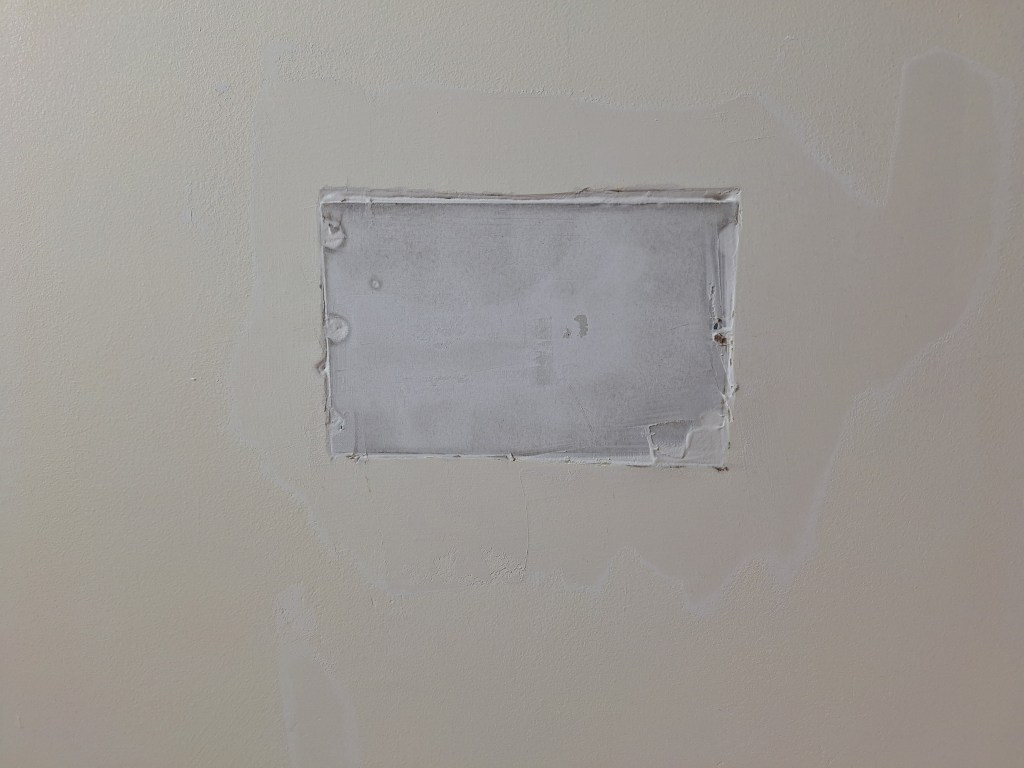
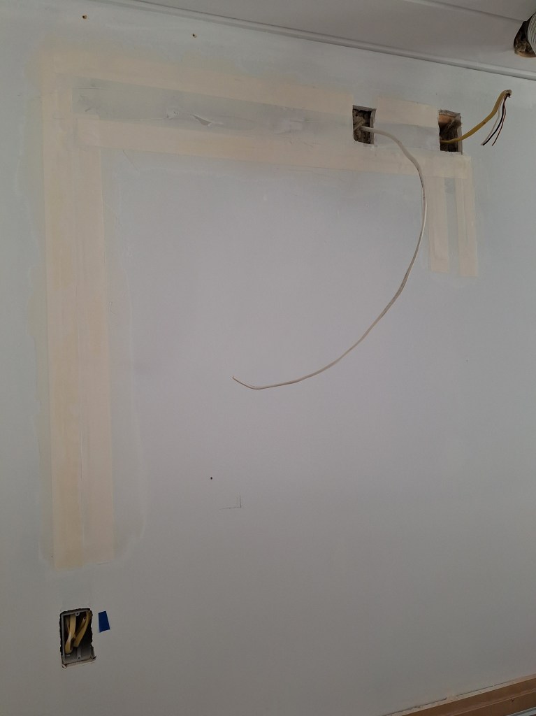
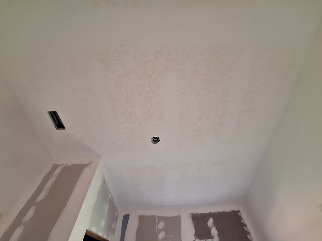
When taping, I decided to try something a bit different from my usual. Instead of running tape along all four seems, I simply ran three horizontal strips. By doing this I don’t have any overlapping tape to smooth out when I cover the tape with mud. I think this will be fine.

Wall Patch – Taped.

After coating a couple of times, followed by a final tight skim coat, it was ready for painting.

Wall Patch – Ready for Paint.

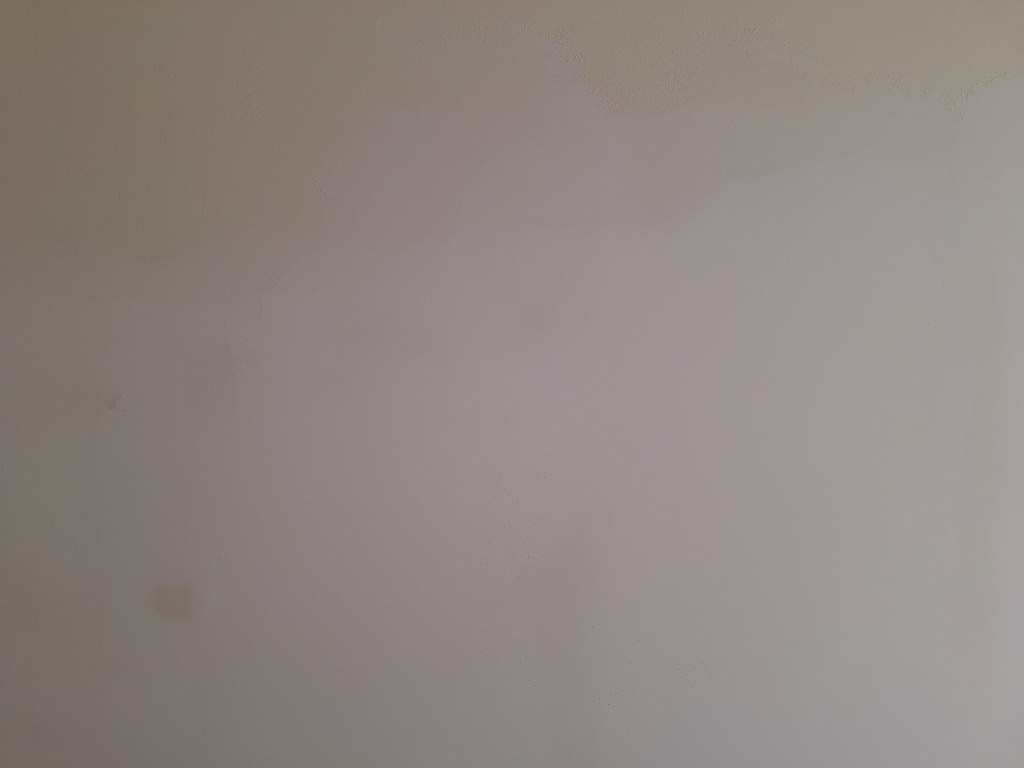
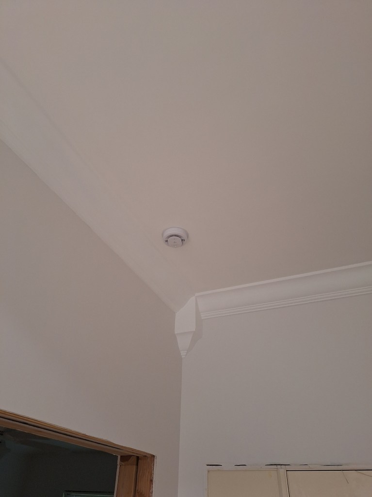
Not much to see in the image above other than there being no evidence of the patch.

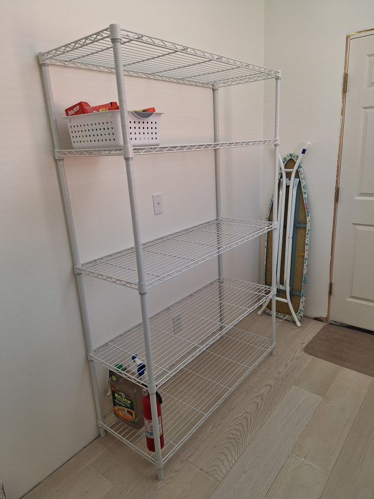
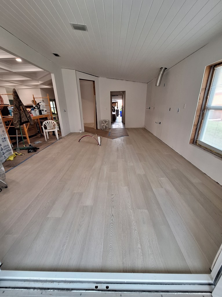
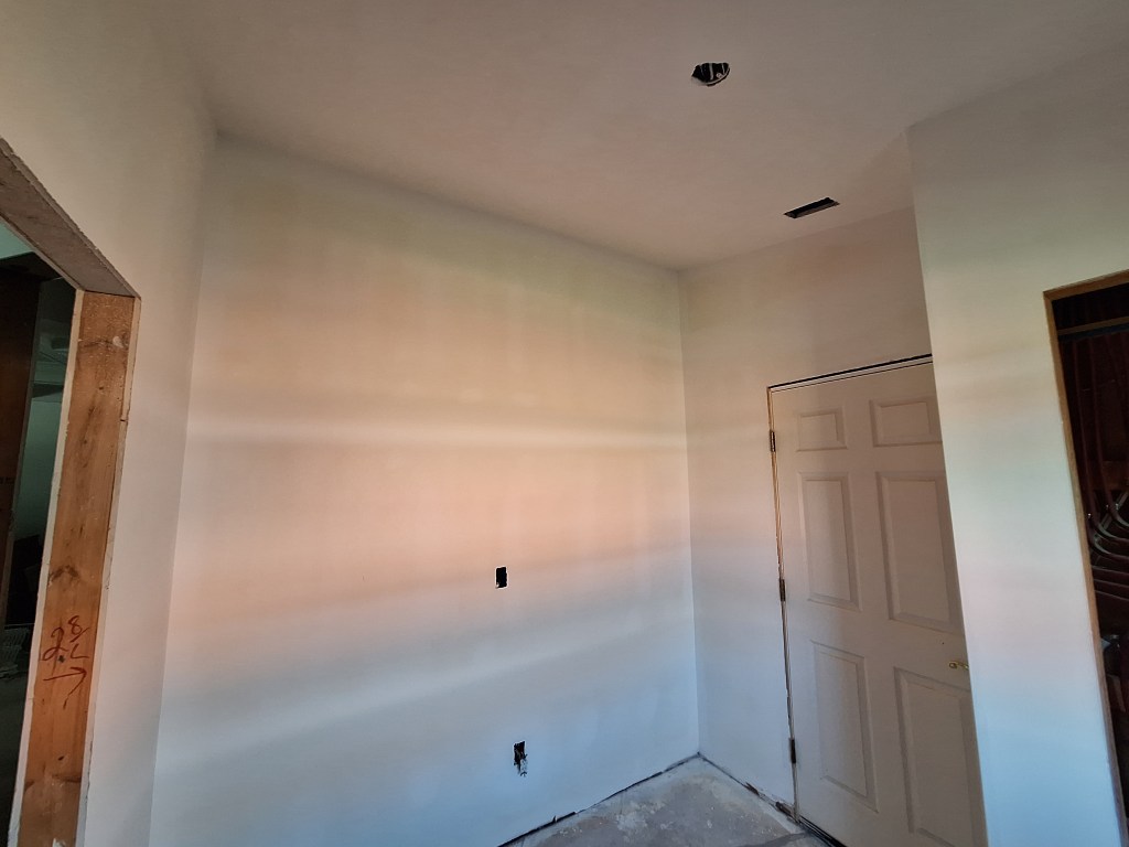
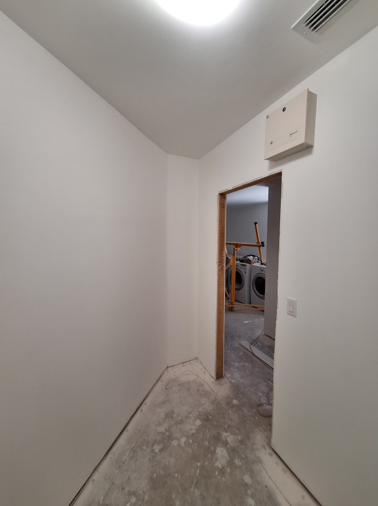
Since preparing the patch for painting required several days due to the drying time between coats, I started painting the other walls. I used the same paint I used in the office; namely Behr Dynasty Beach House. When that was done I was able to start painting the wall with the patch. After getting the first coat done, which didn’t take long, rather than wait until the next day to start the second coat, I started on some of the other tasks I knew were ahead of me. Most notably was getting a head start on the laundry room, which was where I was going after being done (for now) with the guest bedroom. Like the rooms before the guest bedroom, the laundry room required that I clear it out so that I could get at all the surfaces. So that was the first order of business.

Laundry Room Cleared – From Entrance to Kitchen.
Laundry Room Cleared – Toward Entrance to Kitchen.

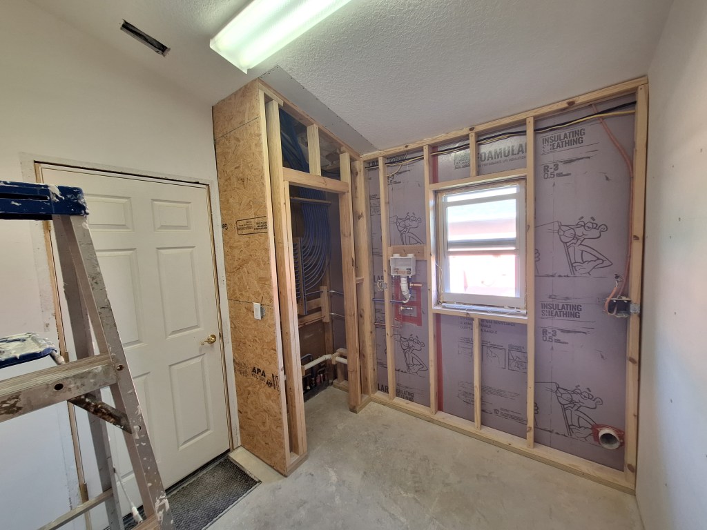
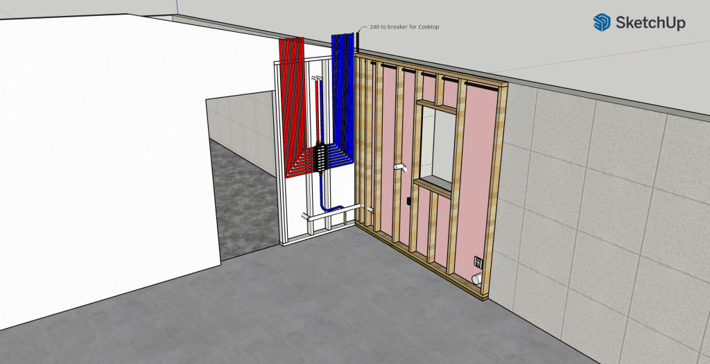
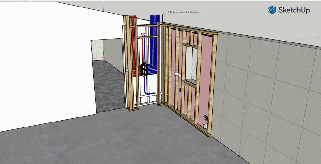
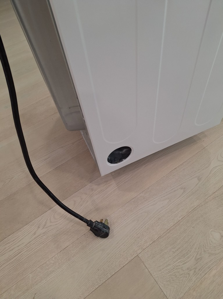
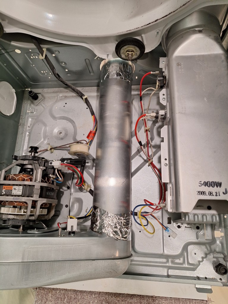
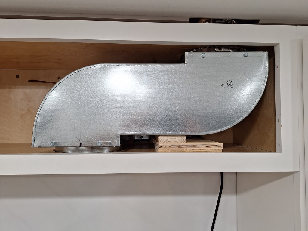
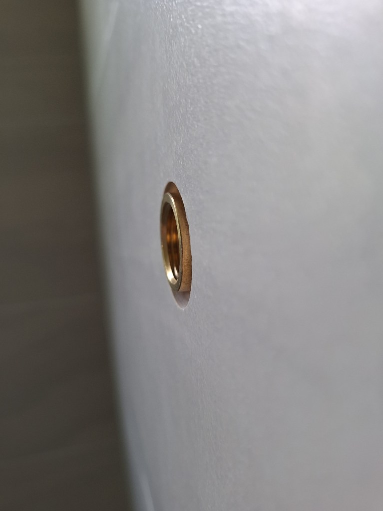
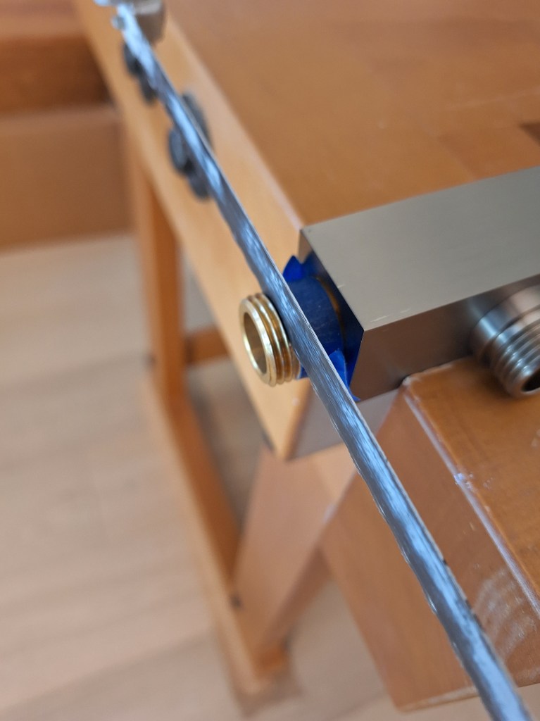
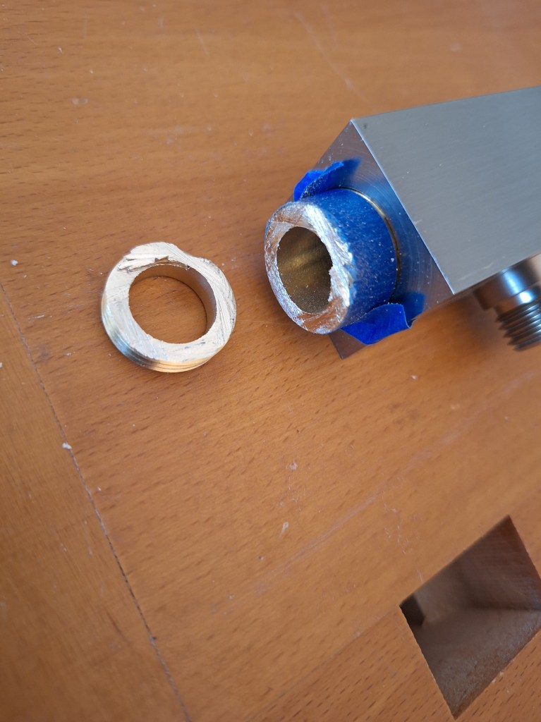
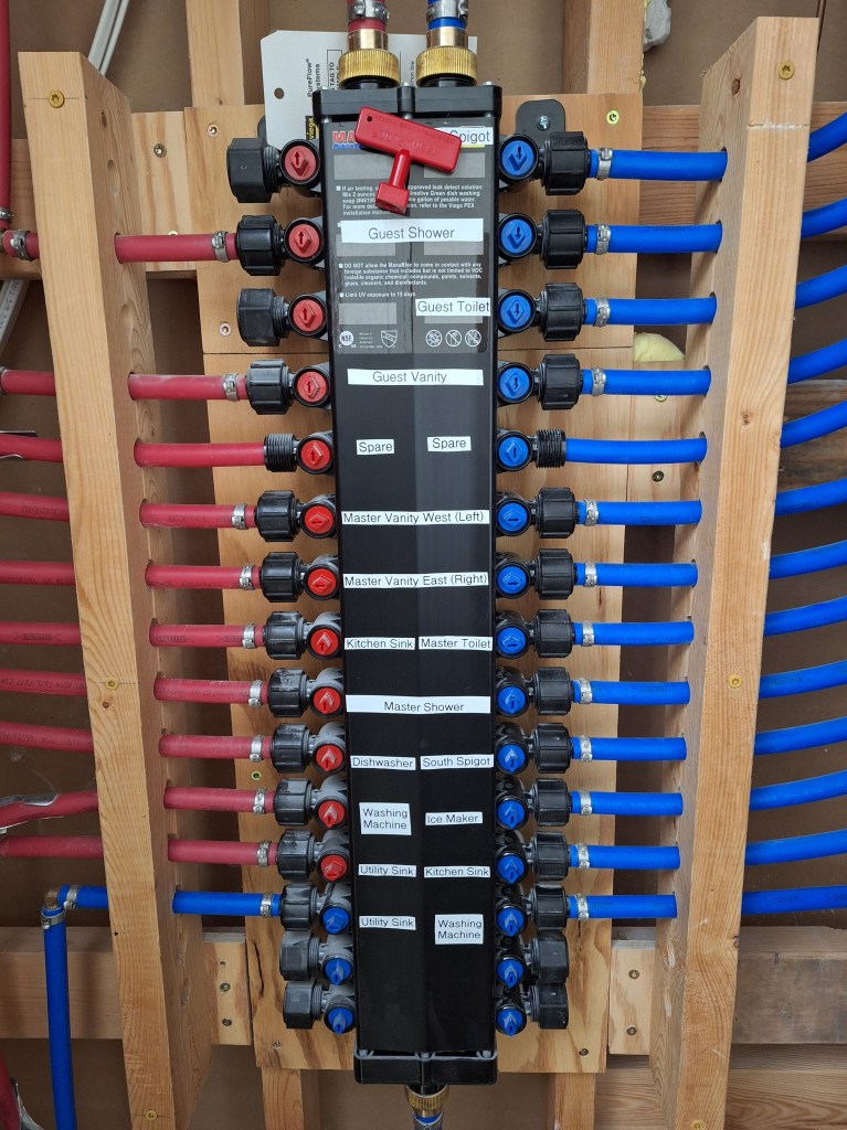
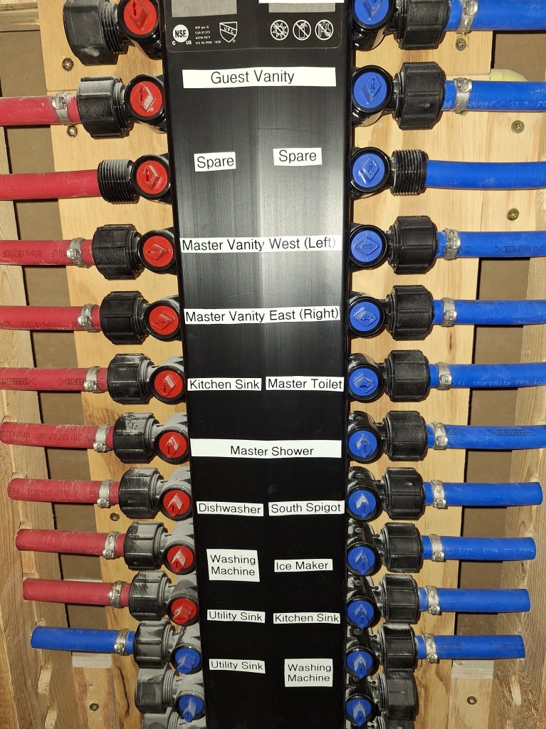
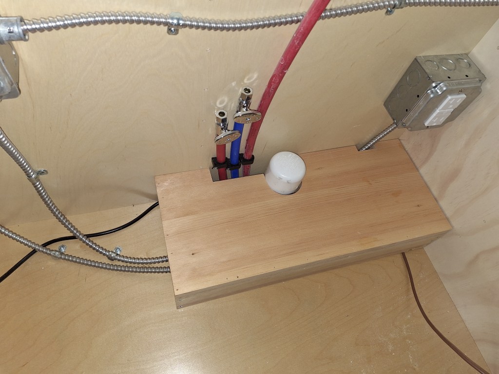
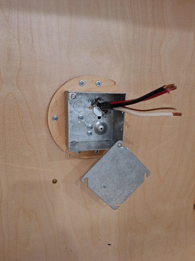
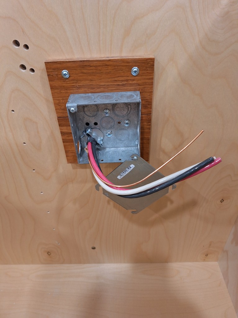
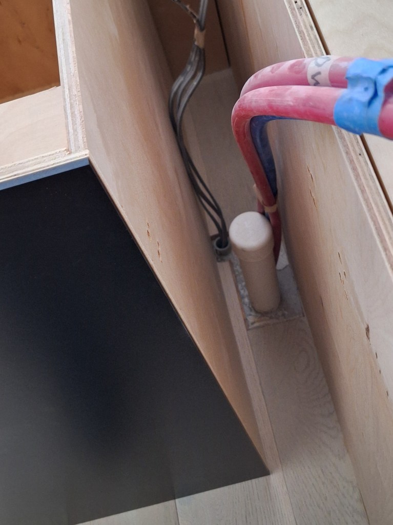
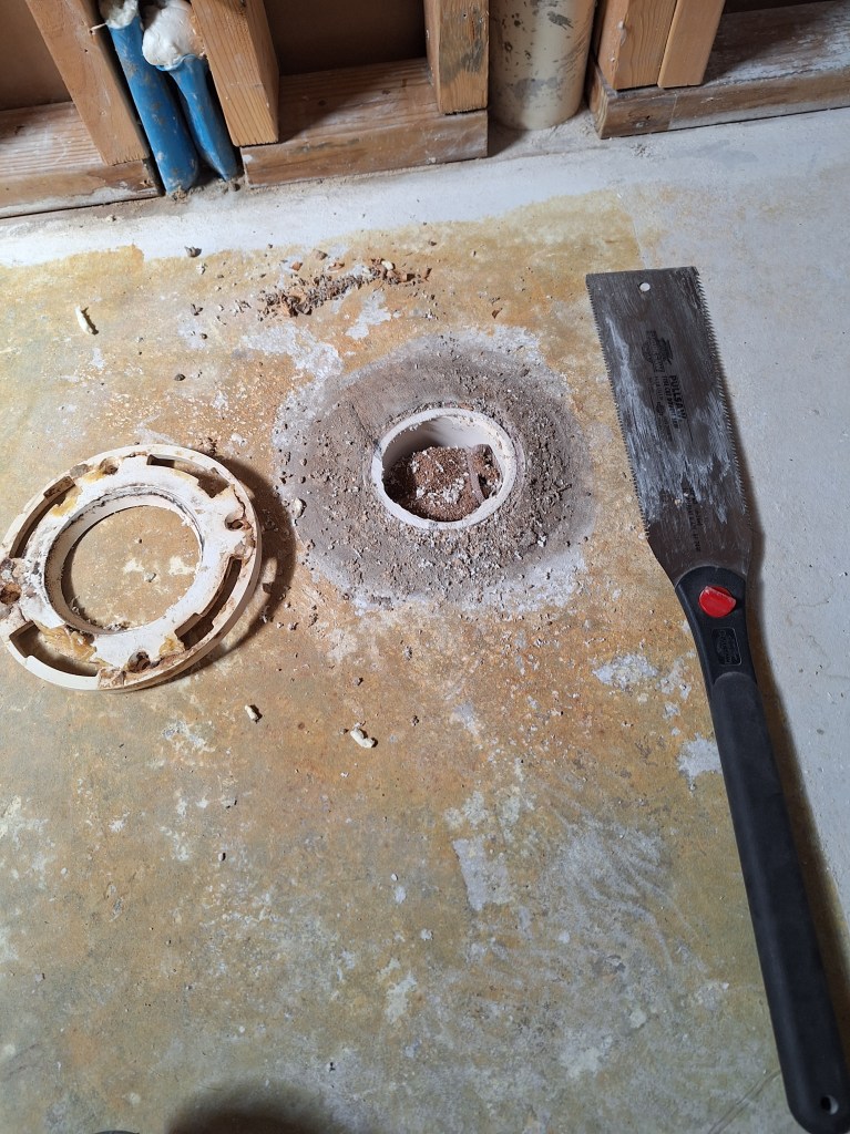
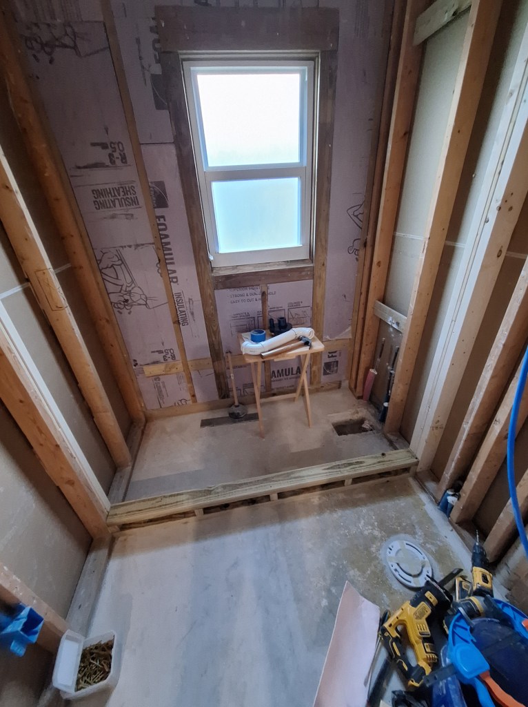
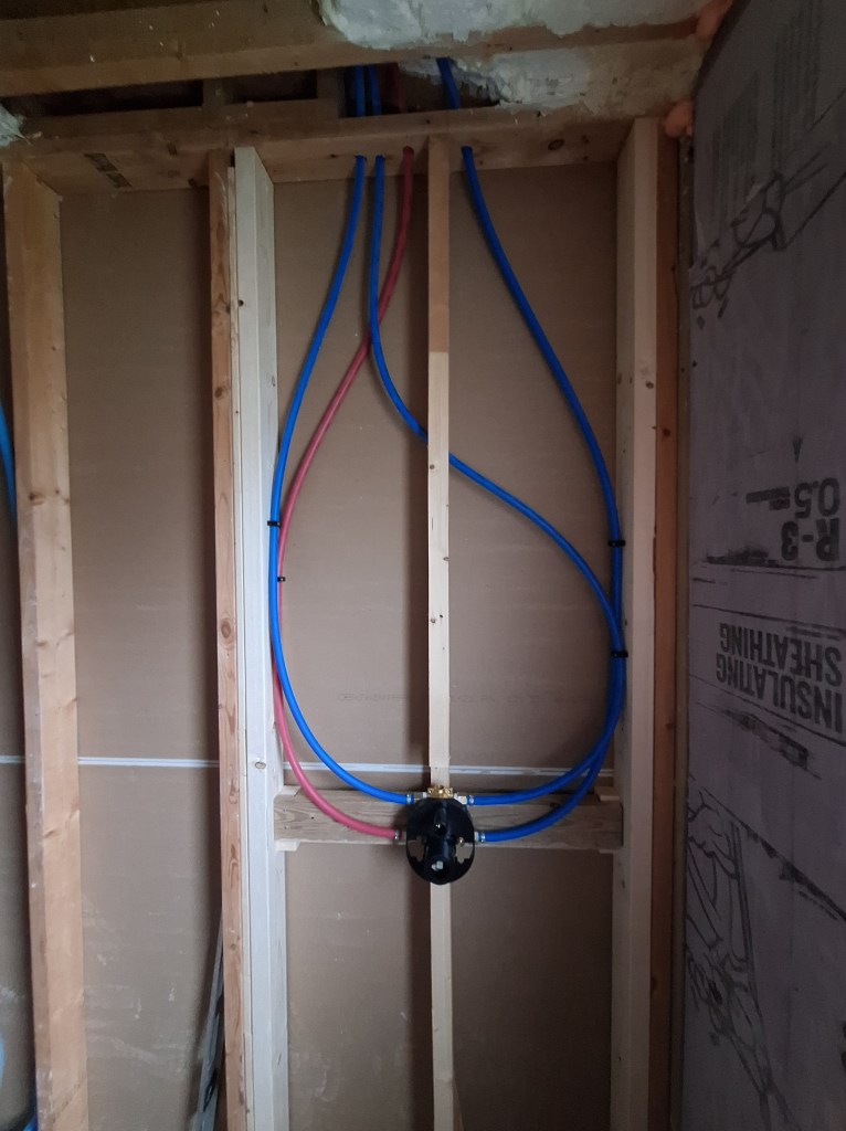
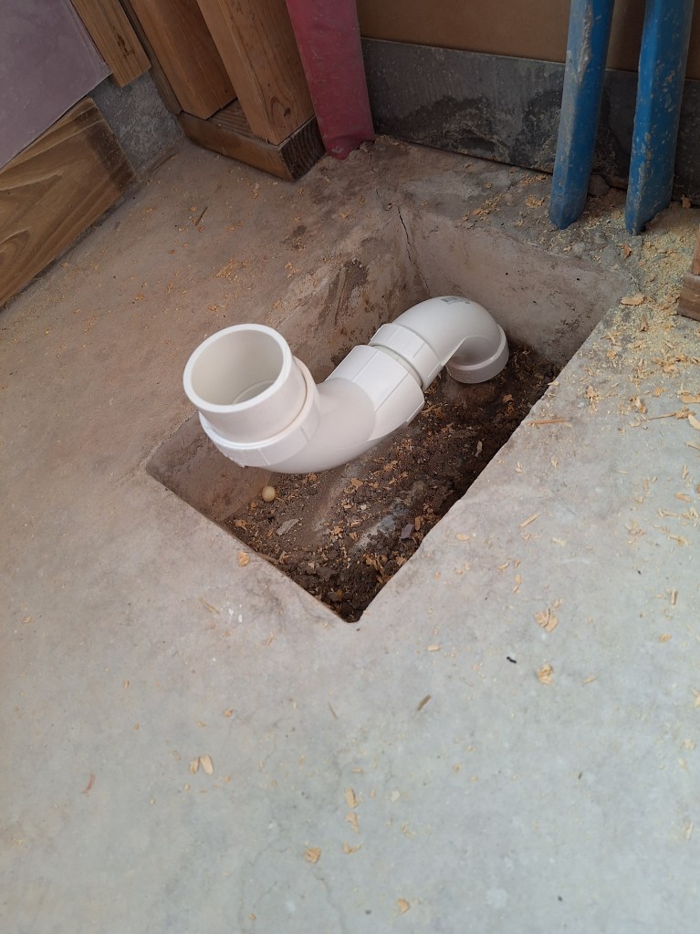
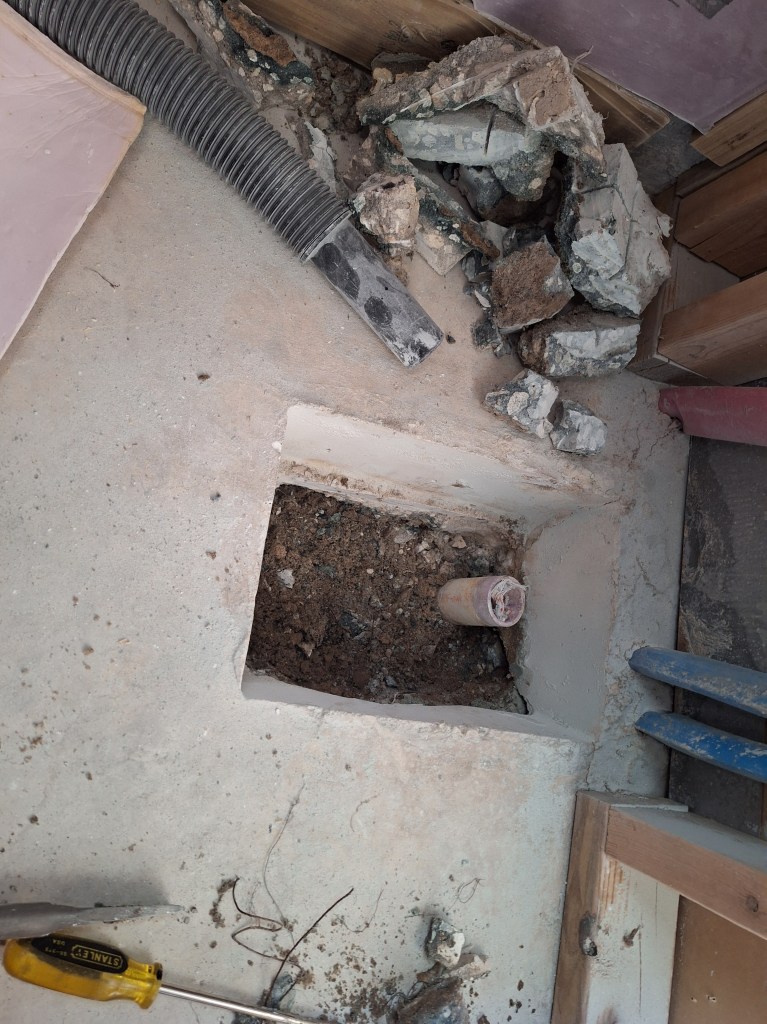
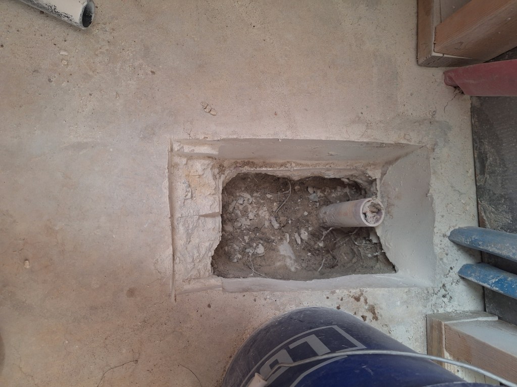
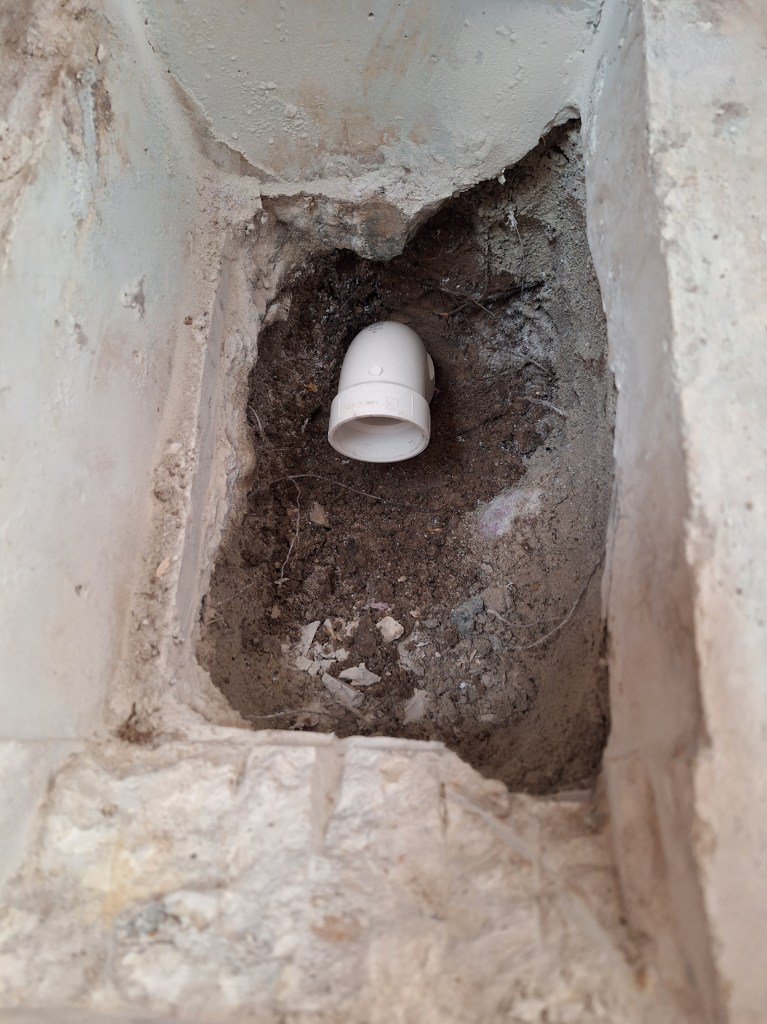
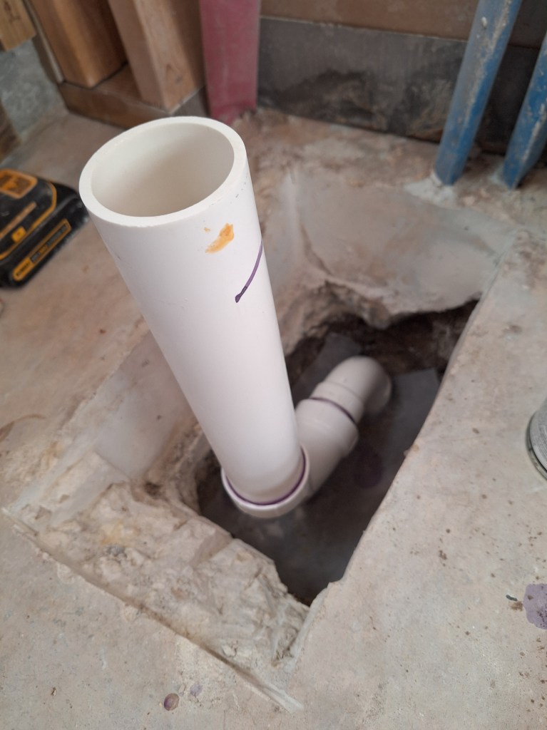
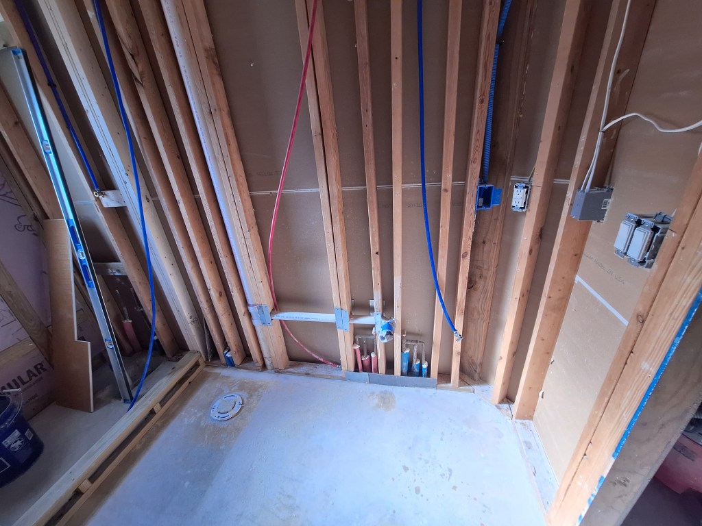
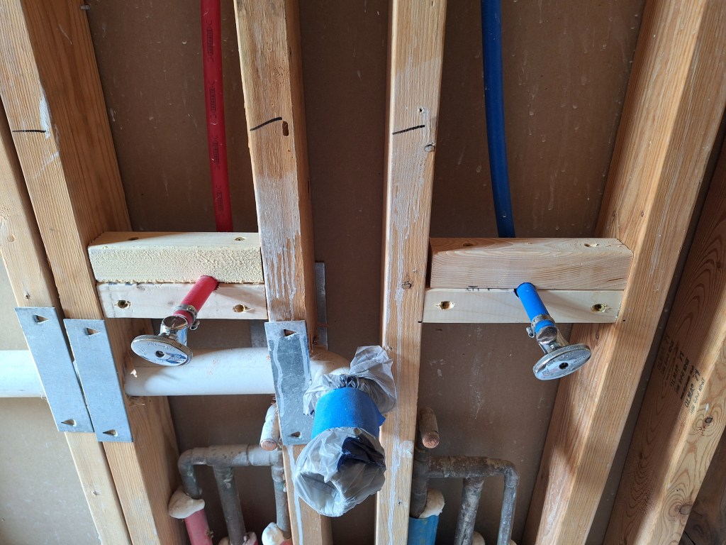
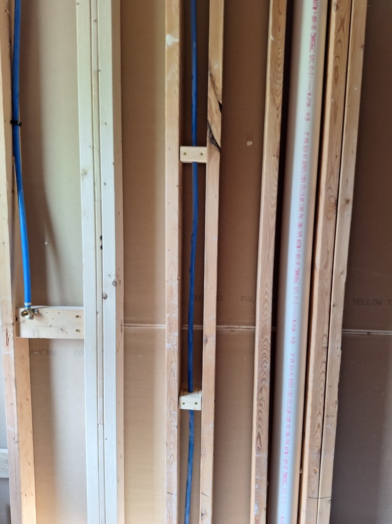
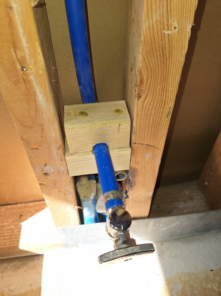
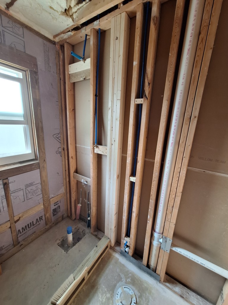
If you look at the first of the images above, you’ll also notice that I removed the trim from around the door to the garage, and I also installed a piece of drywall to close the opening between the plumbing closet and the existing ceiling. I also installed a couple of water hammer arrestors for the supply lines to the washer (shown more clearly below).

Laundry Room – Water Hammer Arrestors Installed.

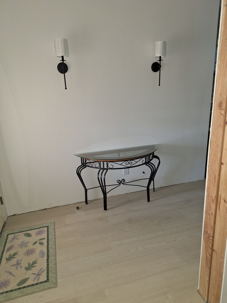
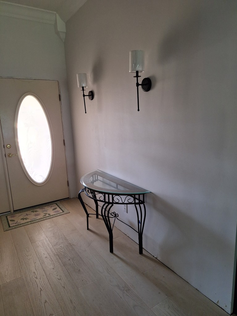
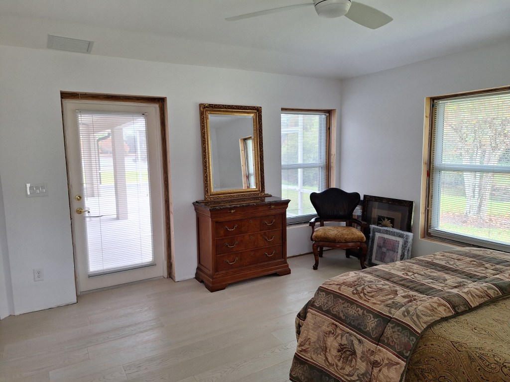
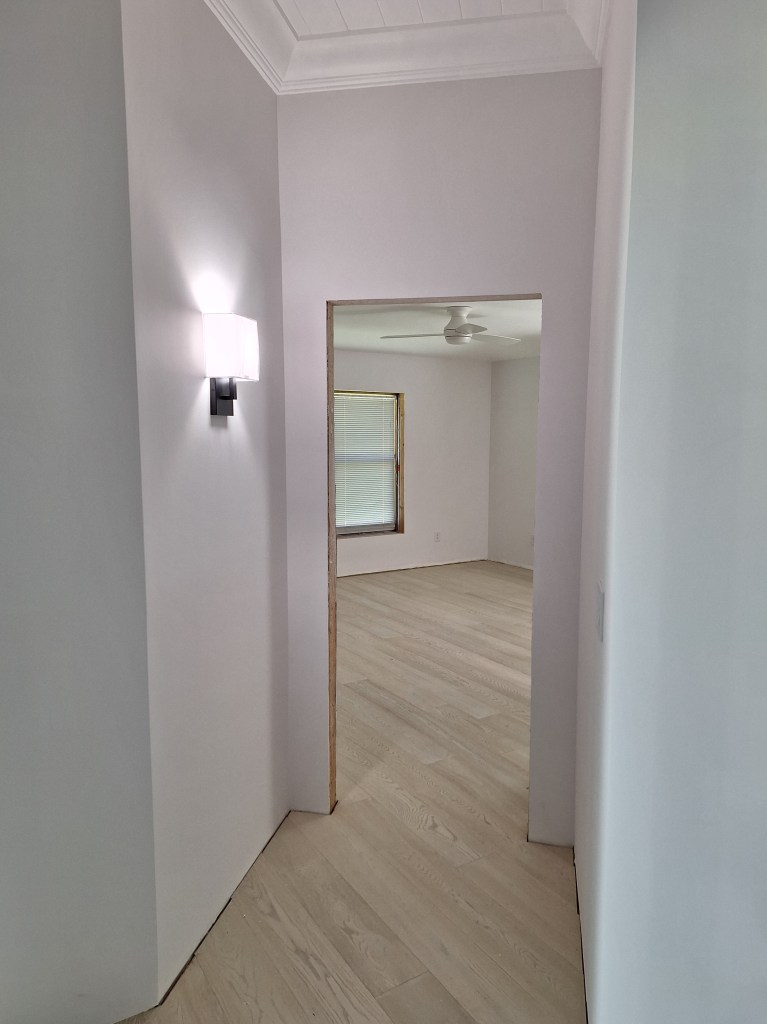
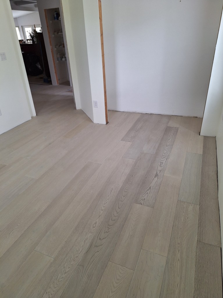
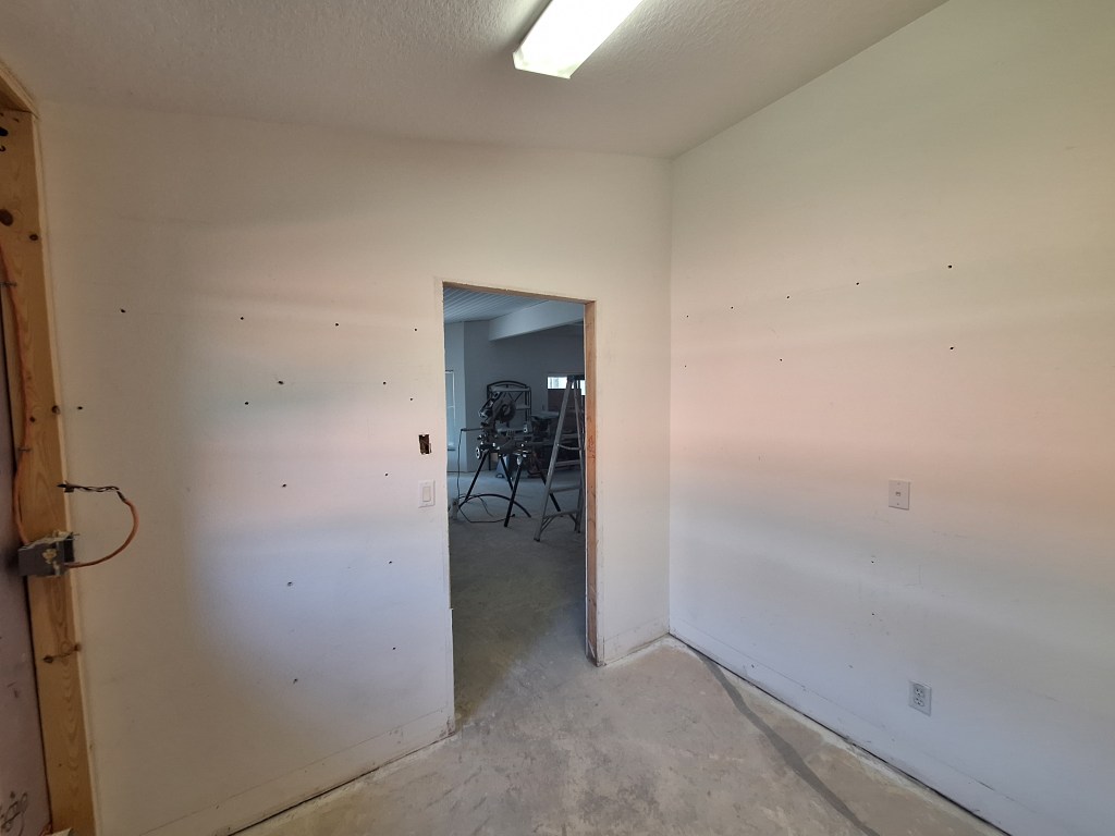
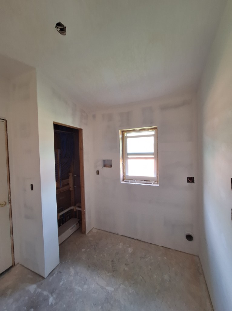
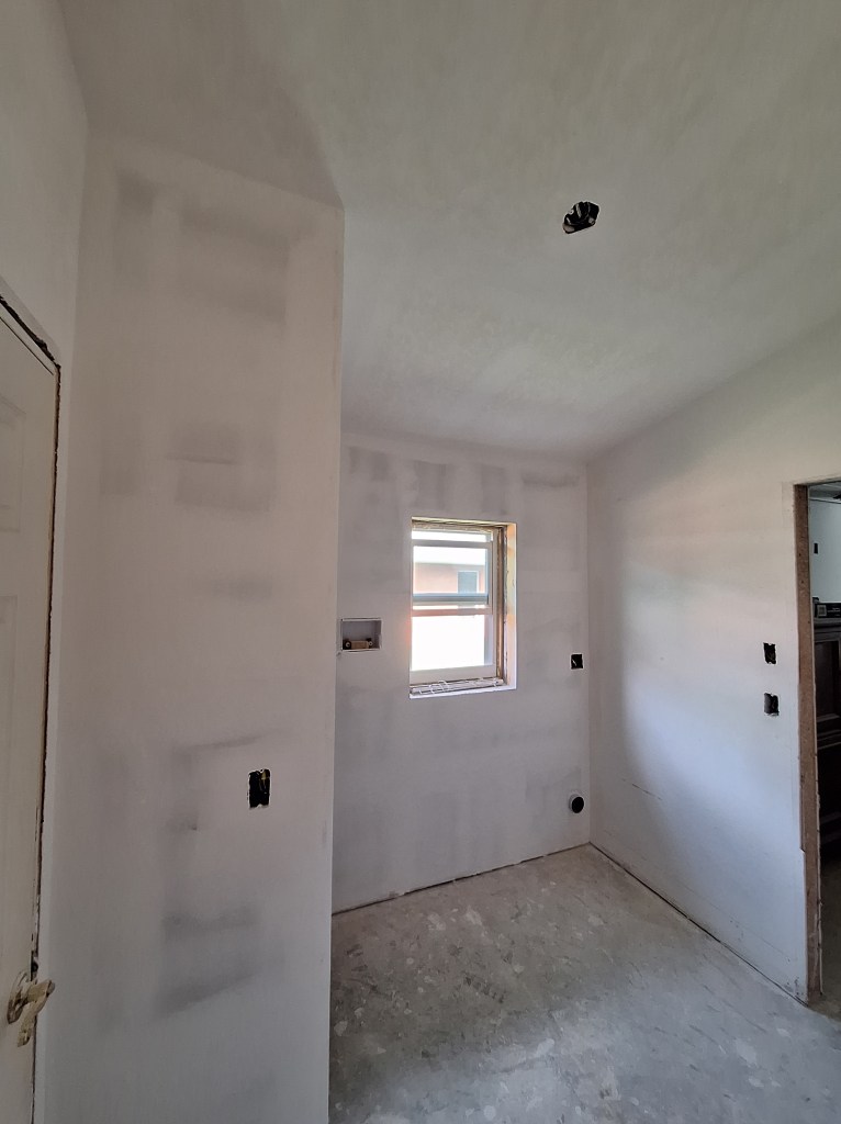
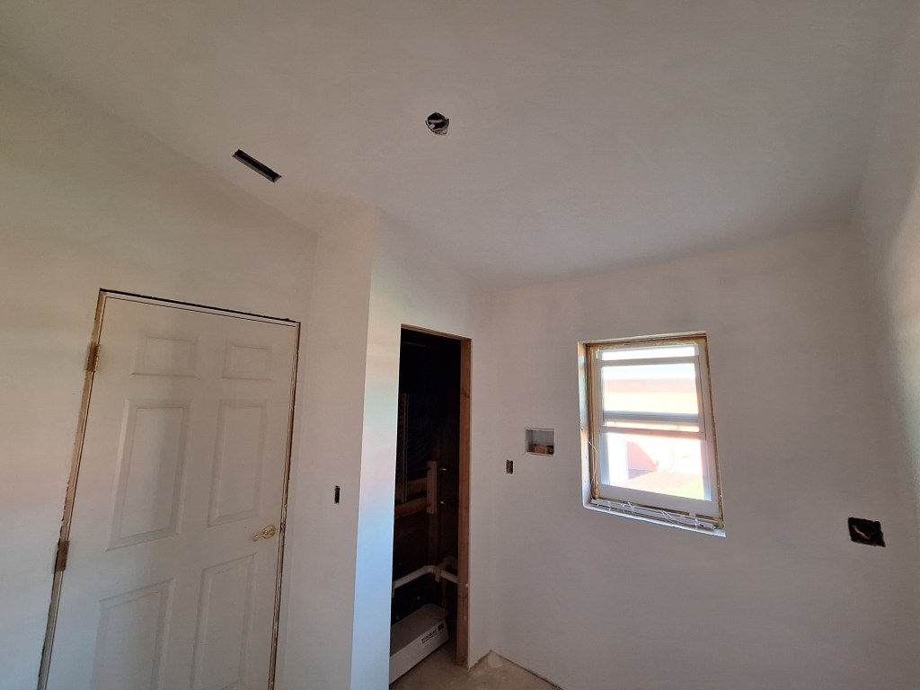
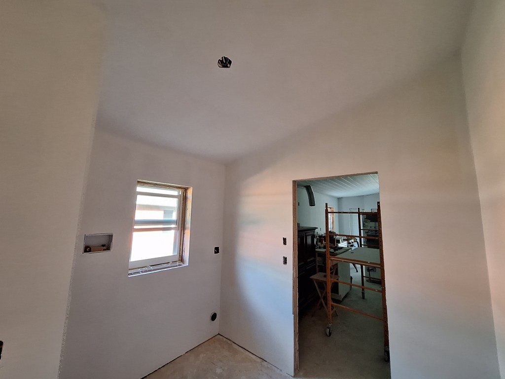
The next time I returned to the house, I was able to paint the second coat on the south wall to finish the painting for the guest bedroom. Here it is finished.

Guest Bedroom Painted – From Entrance.
Guest Bedroom Painted – From Closet.
Guest Bedroom Painted – Toward Entrance.

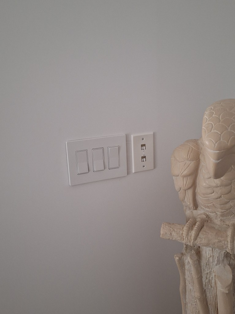
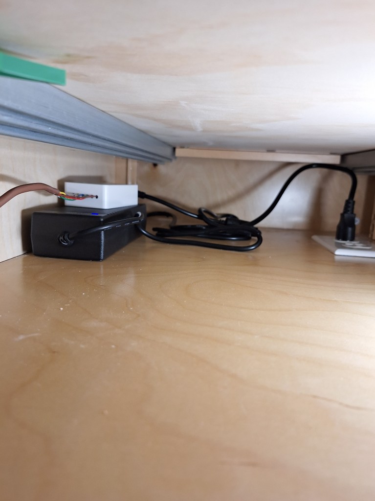
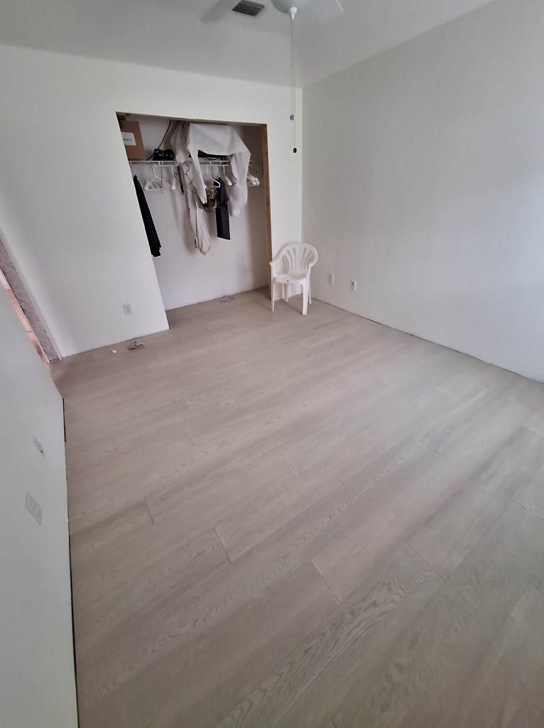
As you can see, I hooked up the outlets and installed the light/fan. This was all I intended to do on the room for now, so I turned my attention back to the laundry room.

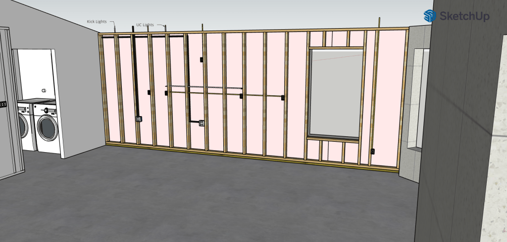
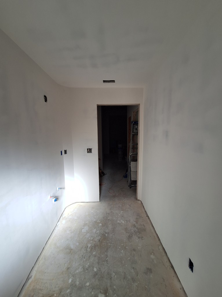
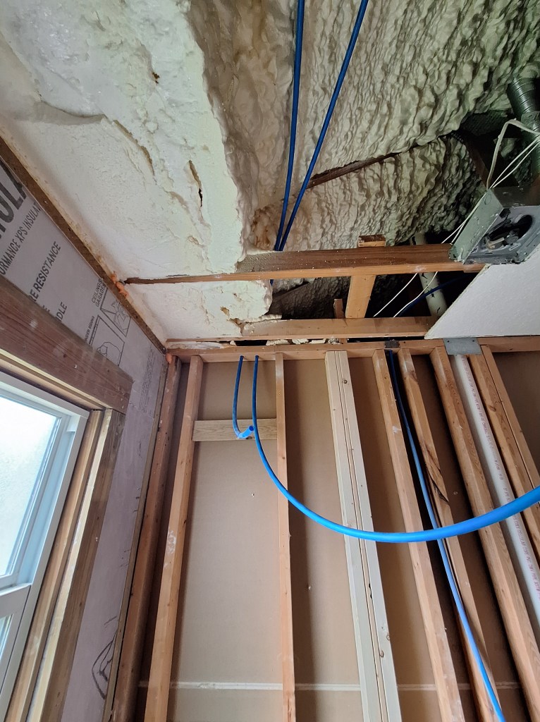
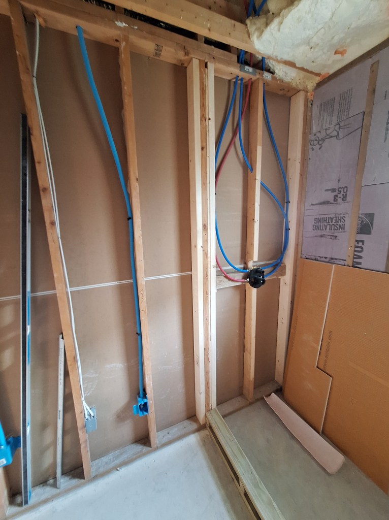
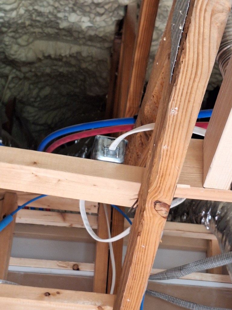
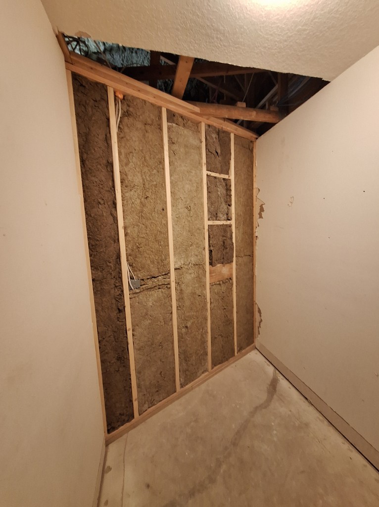
Before hanging drywall in the laundry room, I had to introduce fire block foam into the openings where the electrical wires run into the attic. I ended up adding the foam in more places than that simply because I had plenty of extra, so I got a bit carried away.

Laundry Room – Fire block foam Added.

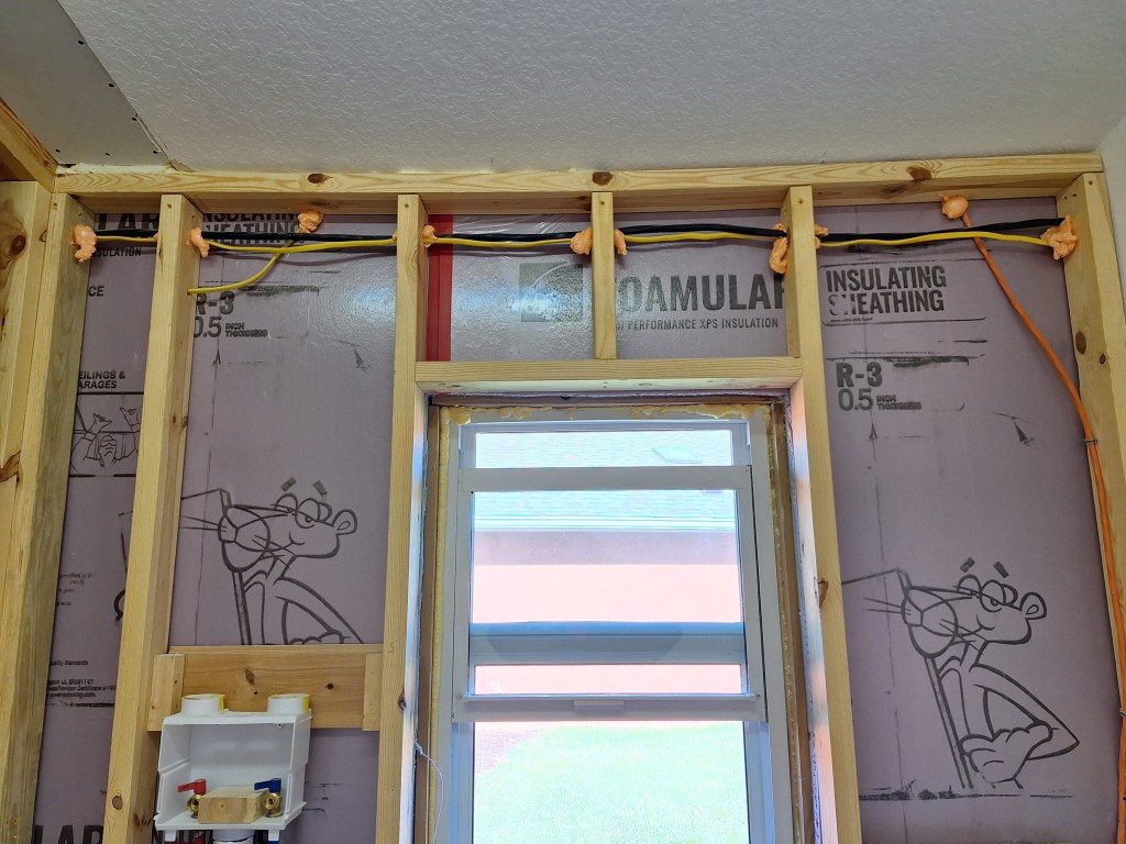
I then added the insulation.

Laundry Room – Insulation Added.

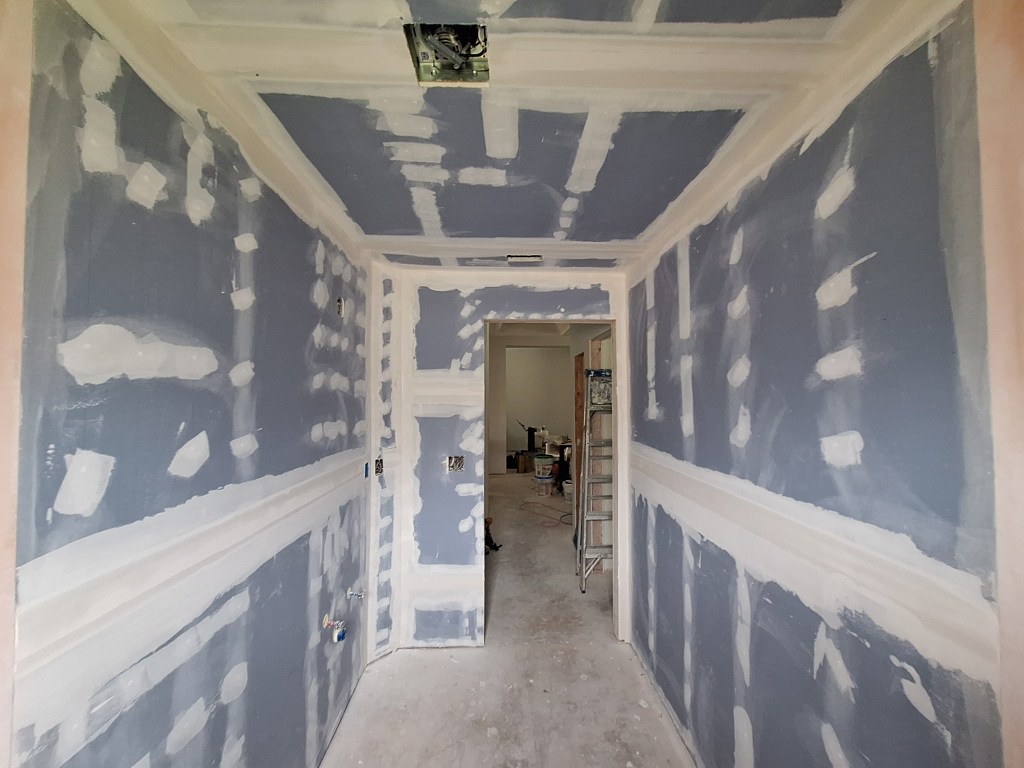
After this I was ready to hang drywall. Since I had a lot of drywall off-cuts, I used them instead of buying new full sheets. Consequently, it was a patchwork.

Laundry Room Drywall Hung – From Kitchen Entrance.
Laundry Room Drywall Hung – From Behind Garage Entrance Door.

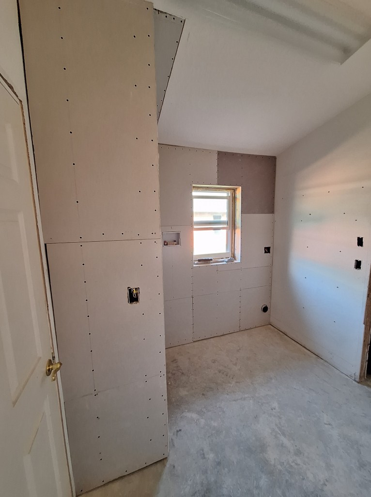
With all these seems, there will be a lot of taping. I prefer that to wasting all those off-cuts. Even with all those taped joints, I’ll make it look great.

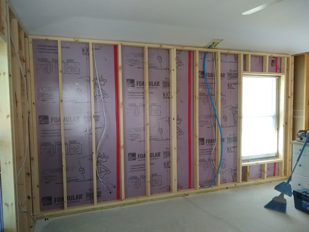
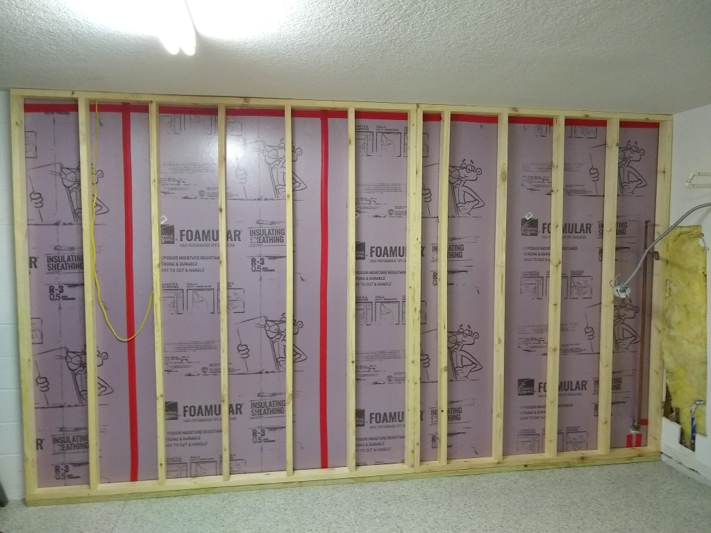
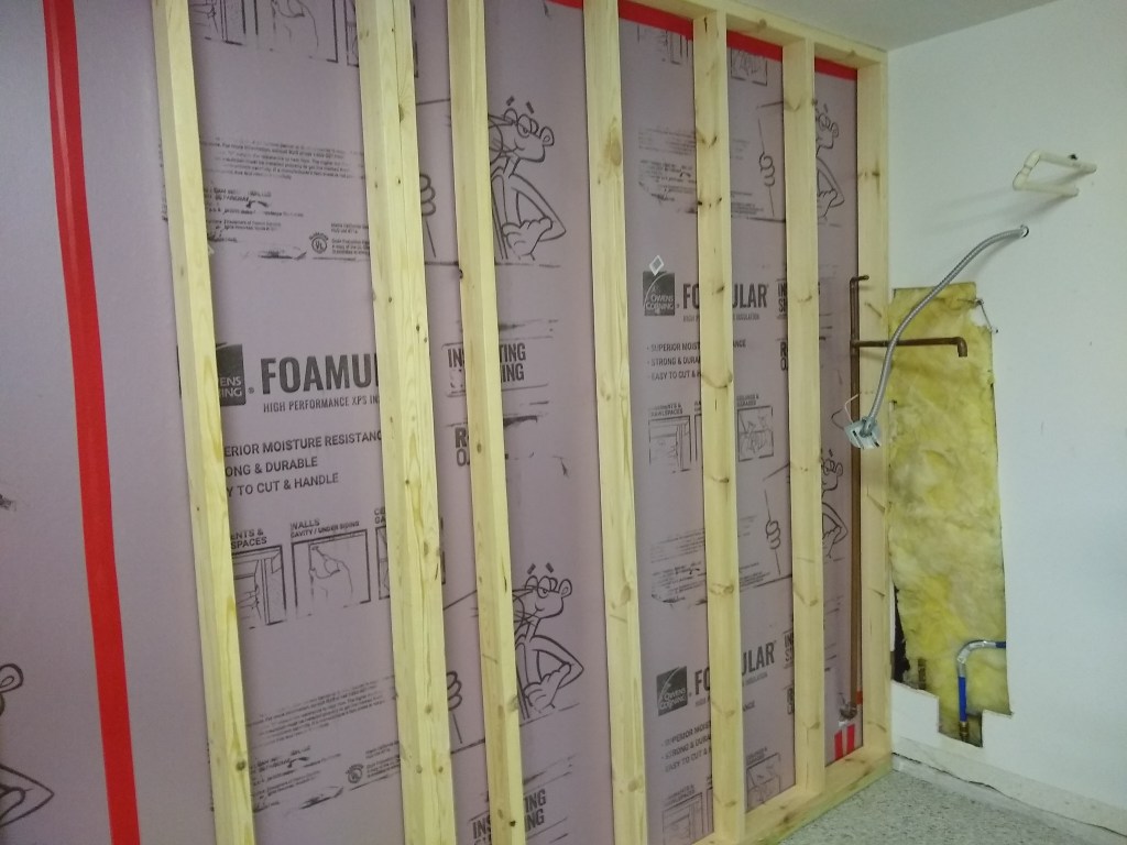
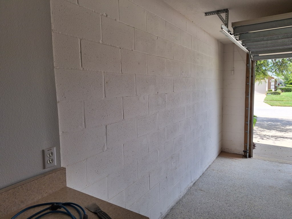
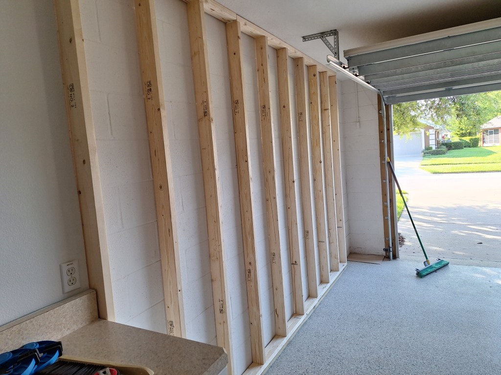
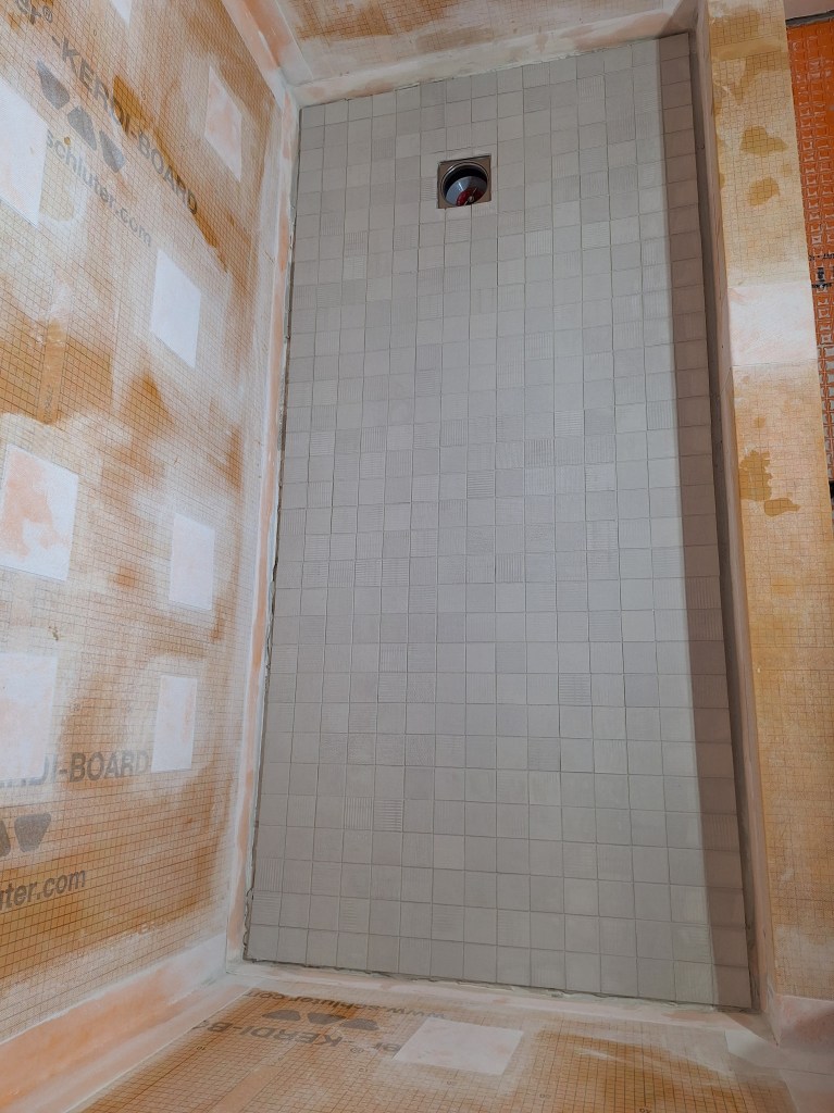
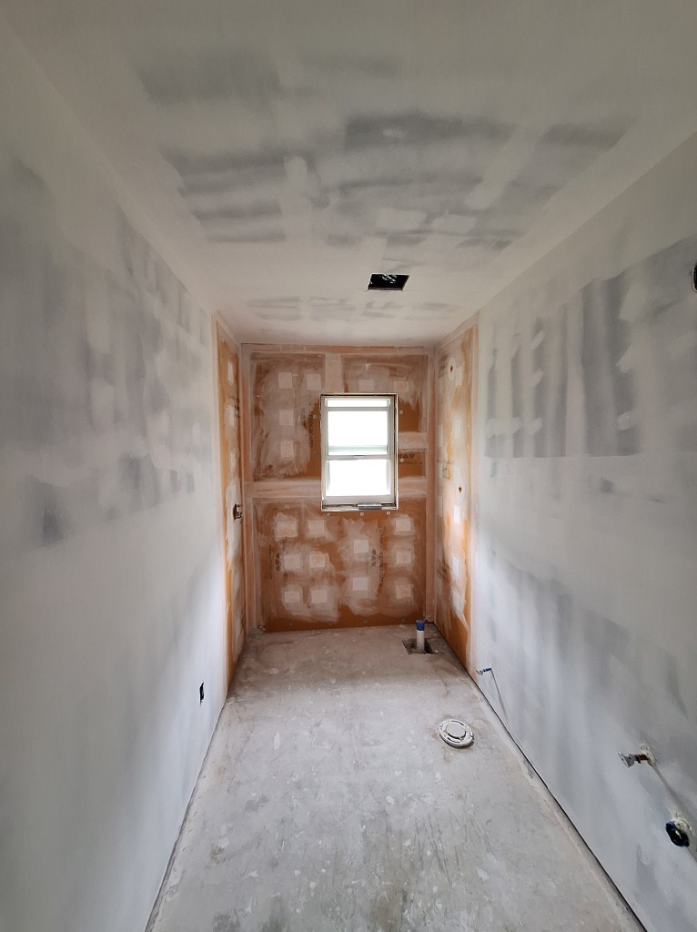
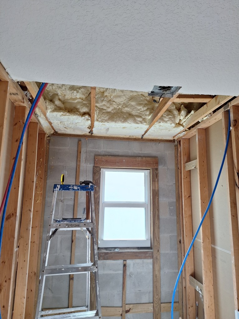
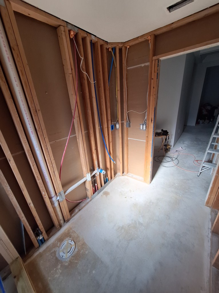
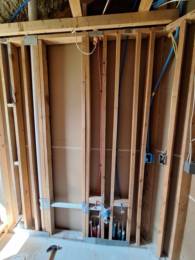
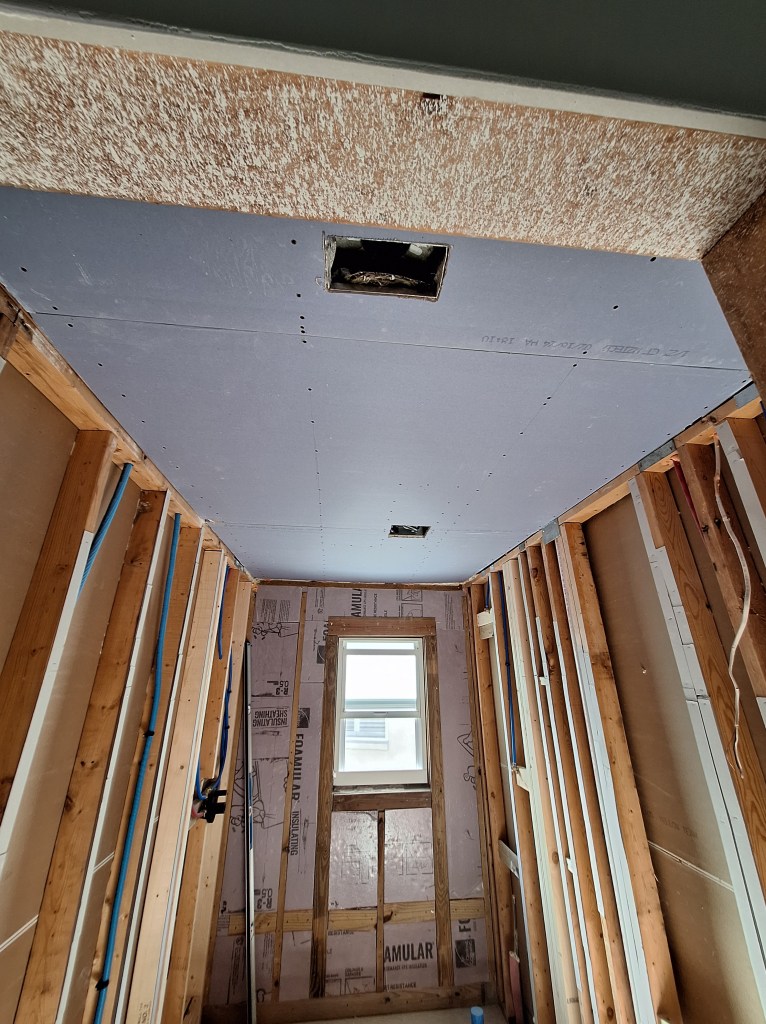
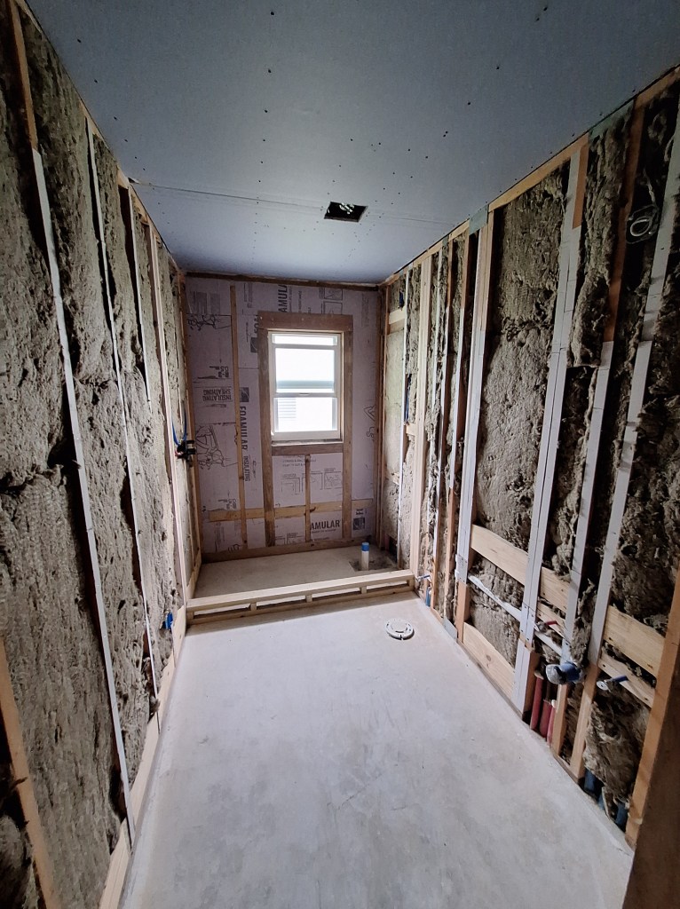
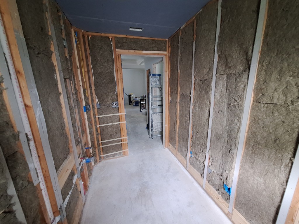
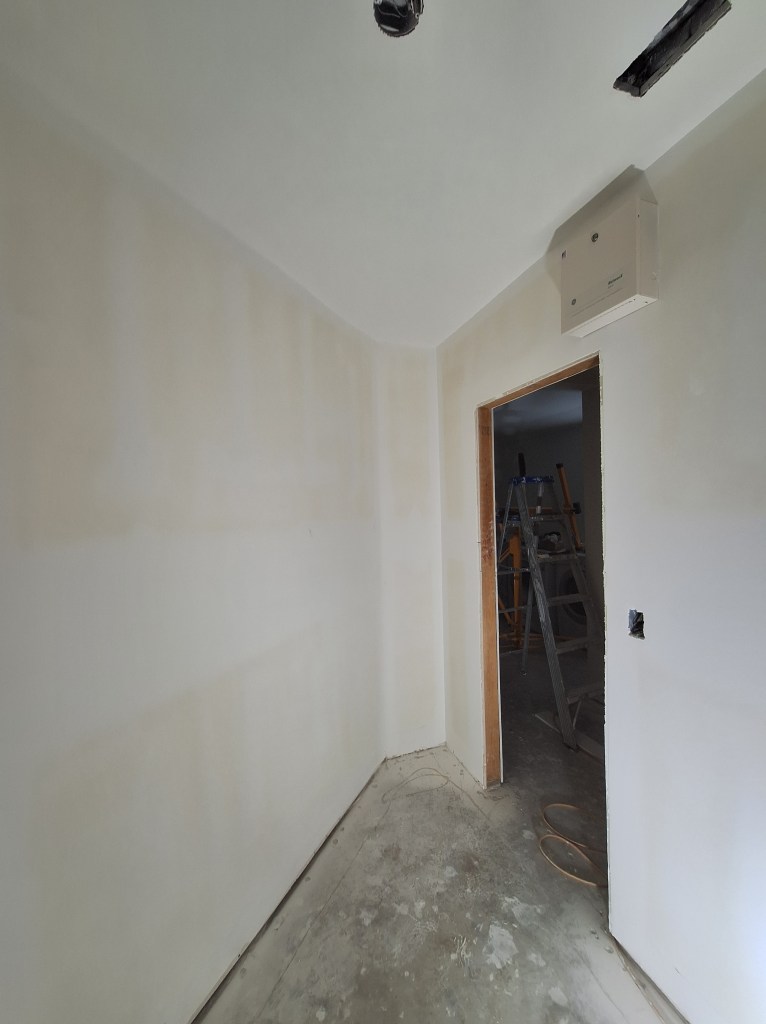
With the drywall hung, I scheduled another inspection. That meant I had to wait a couple of days before I could start taping, so I started working on the large closet in the master bedroom, which was scheduled to start after I was done with the laundry room. The first job there was to add sound insulation between the back wall and the shower.

Large Master Closet – Sound Insulation added.

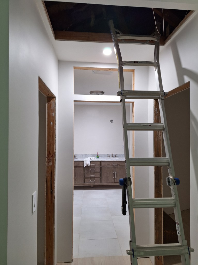
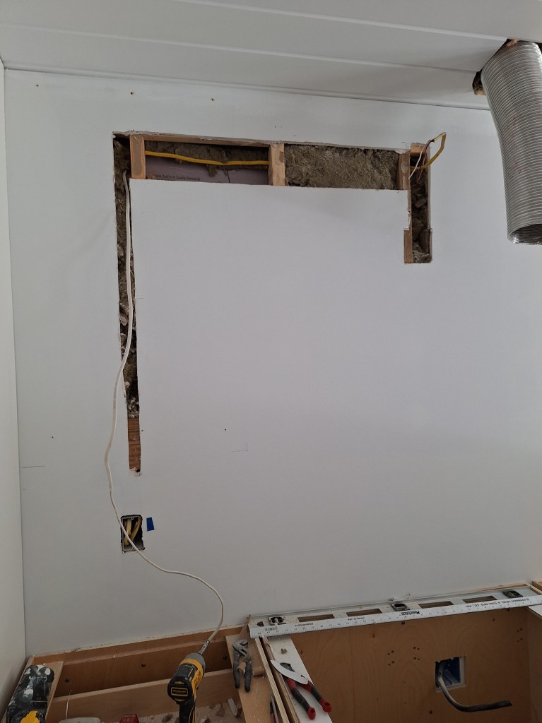
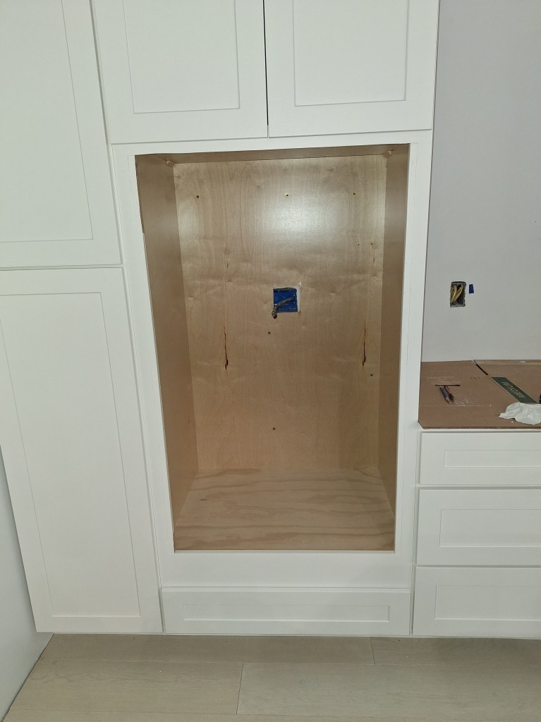
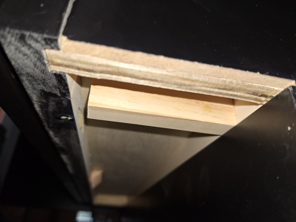
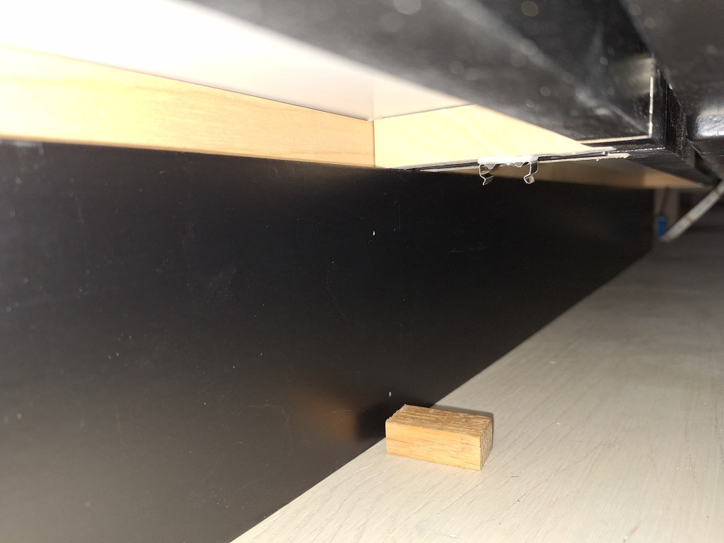
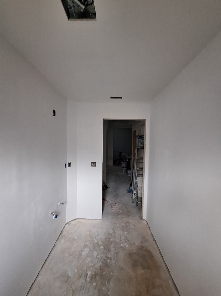
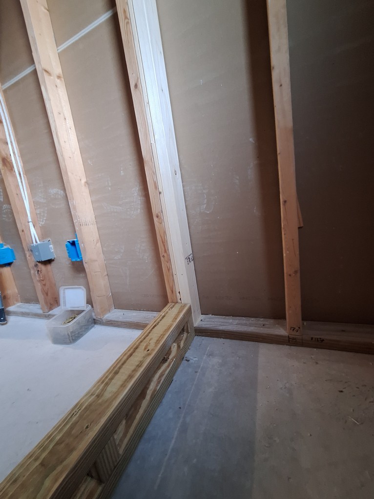
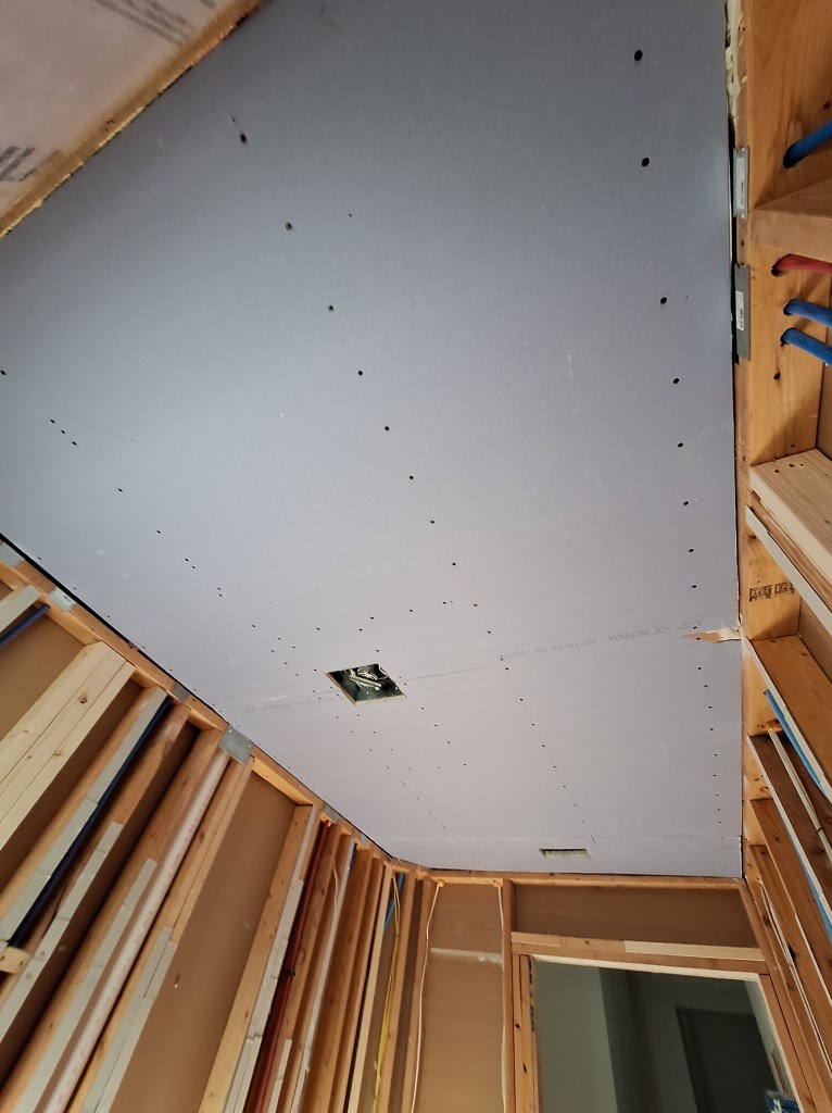
Note the opening in the ceiling. When I had the underside of the roof deck insulated with spray foam, they walled off the area between the garage and the rest of the house to separate the conditioned space from the unconditioned space. This meant that I no longer had access to the attic by using the original opening within the garage. The opening you see in the image above was created as a temporary alternative. I have since relocated the access to the attic to the area between the two closets in the master bedroom. Consequently, in the image below, you will see it closed off as I added drywall. As with the laundry room, I used off-cuts of drywall, so it too is a patchwork.

Large Master Closet – Drywall Hanging Completed.

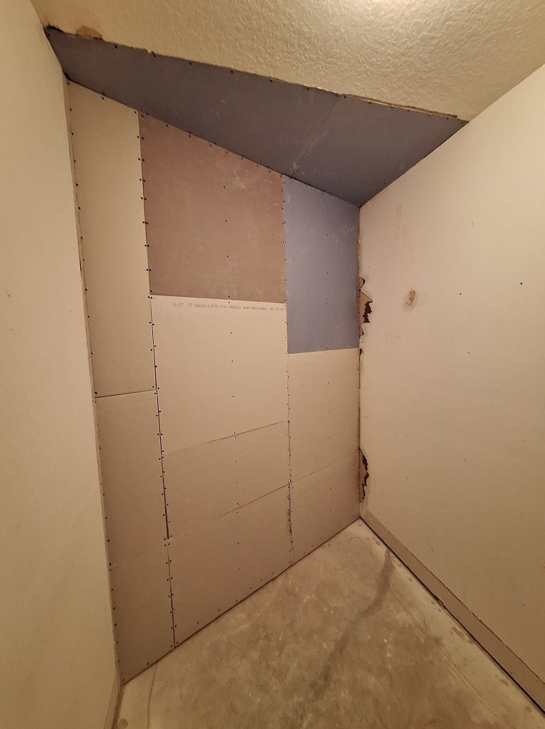
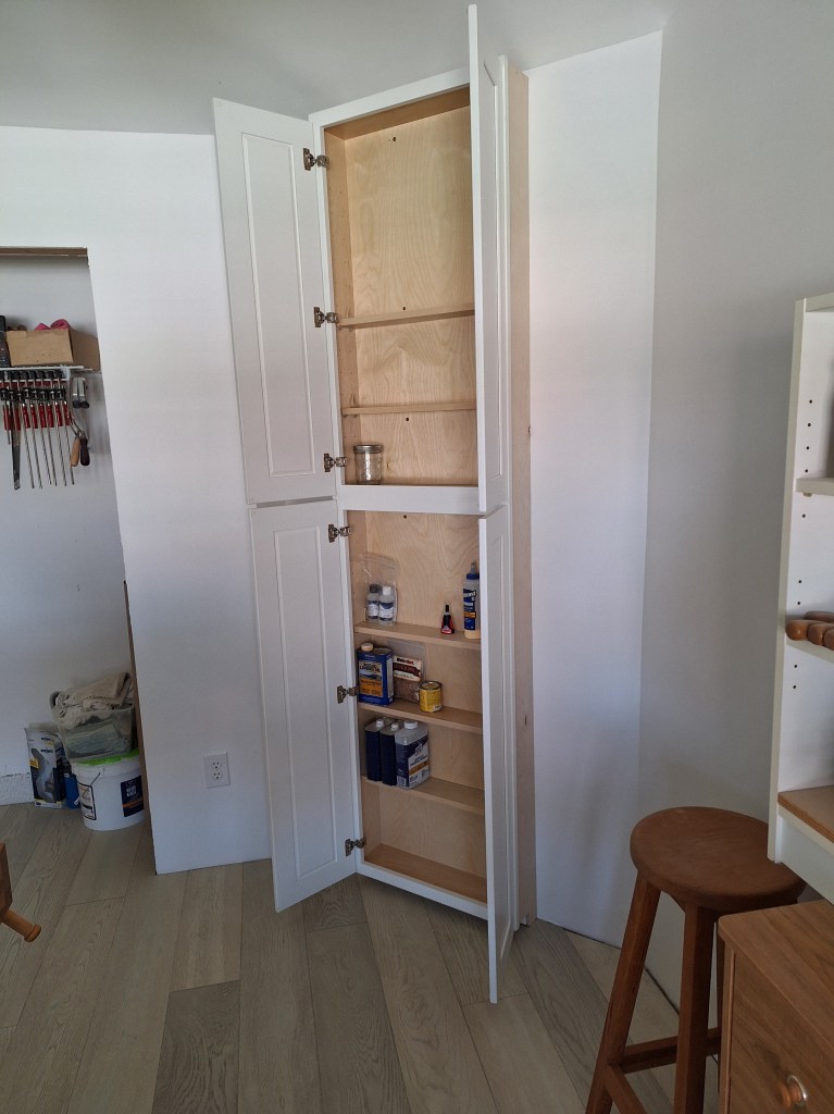
It’s pretty ugly, but just wait until you see it once I’ve finished. Eventually it will be covered by cabinets when I get around to spiffing up the closet. But that will be a very long time from now.

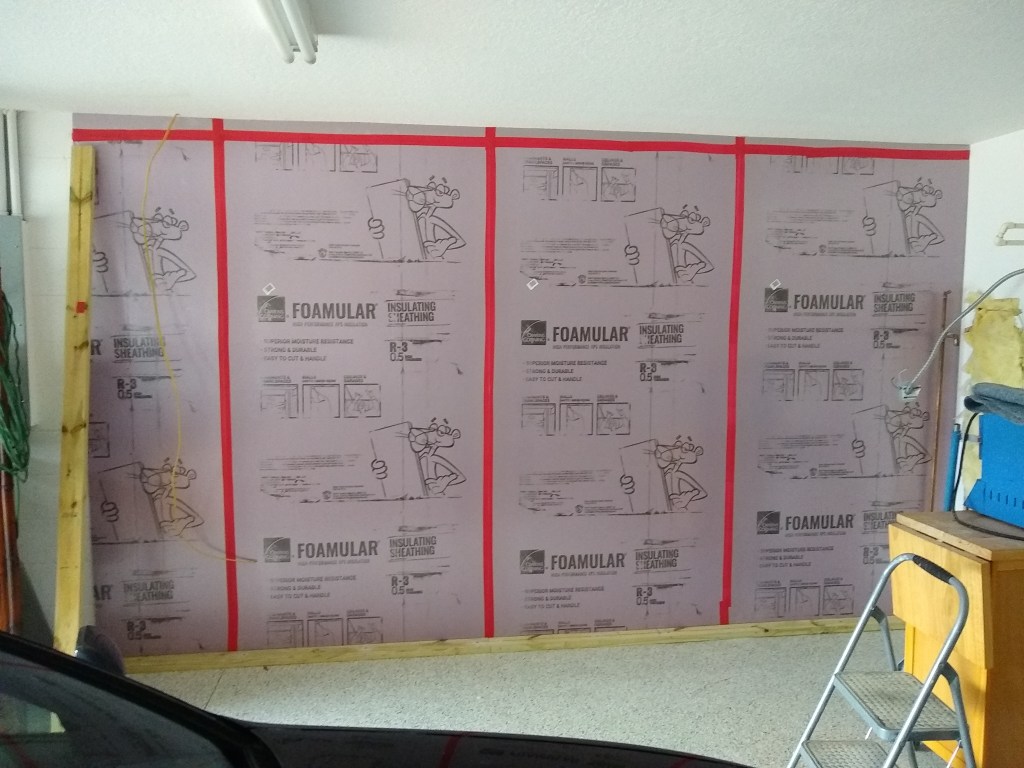
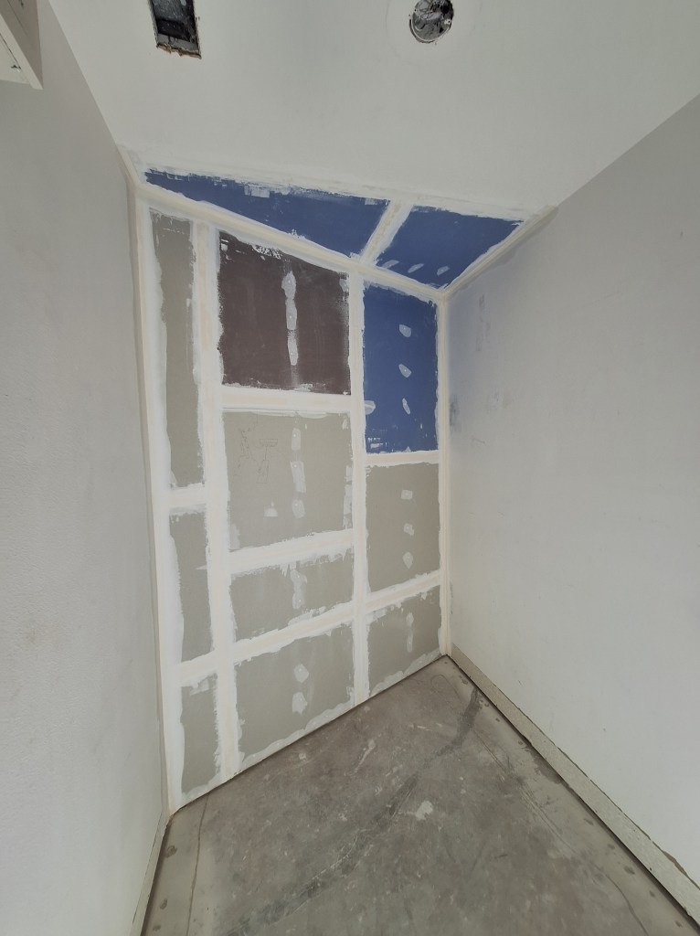
The inspection of both the large closet and laundry room went without a hitch, so I prefilled and started taping. Here it is after taping. I removed the light fixture in preparation for coating the ceiling, so I used a different light to illuminate the room for this picture, hence the whiter appearance.

Large Master Closet – Taping Complete.

I prefilled and taped the laundry room during that same period.

Laundry Room – Taping Complete.

I continued to work on both the laundry room and large master closet concurrently. The first coating of the tape was next.

Laundry Room – First Tape Cover Coat Complete.

I also applied a first cover coat to the ceilings in both rooms to begin transforming the knock-down texture to a smooth texture. I used an all-purpose mud for that. For subsequent coats, I returned to the light weight Plus-3 mud.

Laundry Room – Cover coat of Ceiling Complete.
Large Master Closet – First Tape Cover Coat and Ceiling Cover Coat Complete.

For the second cover coat, I decided to cover the entire wall surfaces rather than just the tape, since the coverage area was not so extensive. I did, however, add more mud over the taped areas to make sure they were properly covered before I started the proper skim coating phase. So, arguably, the second cover coat was a kind of skim coat, with emphasis on the taped areas. After the second cover coat of the walls, I applied the first of two skim coats to the ceilings.

Laundry Room – Second Tape Cover Coat of Walls, First Skim Coat of Ceiling.
Large Master Closet – Second Tape Cover Coat of Wall, First Skim Coat of Ceiling.

When skim coating, I usually apply two coats. However, I have had my doubts about the need for two skim coats, so I decided to try applying just one for the walls of the laundry room and large closet. I figured this was the place to try it because if I decide that two skim coats is the way to go, these rooms are where I can afford to learn that lesson. So here they are with just a single skim coat applied to the walls. The ceiling however, still gets two skims coats because of the heavy texture I had to cover.

Laundry Room – One Skim Coat on Walls, Two on Ceiling.
Large Master Closet – One Skim Coat on Walls, Two on Ceiling.

With just a single skim coat, you do not get the “almost painted” look. But the surfaces are smooth, so the coat of primer and two coats of paint will take care of the patchiness you see in the images. Here are the final results after two coats of paint to the walls and ceiling.

Large Master Closet – Two Coats of Paint applied to Walls and Ceiling.

For the closet, I used the same paint on the walls as I used on the ceiling. It is a flat Behr ceiling paint. I’m very happy with the result. However, in future I will go back to applying two skim coats, especially over a painted surface. You need an inspection light to see, but when you skim a painted surface, it can leave very tiny air bubbles. This is because the water in the mud cannot be absorbed into the painted surface. As such, it’s only way out is in the other direction, resulting in tiny bubbles. These bubbles are not always apparent when skimming. It was not until the next day while priming that I noticed them. They are sufficiently insignificant that I decided not to address them, especially given that this is a closet and that the walls will probably be covered by cabinets some day, as mentioned previously.

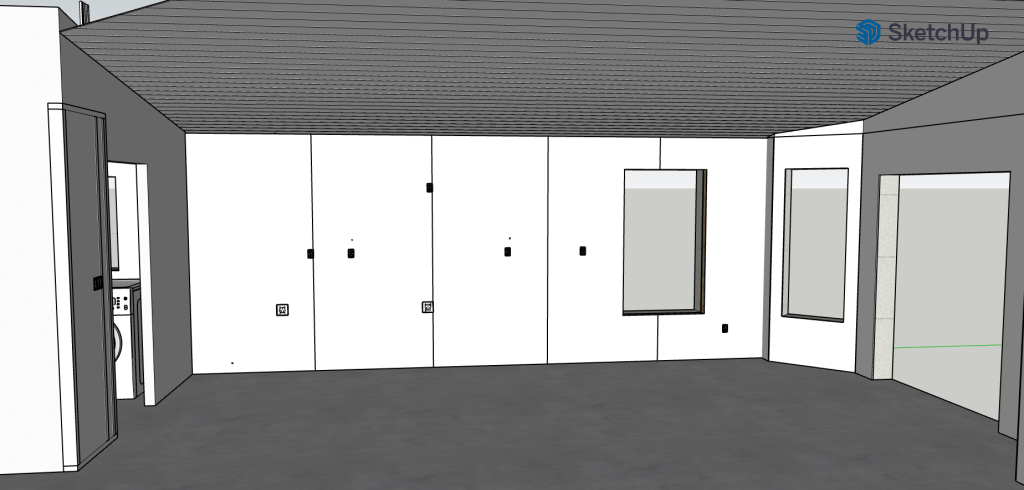
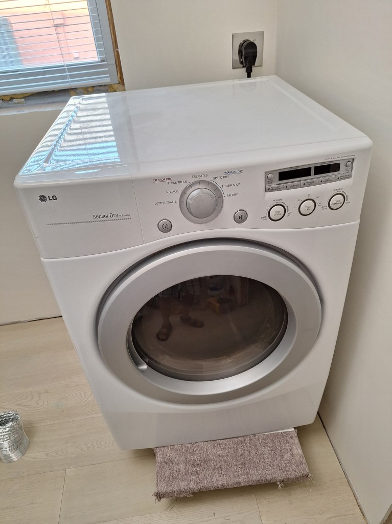
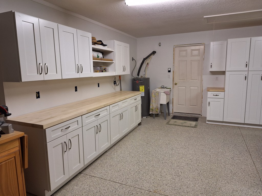
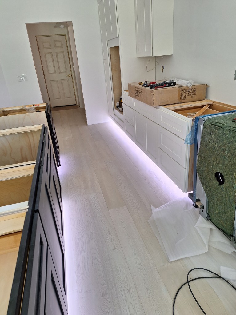
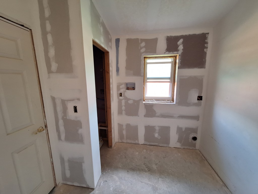
For the laundry room, I applied two coats of Behr ceiling pain to the ceiling and two coats of Behr Dynasty White Palais with an egg shell sheen to the walls. It took several samples before I settled on the wall color, but I am very pleased with it. It’s actually what I was going for in the bedrooms, but I’m not going to go back and change them now.

Laundry Room – Two Coats of Paint applied to Walls and Ceiling.

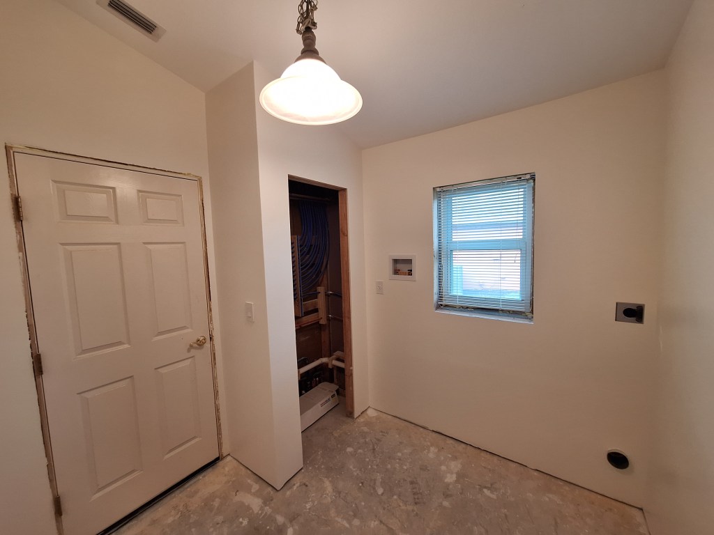
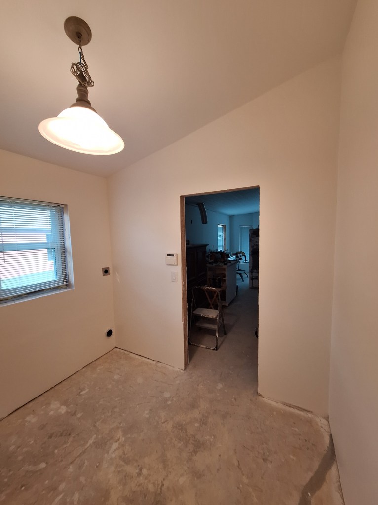
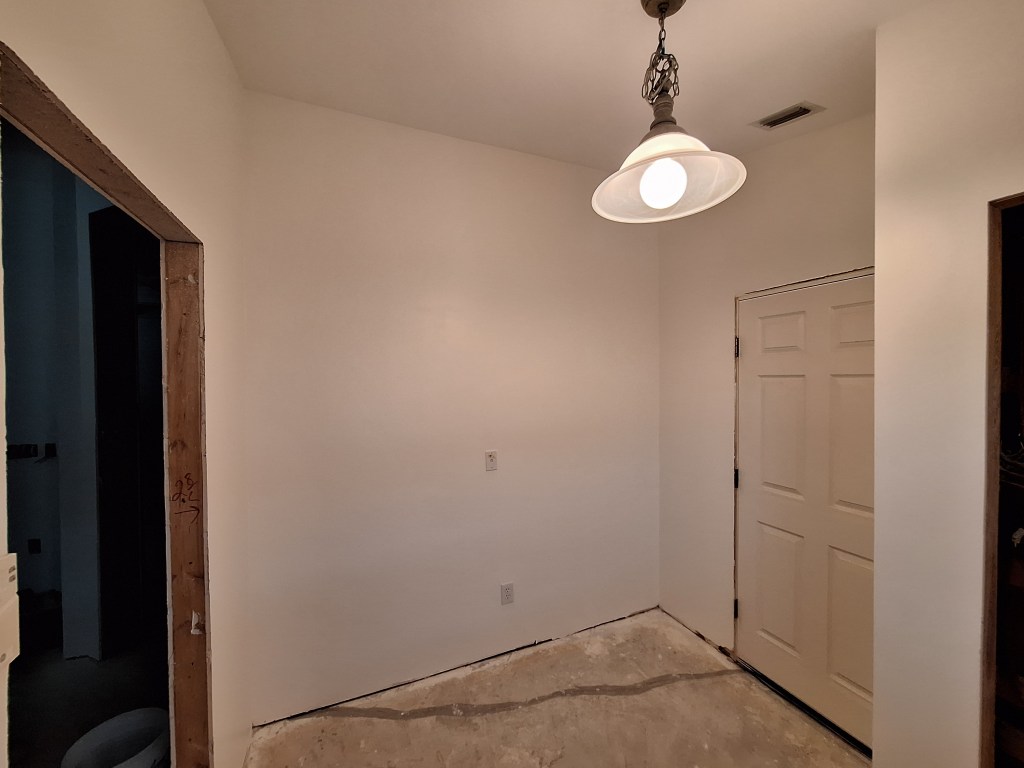
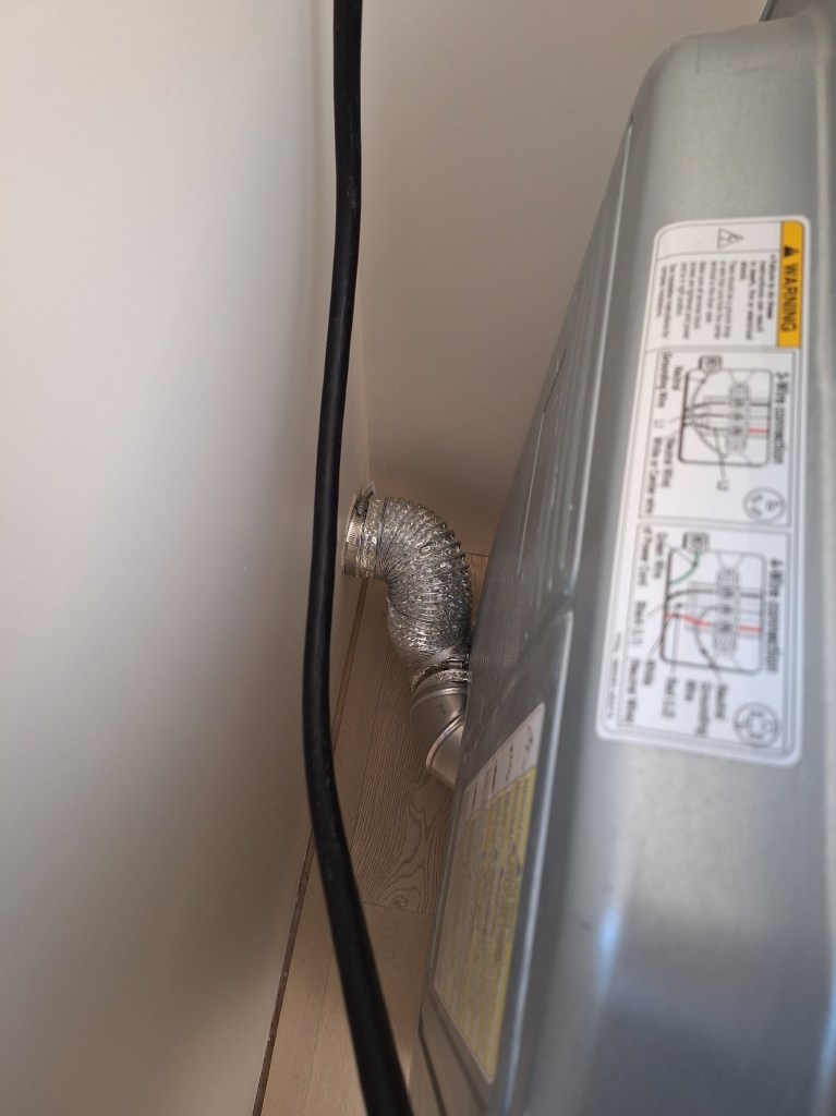
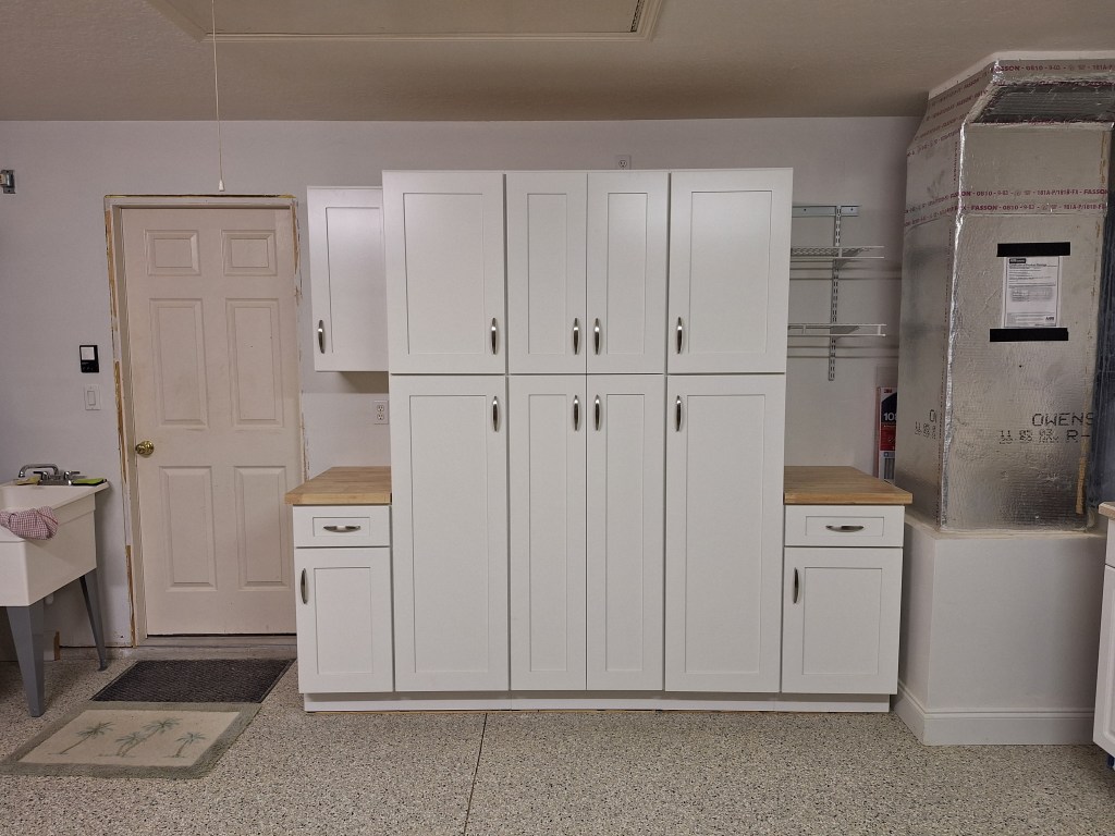
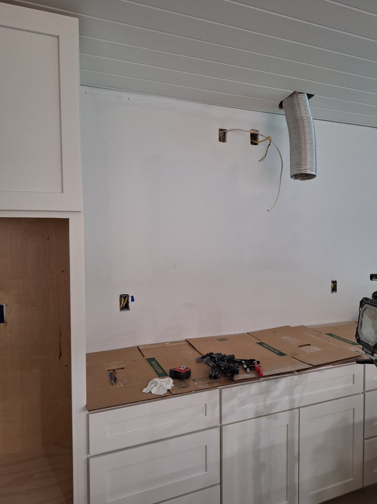
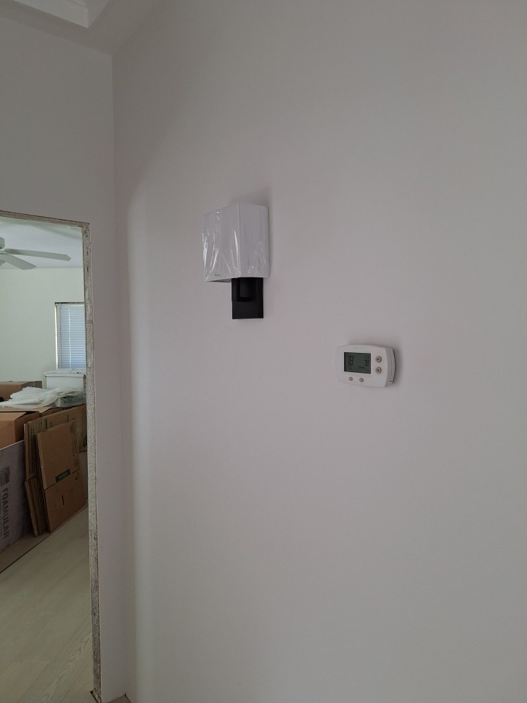
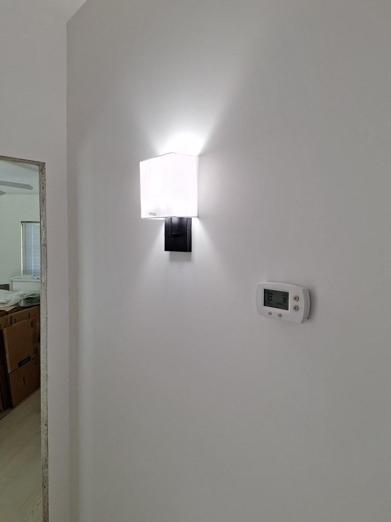
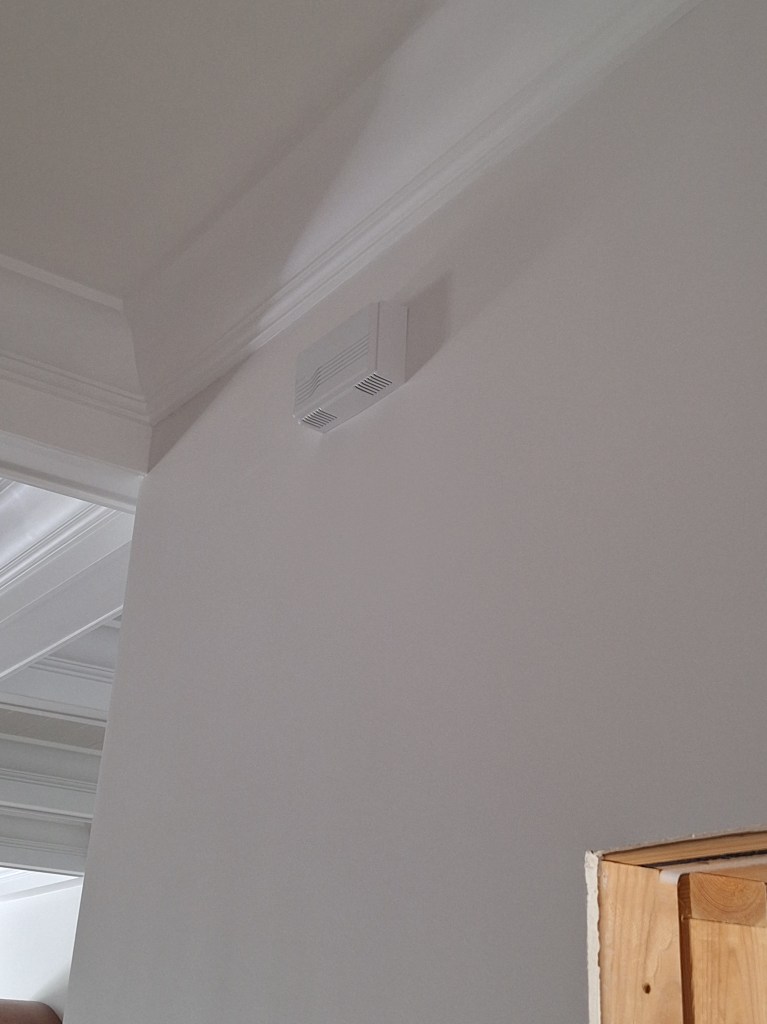
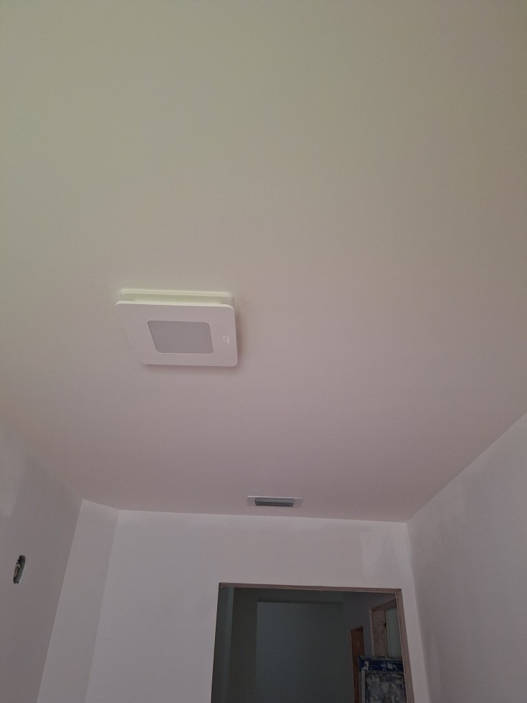
All the electrical outlets and switches are installed and working. The lamp you see installed is a temporary measure. I have another in mind, but haven’t quite found what I’m looking for yet. The lamp I installed used to hang above the kitchen table when the house was first built. This will be fine for now and I may hold off on replacing it until I’ve moved in. I also added spray foam around the door jam to the garage to prevent air flow. As the weather heats up, this will be helpful.

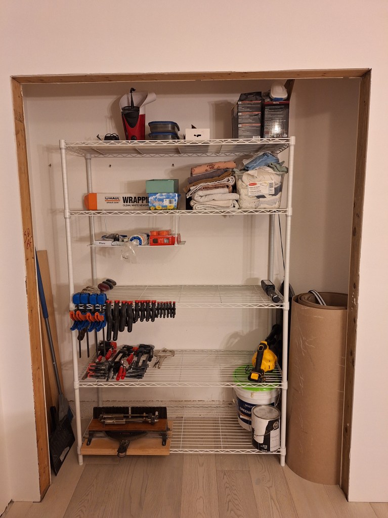
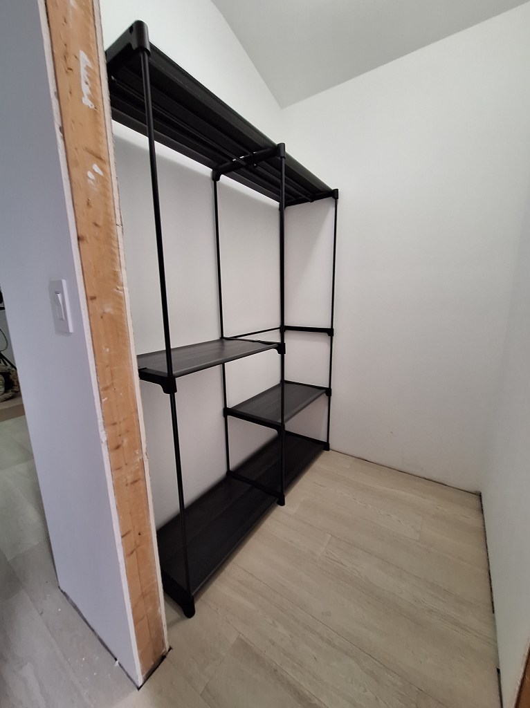
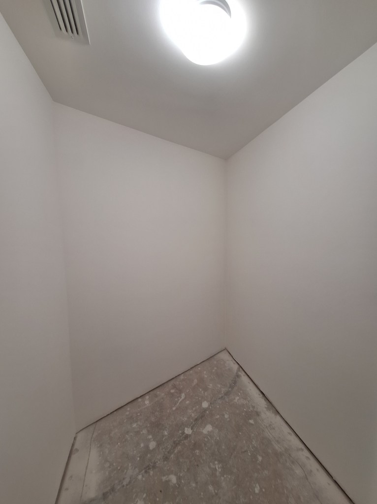
With the laundry room and large closet in the master bedroom done for now, I started work on the small closet in the master bedroom. This only required I removed the existing shelves and fill the holes before I could start coating the existing drywall.

Small Master Closet – Prepped for Skim Coating.

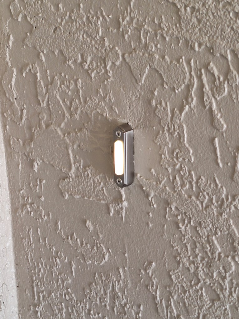
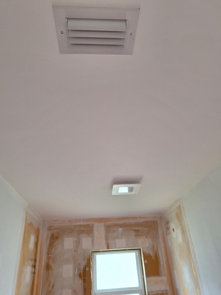
As usual, I applied a coat of all-purpose mud to the ceiling to cover the knock-down texture. After that I applied two skim coats to it and the walls to smooth them all out. With two skim coats, there were no tiny air bubbles to contend with. The surfaces looked great and were ready for two coats of the flat white ceiling paint (same as what I used in the large closet). It would make no sense to show a series of images capturing the progression because it would not come through. It would just look white at each stage. So here are a couple of shots of the closet after I applied two coats of paint and reinstalled the switch, light, and A/C grate.

Small Master Closet – Two Coats of Paint applied to Walls and Ceiling.

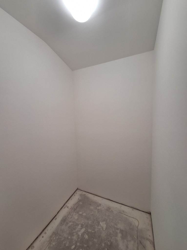
I think it looks great. The funny thing is, no one other than me will appreciate it because who actually notices such things. Still, it pleases me.

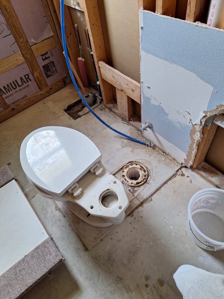
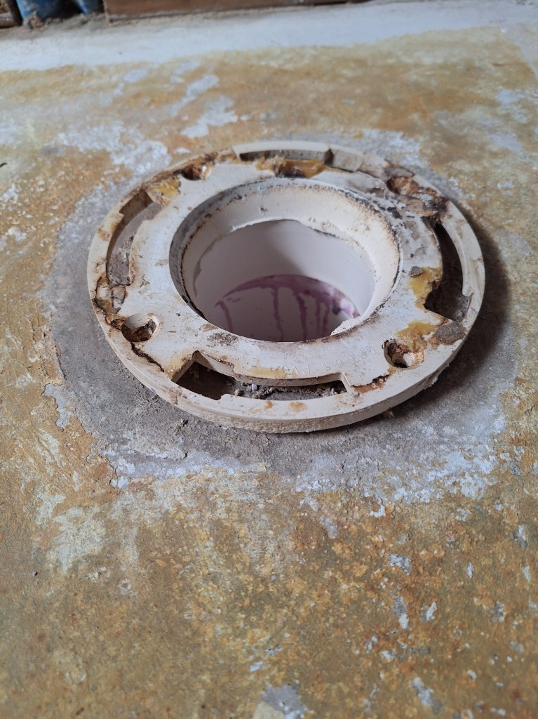
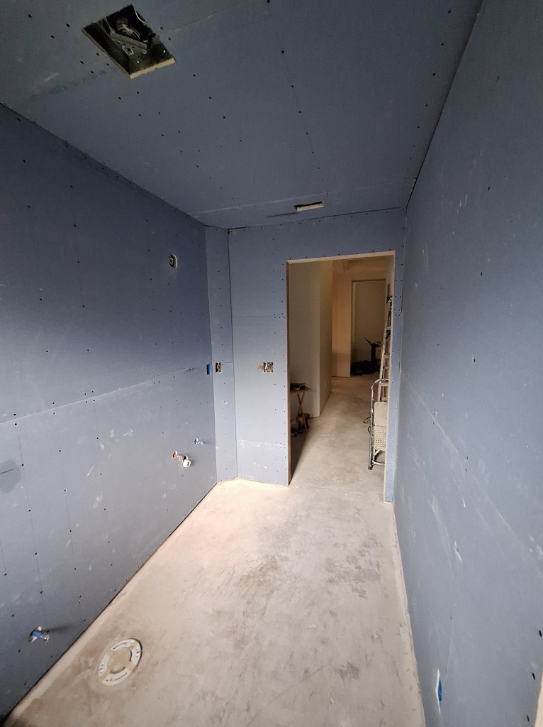
The only drywall work I have remaining is in the guest bathroom, so I’m getting close to the end of the messy work. Since the only functioning bathroom I have at the moment is the guest bathroom, before I start to work on that, making it unavailable, I need to get the master bathroom functional. So that is my next order of business. That will be the subject of the next post.

Featured

Framing Continued – September 2022

In the last post I just finished framing the exterior wall of the master bathroom. My next job was to clear out the tools and such from the master bedroom and get to work framing its three exterior walls I imagined the job of clearing out the master would be a big one, but it didn’t take me too long, so I was able to get right to putting up the foam board on the south wall.

South Wall with Foam Board

As you can see, I used some of the many 2x4s to help keep the foam board pressed against the wall as the adhesive takes hold. I also put down the pressure treated 2x4s that attach to the concrete slab with tap-con screws. While doing that I realized that I had to put up the foam board for the adjacent walls in order to get the dimension for the pressure treated boards correct, since they would be butting up against the foam board on those walls too.

The next day I returned to do the actual framing of the south wall.

South Wall Framed

The next day I started on the west wall and managed to get the foam board up and half the wall framed. So I was getting faster.

Foam Board up on West Wall
West Wall Half Framed

Having made good progress the previous day, finishing up the west wall didn’t take long the next day.

West Wall Framed

Although I made quick work of the remainder of the west wall, I could not start on the east wall of the master because I had to install a spigot on the outside of that wall, and for that I was waiting for the delivery of a special drill bit to create a 1-1/2″ hole through the concrete block. Not wanting to end my day early, I turned my attention to the garage wall that will receive cabinets. As usual, it begins by putting up the foam board.

Foam Board up on Garage Wall

You’ll also notice if you look closely, I fed the electrical wire down from the ceiling. This will power the outlets along that wall. The next day, I framed it.

Garage Wall Framed

The day after finishing the garage wall, Jennifer (the interior designer) came to the house. We had a good chat. The next step was for her to send me a proposal of the services they would provide, which should arrive in the next week or so. In the meantime, I would continue with the framing.

While working on the garage wall, the 1-1/2 inch coring bit I ordered arrived. That was nicely timed, as it allowed me to return my attention to the east wall of the master bedroom. I was a bit apprehensive about drilling out the hole for the spigot. I’d never drilled such a bit hole through a concrete block wall. I did a lot of exploring online and it seemed straight forward enough, but there is something unsettling about drilling a big hole in your exterior wall. But it all went very well. I fashioned a little jig out of a piece of 2×4 lumber to prevent the drill bit from wandering as I tried to get the hole started. Below you can see the jig and the long coring bit attached to the drill.

Hole Drilled – Outside View

I kept the jig in place using my foot as I pushed the spinning coring bit into the wall. Once the hold was started, I was able to remove the jig and carry on. While drilling I used a hose to keep the hole wet. The drill bit is a hollow steel tube with diamonds on the end. It was originally painted red, but as you can see, that didn’t last long once drilling started. I would push the drill in for a bit then pull it out and spray some more water in. It went quite well and it didn’t take long before I was through to the other side (about 8″).

Hole Drilled – Inside View

I was happy with the result. It left a nice clean hole. I fed the new spigot through from the outside and it extended just the right amount.

Spigot Installed – Inside View

And here is what it looks like from the outside.

Spigot Installed – Outside View with Cover Open
Spigot Installed – Outside View with Cover Closed

You’ll notice that the old spigot that is attached to the copper piping is still in place. That will just twist off and I will replace it with a cap, which I’ll eventually paint to match the exterior color, so it won’t be too noticeable.

You’ll also notice that the new spigot is kind of different from what you’re used to. it has a separate male attachment that connects to your hose and plugs into the opening revealed when you raise the cover.

How the Aquor “wall hydrant” connects.
Connected

When looking for a spigot to buy, I came across this and was impressed. It prevents anyone from making use of your water unless they have the appropriate attachment. I will add another one to the west wall, but will not replace the one on the east wall because it is attached to the main supply line, before the supply line feeds into the PEX manifold. So I’d have to take extra steps to take it out of the loop. For now, I don’t plan to do that, but I may change my mind once I’m moved it and fancy another project.

With the spigot installed, I could now return to framing the east wall of the master. And here is the result.

East Wall Framed

As far as I am aware, that is the bulk of the framing complete. I still have to create the closet in the laundry room for the plumbing, but that will wait until after the drain to the laundry tub (to be located in the garage) is hooked up.

Next, I turned my attention to repairing the framing of the kitchen extension. This was a job I was not looking forward to. The extension wall, although plumb, was not properly done (I didn’t do it). Two of the three vertical studs did not line up with the studs of the existing wall. If left alone, the drywall would have a slight but noticeable bend. So I had a lot of shimming and trimming to do. On one side of the each of the two studs I had to fill in the concave part of the bend, while on the other side I’d have to chip away wood to ease the convex part.

What made this so tricky was that the shimming was not uniform. It tapered along the lengths of each stud. To make this more manageable, I did each stud in sections. The studs are about 10 feet tall, so I created three separate shims to make up that length. Using my table top 4″ jointer, I planed down each shim a bit at a time, then took it to the wall to see how it fit. I did this over and over again until it lined up with the studs to the right of it. Once satisfied, I used wood glue and a lot of clamps to hold it in place.

Shimming a Stud

Here you can see two of the shims clamped in place. The shims are from left over furring strips I had, so they are wider than the 1-1/2 inch ends of the studs, but that was okay. The extra width didn’t do any harm. Below is an image taken after completing the first stud (it’s a bit blurry, but you get the idea).

On the other side of the stud I used a jigsaw to make horizontal cuts to the appropriate depth every quarter inch or so all along the length of the stud. To determine the depth of each cut I used a level to determine how far out the stud projected relative to those of the existing wall, creating a series of marks over the length of the stud. I then “connected the dots”, so to speak, producing a line at which I could aim. Note that this is just rough framing that will be covered with drywall, so it didn’t have to be precise. It just had to be close, so this approach worked fine. I then used a hammer and chisel to chop out the wood between the cuts. I did not get a picture of the result of this because there was not much to see. I suppose I should have taken a picture or two of the process, but it was a lot of work so story telling was not on my mind. So this is how I went about correcting the misaligned framing. Below are images of the end result with clamps removed.

Shimming Complete
Closeup of the Overhead Section

The overhead section did not require a shim over its entire length. It gradually lines up, so the shims you see above taper down to almost nothing. This means it is a bit wider at one end than the other. I don’t think this will be noticeable once the drywall is up and finished. If it is, then I will address it with trim.

At this point I believe I can call for a framing inspection, which I’ll do next week. While waiting on that I have another error to fix. Something I messed up. I’ll report on that in the next post.

Featured

Permitting – March/April/May 2022

As mentioned in the previous post, I decided to apply for the permits I will need rather than involve a general contractor. In this post I will detail what I did and the experience.

On February 24th, I made a trip to the local permitting office. They explained that I needed to fill out two documents. The first one is an owner/builder affidavit where I acknowledge that as the “general contractor”, I agree that any sub-contractors I hire will be licensed and insured. It also spoke to a few other things like my responsibility to any employees I bring on, which will not apply in my case. The second document was the permit application. In it I was to explain the scope of the work along with the estimated costs. I filled that out as best I could, but provided separate documents to provide details. Here is the description of the work I provided:

Accompanying the description, I provided printouts of selected views of the 3D SketchUp model I created. Learning to use SketchUp took some time. Between that and the many trips to the house to gather the measurements needed to make the model accurate (accurate enough to be of value), it took several weeks to complete the model. I submitted the application on March 21st. Although it took a lot of time, I’m glad I made the effort. SketchUp is a very useful tool and one I will use in future when modeling anything I intend to build.

For the model to be truly useful to me, beyond providing pictures for permitting, it needed to be based on relatively accurate measurements. I know the measurements weren’t perfect, but accurate enough that I was able to really play with the rooms to understand what would fit and experiment with different ideas, all without spending a penny nor lifting a tool. It also made it much easier to create an accurate bill of materials before I go shopping. Here are some of the pics I submitted to the permitting office.

Top
Front
West
Back
East

There were more images submitted, some with greater detail, but from what I have shown above, you get the idea.

I submitted these documents on March 21st and then waited. During that time, there was little I could do on the house without a permit, so moved back into the garage some of the things I had stored in the house while the garage floor was being done. I also identified and marked the wire in the attic above the garage that will be used for the new garage outlets. Of course, those were just a couple of small jobs, so I got a bit impatient and decided it was of minimal risk to do a little more demolition. So I pulled off the strapping exterior wall in the laundry room, the master bath, and master bedroom in preparation for framing them.

After hearing nothing after almost three weeks, I sent an email on April 5th inquiring about the status. The next day I was told the application was rejected because the application form I filled out had a page that was for a different city. That is, the form that they handed me and highlighted was, presumably, the wrong one. So, there are two issues with this. The first was that I filled in the documents they provided. Secondly, they never contacted me to let me know there was a problem. So I went to the permitting office the next day (April 7th) to address it. I spoke with the fellow to whom I handed my application (40+ pages) almost three weeks prior. He remembered the house, but could not, at first, find the documents. That was very disconcerting given that it cost me quite a bit to get so many color printouts. Eventually he found them (whew!) and discovered that the problem with the application was not as described to me in the email. It was simply that I did not provide an estimated cost for the electrical and plumbing work. I updated that then handed it back.

On April 18th, I got a response from the permitting office that I needed to provide an electrical plan and details about the slab cutting and subsequent re-filling. So I got onto Google to find out what an electrical plan was. The electrical plan is a 2D floor plan that identifies how the house is to be wired. So my first thought was that I would update my 3D SketchUp model to add that information. Although it can be done using a SketchUp extension, what was required to make that happen would be overkill. So I looked for another software solution and chose a product called EdrawMax. It required a $69 six month subscription, but was better tailored to the task, so I signed up.

So yet another software tool I had to learn, but it was pretty good and gave me what I wanted. I completed the electrical plan April 28th, so about a week’s work once the tool was chosen and installed. Here is what I submitted.

The above image just shows the electrical plan for the kitchen and bath rooms. That is all they requested. But I decided, since I was at it, to create a plan for the entire house, which would be useful for me. It’s a bit busy, but here is the full plan.

With this I am able to identify what devices each breaker covers, so I’ll be happy to have this on file.

As mentioned above, I was asked to submit a cross-section of what will be done when filling in the parts of the concrete slab I cut out. This is what I created.

Both the cross-section and electrical plan for the kitchen and baths were submitted on May 2nd.

I got a response on May 5th expressing concern about the access to the toilet in the master bath and asking for information on the French doors to the lanai. I discovered that I made a mistake when transferring the measurement from the 3D SketchUp model to the 2D floor plan, which made the entry to the toilet alcove seem narrower than it should be. A good catch on their part. So I corrected that. Note that what I show above is the corrected floor plan. In the original I had it about a foot too long. As for the French doors, I informed them that I was not looking to permit that, as it was done professionally last year and the installers took care of the permitting. I sent my response on May 8th.

On May 12th, I got an email informing me that the permit had been approved. Woohoo! On May 13th I picked up the permit and displayed it in the front window of the house.

While waiting for the permit, I decided I would look for someone to cut (re-cut) the slab. I have to open that up again and make changes so it passes inspection. In the original effort, no soil treatment was done, nor was any vapor barrier added. Also, the wires I ran to the island needed to be enclosed in a conduit and one of them needed to be a larger gauge (12/2 instead of 14/2). So these mistakes necessitated a redo. Not only that, but an inspection will be needed before the holes are filled in. The one thing I was not keen on redoing myself was cutting into the slab and having to break up and dispose of large chunks of concrete. So after picking up the permit I scheduled a crew to come in and do that next week. So it looks like I am finally back in business.

Featured

Delays and Garage – January/February 2022

At the end of the last post I mentioned that I would be meeting with an electrician to discuss adding a 240 volt line for the cook-top. That meeting changed a lot. We had a really good chat and he was kind enough to educate me about permitting. He walked through the house and pointed out a number of things that I should be aware of, but most importantly made me realize that I really needed to get permits for the work I have been doing. Many people proceed with interior remodels without permits, but they really shouldn’t. In my case, the changes were so significant that I really needed to follow the process and have proper inspections done. Even though I have no plans to sell the house, one never knows if that will change. If I do decide to sell, the massive renovations that were performed without permits/inspections could cause problems.

This may seem rather obvious, but I was following Chris’ lead on this and he did not want to go down that road. After my discussion with the electrician, I understood that I was skirting the system, and I was not comfortable with that. I decided it was time to set it straight. So I started looking into what was required to get permits. I called the permitting office and they filled me in. I could sign an owner/builder affidavit that allowed me to be my own general contractor (GC), with the understanding that I was responsible for hiring fully licensed and insured contractors. For work I would do, I had to apply for permits myself. The idea of having to wade through the bureaucracy was not appealing, so I started to entertain bringing in a general contractor to manage it and even hand off some of the work. Although this would cost considerably more, the benefit would be that the work would get done sooner and I should be able to move in before the end of the year, thus avoiding the need to renew my apartment lease.

I contacted three different GCs. One fellow, we’ll call him GC1, was busy but would call me the following week to discuss further. I made appointments to meet the other two. The first fellow I was to meet, GC2, was late. I eventually texted him and he somehow lost my information. My text was what allowed him to find it (?). So he eventually showed up and we did a walk through. As we spoke, I got the impression I only had half his attention as he seemed more interested in his phone. Although he claimed his firm could do everything I wanted, I told him I had other GCs to speak with before I made a decision. As you might guessed, I did not choose him. He did not make a good first impression. The next fellow, GC3, did make a good impression. I liked him and was happy with everything he said. The next step was to bring his engineer in to get drawings together and discuss the plan. I still intended to do as much of the work as possible, but we would figure out who would do what. I told him I would get back to him, as I still had one fellow (GC1) to hear from. GC1 never got back to me, so I let GC3 know that I wanted to work with him. We made an appointment to meet again, and he would bring the engineer with him. To make a long story short, the engineer canceled three separate times. GC3 was embarrassed and was genuinely apologetic. He was going to find another engineer and get back to me. More than a month later, I have still not heard from him. I’ve been abandoned.

Around here, this industry has a reputation for not being reliable. It’s sad, but I’ve heard so many stories about this. So I decided to look further into what it would take to apply for the permits myself. This would require creating construction documents or something deemed acceptable. So I would have to learn a software drawing tool that would allow me to produce such documents. I started learning SketchUp. I’ll get back to that later.

In the meantime, I wanted to do something in the house, so I turned my attention to the garage floor. I expected to do that near the end of the renovation, but since it did not require permitting, I decided to move forward with it. I decided to hire someone to do the work so that I could continue learning SketchUp. I was really happy about that decision because I was delighted with the result.

I moved all the stuff from the garage into the house in preparation for the guys who would be doing the job. I chose an epoxy covering with “full flake”. This would seal, protect, and provide a non-slip surface.

The process began by grinding down the concrete surface and filling any cracks.

Next they applied the base coat, starting with the perimeter then filling in the middle.

Once the base coat was down, it was time to apply the flakes.

Lots of Flakes

They started by distributing the flakes around the perimeter then worked on the middle, from the back to the front of the garage.

After fully distributing the flakes, this is what it looked like.

Flakes Applied

That was left for about an hour before they started on the clear coat.

Here it is after the clear coat was finished. I love it!

Clear Coat Applied

And here is another from inside the house. You can get a better sense of the gloss from the clear coat as it dries.

Clear Coat Still Wet

I left the garage door open a bit until the next morning. I could walk on it later that night, but did not. I decided not to walk on it until it was safe to drive on it, which would be three days. I’m happy to report that this job exceeded my expectations. I’m so glad I hired someone to do this.

This job only took about three hours to complete. I was amazed. My neighbor came by and ended up having them do the exact same thing (color and all) to his garage floor. It did take a couple of weeks before they were able to do the job, one of those weeks due to bad weather. During that time I was busy learning Sketchup, starting by modelling the way I wanted the garage to look. Here is what I came up with.

Front Facing
Looking to the Right

In the image above there are a couple of wall cabinets sitting where the A/C air handler sits (not modeled). I don’t have a spot for them, so I just put them there for now.

Looking to the Left

Before putting the other house on the market, I was going to replace the kitchen cabinets to entice buyers. So I purchase the cabinets at the end of 2019. Almost two years later when I finally put the house on the marked, housing prices took off, so my agent felt there was no need to replace the cabinets. As a result I decided I would use them in the garage of this house, which is what you see above.

These cabinets required assembly, so after the floor was done and drying, I used the time to assemble the cabinets and move them into the garage for the time being. The first one always takes the most time because I’m figuring it out. I started with the 24″ base cabinet (B24), shown below. Notice all the other cabinets in boxes in the background.

My First One. B24.

The next day I assembled the 15″ and 18″ base cabinets (B15 and B18). So getting faster.

Once B15 and B18 were done, I moved them into the garage into the position I will eventually attach them.

The next day I assembled four cabinets: two 30″ base cabinets (B30), the sink base cabinet (SB33), and my first wall cabinet (W30). I moved these into the garage and placed them along the wall opposite to where they will go because I will need them out of the way so I can frame the wall upon which they will be attached.

The following day I assembled W15, W24, W30, and the first 18″ pantry cabinet (P18).

I was missing the 24″ pantry cabinet, which is supposedly on its way, so I only had the second P18 left to assemble. I did that the next day. The missing 24″ cabinet (P24) will fill the opening between the two P18s.

There was a lot of cleanup to do after that, which I got to promptly. Now I am in a holding pattern, with respect to work inside the house, until I get permits. I’m busy modeling the house with SketchUp, which will require a lot more work as I add detail. In the meantime, here is a sneak preview.

Floor Plan

The above image is of the overall floor plan. The garage details shown earlier are not part of this model. I will keep that separate. Below is detail of the plumbing (see past post for the actual work). I intend to capture this sort of detail for all the changes I have made and will make. This will take some time, so I will pick away at it until I have modeled everything I feel is needed by the permit office. Even then, I’m sure they will ask for more. It will be a learning process.

Plumbing in Laundry Room

I’m not sure when I’ll be able to resume work on the house. My priority now is to continue modeling and get my permit applications in. How long it takes to get approval is a big question. It will probably involve some back and forth. Hopefully the next post will shed more light on this process.

Moving In – October/November 2025

Following the installation of the stainless steel backsplash in the kitchen, the house was in a state where I could move in. Obviously there was still a lot to do, but all the things I needed to function were in place. I would spend most of my time preparing for the move. This meant a ton of sorting and purging, and eventually cleaning in preparation for moving the furniture from my apartment. In this post, I do not intend to cover that part of the process. Instead I will focus on the other things I attended to in between those activities.

One of the first things I did was to acquire a vanity for the guest bathroom.

Vanity Set in Place
Vanity Set in Place

As you can see, I opted for a free standing unit. The vanity you see above is simply placed where I want it. It has not been secured in these pictures because other things in the bathroom need to be installed before I secure it (like the baseboards). I will be replacing the door handles on the vanity to match the other hardware in this room. These handles are what came with the unit.

Another thing I attended to was getting a console table for the foyer. I found something online that I thought looked pretty good, so I ordered it and assembled it.

Console Table for Foyer (first attempt)

Although I liked the style, I thought it looked a bit small for the space, so decided not to use it there. However, I got the idea that it might work well in the kitchen at the end of the island as you enter from the garage.

Console Table in Kitchen
Console Table in Kitchen – drawer open.
Console Table in Kitchen

I was very pleased with this arrangement. I will be entering the house mainly from the garage, so when I do this will be where my keys will go, along with any other things that one typically places on the counter as you come and go. This provides a very nice landing zone, keeping the counter free.

Of course, I still needed something for the foyer. Then it occurred to me that I could use the table I’d previously used as a sofa table. I moved it into position and was immediately pleased with how it looked.

Console Table for Foyer (second attempt)

This is a bit more substantial and I like the combination of metal, wood, and glass. I added a mirror to complete it.

Foyer Mirror

The screening that encloses the lanai out back was in need of replacement. A couple of the screens had been missing for some time, so I decided to attend to that. I chose to outsource this work to make it quick, but I had to prepare for that first, which meant removing the existing screening so that I could wipe down the aluminum cage, which had a lot of mold built up on it from neglect. I also pressure washed the floor, which cleaned it up, but it needs a lot more attention and I have yet to decide what I am going to do there.

Removing the Old Screens

Here is a shot of the lanai after the old screens had been removed.

Original Screens Removed

And here is a shot from the same angle with the new screens in place.

New Screens Installed

The new screening has smaller openings than the previous screening. This is supposed to keep out the tiniest of bugs (often called “no-see-ums”). It was a bit more expensive, but I thought it was worth it. I want to be able to keep the doors from the house to the lanai open during nice weather and don’t want to have to worry about bugs getting into the house. Another thing I did along this line was to use spray foam to fill voids at the joints in the aluminum framing. Even with the previous screening in tact, the little lizards had a way of getting in. Although they are harmless, I prefer they stay outside. Since doing this, I’ve not seen a single lizard, so I think it has been a success. And what a nice view I have.

View on a Sunny Day

I also put up my wind chimes, which have been sitting patiently collecting dust for years.

Wind Chimes Hung

I like the look of the chimes, but positioned them in a protected location because they can get loud and I don’t want to disturb the neighbors.

Although the guest bathroom won’t be fully functional until after I get the baseboards down (a prerequisite for the toilet and vanity installation), nothing was stopping me from getting the glass shower enclosure installed. I hired the same people that did the glass wall for the master shower. For this installation, though, I added a door, since the area is much smaller. I was happy with the result.

Glass Shower Enclosure

Another chore I attended to just before the movers arrived, was replacing the two overhead lights at the front entry to the house.

New Overhead Lights

These fixtures are pretty simple. The original ones were looking a bit ragged, and I think these clean up the entryway nicely. Like the flooring in the lanai, I’ll do something with the entryway here. The bare concrete is not very nice.

The actual move took place on November 10th. The weather was perfect. The movers were great and made quick work of it, leaving me to arrange things the way I wanted them. This is what I settled on.

From Master Bedroom
From Kitchen
Looking North
From Foyer

I was surprised with how my traditional furniture worked in this room. It was my plan to replace all this and move toward a more modern look, but after setting it up, I was pleasantly surprised with the look. I really like it, so will be keeping my existing furniture. I already intended to keep the bedroom set. I bought it ages ago and have always liked it.

From Entry
Toward Lanai
Toward Great Room

Here’s the kitchen.

Toward Lanai
Toward Laundry Room

In my previous post, I showed a picture of the temporary rack I put in the laundry room to serve as storage until I built in cabinets and a bench. Here’s a reminder.

Temporary Rack – take 1

One evening while I was sitting peacefully in the living room, I heard a loud crash. I jumped up to investigate and discovered it was the shelf in the closet of the workshop. It came crashing down. I had been storing a lot of things on that shelf, including many clamps. I don’t have a proper picture of it, either before nor after, but here is one that will give you a small peek of it before it fell.

Peek at Closet Shelf on the Left

Fortunately, there was no real damage. I noticed a small ding in the flooring, but you had to really look to see it. After this, I decided that rather than put the shelf back up and ensure it was suitably secured, I would move the 5-tier rack from the laundry room into this space. I contemplated doing this when I first got the rack, thinking it would fit nicely here until I properly built out the closet, but decided it wasn’t needed. Ironic, eh?

5-tier Metal Rack Moved to Workshop Closet

As you can see, I have plenty of extra storage space available, so that is a nice benefit. The rack in the laundry room was replaced with a slightly smaller one since I didn’t really need all the space the larger rack provided. This one is made of plastic rather than metal, which is fine since it would not be supporting anything very heavy. Here it is loaded up with what I had before.

New Rack for Laundry Room

I am now living comfortably in my new home and am really happy about that. It’s really pleasant, which is aided by the beautiful weather we’ve had since I moved in, allowing me to keep the slider in the living room open most of the day.

There is still a lot to do. None of the trim work is done. There are no interior doors, and the crown molding in the kitchen has yet to be done. I’m contemplating hiring out some of that work, but will decide on that later. With the holidays approaching, I’ll be doing quite of bit of traveling, so until the New Year I am just going to enjoy my new home and take it easy. I’ll get back to work next year.

To end this post I’ll leave you with a picture I took the morning of November 25th from the lanai. I don’t usually get up so early, but that day I woke up as the sun was about to make an appearance, so I captured it.

Sun Coming Up

Until next year…

Preparations for Moving In – August, September 2025

After returning from vacation, the plan was to turn my attention to the garage workshop. The idea was to prepare for the upcoming trim work that was facing me inside the house. A lot of thought went into it, but no real action. I was considering getting several new pieces of equipment, including an 8″ jointer, a cabinet saw, and something for dust collection. Some of these would require new 240 volt outlets. The table saw and jointer are both large machines. I have limited room in my garage so both would have to be mobile so they could be moved to the side to make room for the car. After considerable thought, I decided to not buy anything, yet. Instead I decided I would see if I could make do with what I have and only buy something when not doing so becomes painful.

While that was going on, I decided it would be best to focus on the things that would have to be ready in order for me to move in, which would be mid November. Some low hanging fruit was adding hardware to the master bathroom.

Towel Hook
Towel Rod
Toilet Paper Holder
Shower Towel Hook

Since the towel rod is not right beside the shower, I added a hook to hold the towel while showering. I did not want to put a towel rod on the wall outside the shower because, if hung in the usual location, it would cover the switches.

Before moving in, I really needed to have the backsplash behind the cooktop installed. In the last post I mentioned that I planned to run the black granite up the wall. That was the plan, but the installers were really dragging their feet on this. I also asked them for an estimate for the vanity in the guest bathroom but, again, nothing. So while that was in limbo, I decided to have the tree in the front yard removed. It was something I figured I would do after I moved in, but given the limited activity, I decided to initiate that process. Fortunately, the company I contacted to do that was very prompt and responsive.

Tree Before Removal
Tree Before Removal

As you can see above, the tree was pretty ugly. Knowing it was going to be removed, I did not have it trimmed, so it was getting really crazy. It was a Live Oak, and was really not suited to this small a plot. The root system is extensive, so it would eventually mess up my driveway. Also, it sits atop the drain that leads from the house to the city sewer system, so that could be impacted too.

Tree Removed
Remaining Stump
After Stump Ground Down

I will leave what you see above until the spring before sodding that area. It needs to settle for some time.

Returning to the cooktop backsplash, I contacted someone else to get an estimate, since my countertop installers still hadn’t responded. I got a much higher quote. Shortly after that, I did hear from my countertop guy, and he was expressing some concerns about the weight of the slab for the backsplash. It would be a very heavy slab. So that got me thinking of alternatives, and I decided to abandon the granite and instead opted for an embossed stainless steel backsplash with a diamond pattern. It would look really nice, be easy to clean, and would not introduce any weight issues. So I found someone to do that work and initiated the process.

While that was going on, I took care of a small but nagging issue that needed to be done before I moved in; mainly adding the remaining Ethernet keystones and faceplates. I wasn’t looking forward to this because it is fiddly work, but I was pleased to have it done. Here are some of them.

Keystones 17 and 18, in Kitchen.
Keystone 21, in Master Bathroom.

Once each of these is wired up, they have to be tested for connectivity (I have a special tool for that). If the connectivity is good, then I plug in my laptop and make sure it connects to the internet. Once that it confirmed, I insert the keystone(s) into the faceplate and attach the faceplate to the wall. After that is done, I verify again that the laptop can get online. I do this second test because, when attaching the faceplate, the keystone gets pushed into the junction box, which can disturb the connections. Fortunately, that did not happen on any of my installations.

With that done, I hooked up the washer and dryer. They certainly need to be working before I move in. I started with the dryer because it needed a couple of modifications before I could use it. The first was to simply reverse the door. In its current setup, the door would swing open toward the washing machine, making it awkward to transfer clothes from the the washer to the dryer. That was a pretty simple operation. The other thing I had to do was change the way the dryer vented. In its current configuration, it would vent to the left (toward the washer). That needed to change so it would vent out the back where it could connect up to the exterior vent. This proved to be quite an undertaking.

Original Vent Location

To move the dryer vent from the side to the back required that I disassemble the dryer (really!). I found a YouTube video that walked me through it, so that was great, but far more than I was expecting. So I moved the dryer into the living room where I had more space to work and started opening it up.

Disassembly Started

What you see above is the top and front door assembly removed. The control panel is resting on the frame and drum. That was just the start. To get access to the vent, the drum would have to be removed.

Dryer Door and Drum after Removal
Drum Removed

With the drum out of the way, I had access to the area where I would install the vent pipe. Below you can see it installed.

Straight run of Pipe out to the back of Dryer
The turn after Exiting the Dryer

Something of note here is that the pipe that was installed before (the one that vented out the side) was very poorly installed. When I pulled it out I noticed that it was not sealed with foil tape. Instead, the installers simply lined up the sections of pipe as best they could and used foil tape to keep them together. Because they did not take the dryer apart like I did, they had very limited access, so they would have simply reached in as far as the arm would allow and tape the pipe sections together as best they could. They would not have been able to wrap the foil tape fully around the pipe, which is what I saw. Having no experience with this, I was oblivious. It worked, for the most part, but would have leaked a lot, which would have heated up the room, making my A/C work extra.

With the new section of pipe in place, I reassembled the dryer and used a flexible foil pipe to tie it to the section of pipe in the wall that leads to the outside.

Flex Pipe to the Outside

Here it is installed (sort of).

Dryer Installed (for now).

I turned it on, then went outside to verify that it was venting well, which it was. As you can see, I have kept it on the dolly. Since the dryer will have to be moved some day when I install baseboard, I decided to leave it on the dolly. A dryer doesn’t spin at a high rate of speed like a washing machine, so it doesn’t need to rest as securely on the floor. So this should be fine for the foreseeable future.

The installation of the washing machine was a much simpler matter. I did not need to make any modifications. I simply needed to remove the shipping bolts I installed before moving it from the other house, and then connected the water supply and lines put the drain pipe in place.

Washing Machine Installed and Running

Unlike the dryer, I could not leave this on the dolly. It needed to be on solid ground and level. To test it, I ran the “tub clean” program, which takes more than an hour. It was a good test and the tub was in need of a good cleaning. There were no leaks and it ran smoothly.

Another thing that needed to be sorted out before I could move in was having something on which to hang my clothes. The two closets in the master bedroom were blank slates. Eventually I will create a custom solution tailored to each closet, but for now, I just needed something that would do the job and not cost too much. I found a pretty inexpensive rack online and purchased it to see if it would work.

Large Rack in Large Master Closet
Large Rack with some Stuff added.

I was very pleased with this. It was easy to assemble and very light weight, yet was strong enough to hold anything I planned to put on it. It fit nicely along the long wall in the large closet, so I decided to purchase two additional racks from the same company, but just a bit smaller. One would also go in the large closet, and the other would fit nicely in the small closet.

Small Rack in Large Master Closet
Small Rack in Small Master Closet

Look how well the smaller rack fits in the small master closet. I was pleased with that.

I also started moving some things from the apartment to the house; things that would fit in my car and would not be needed in my day to day life between now and November. One such item was a cube organizer, which fit nicely beside the piano.

Cube Organizer moved in, and a couple of Pics added.

I got a bit carried away and even hung a couple of pictures. I like the look of this room. It is aligned with the style I am after (modern or transitional). Unfortunately, the furniture from my previous house is very traditional. Although it differs from the more modern style I want, I will not entertain replacing it until after the trim work is done. So it will be with me for quite some time. Here is a glimpse of what I mean.

More Traditional furniture to Occupy Great Room for time being.

This contrast will become more pronounced once I move in.

I continued to do next to nothing with respect to construction work around the house. Instead, I just kept moving bits and pieces from the apartment to the house, sorting through boxes that had been packed for ages, and throwing out things I could no longer justify keeping. I also decided to start learning FreeCAD, which is 3D modeling software that I will use to design the various things I intend to build. I have a lot of projects I want to do around the house, such as building out the closets. Learning this software will allow me to fully flesh out the designs before I build a thing.

In the laundry room, opposite the washer/dryer, I imagine that I will introduce a “hall tree”, where there will be a bench where you can sit to put on shoes, above which will be hooks for coats and some cubbies for storage. I imagine flanking the hall tree with tall cabinets where I can store laundry supplies and an ironing board. All of that can be modeled in 3 dimensions using FreeCAD to make sure it is what I want. FreeCAD has a significant learning curve, so it’ll be a while before I am proficient, but I am on my way. In the meantime, I purchased a 5 tier rack to store laundry supplies and other such things.

Temporary Storage Rack in Laundry Room

To close out this post, I am pleased to show you the backsplash behind the cooktop. It was just installed today and I am very pleased with it.

Embossed Stainless Steel Backsplash

Final Inspection – July 2025

The countertop installers arrived on the first of the month. The started by placing the slabs on the base cabinets. The granite countertop, where the cooktop will be, was delivered with the opening for the cooktop not fully cutout in order to retain its integrity during transport. This can be seen if you look closely at the area the guys are facing in the image below, where they were preparing to cut that bit out to open up the space for the cooktop.

Slabs Placed on Base Cabinets

Here it is ready for the cooktop.

“Black Absolute” granite Installed

As for the island, there was a bit of a problem. At either end there is a hole for a 3″ popup outlet, (you can clearly see one of the holes in the first image above). While cutting one of the holes, they slipped, leaving a mark just outside the hole. They were hoping that, once installed, the part of the popup outlet that sits on the countertop would cover it up, but it did not. So this could have been a big deal, meaning the slab would have to be replaced. Before doing that, we decided to order a larger popup outlet (4″), expand the hole, and see if would cover the blemish. I was very skeptical that it would work because below the countertop there was very little room to expand the hole. That is, the hole was very close to the back of one of the cabinets, so I didn’t think there would be enough room to accommodate the collar that screws onto the outlet from below the countertop to secure it. Since the alternative was to scrap the blemished slab, there was no harm in trying. So we ordered a single larger popup outlet and waited for it to arrive.

In the meantime, I returned my attention to the ducting that would vent the cooktop exhaust out of the house. In my last post, I had installed the small cabinet above the cooktop and originally planned to use flex pipe to connect it up, as shown below.

Flex Pipe Venting

Unfortunately, this wasn’t going to work as you can see from the image. Not only that, but you’re not supposed to use flex pipe in this situation because the ridges in the flex pipe increase resistance to airflow, providing a better opportunity for grease to accumulate. I learned this by accident during a conversation with the guy who installed the wall oven. Given this, I sought to have custom ducting created to replace most of the flex pipe, as mentioned in my last post. I would not be able to replace all of the flex pipe. The portion that is above the cabinet and extends to the roof is no longer accessible, so it would have to remain and the new ducting would have to connect to it at the top of the cabinet. That, I believe, should be fine because the primary area of air flow resistance will be in the bend within the cabinet. Once the air exits the ducting within the cabinet, it is a straight run to the roof and out of the house. Fortunately, the custom vent ducting was completed at the time we placed the order for the new popup outlets, so I could switch over to that task while I waited. Unfortunately it wasn’t quite right, requiring a trip back to the fabricator.

In the first image in this post, notice that there is no longer a cabinet above the cooktop countertop. I removed this because I needed to take it with me when I returned to the fabricator so they could see exactly what the ducting needed to fit into. I should have done this in the first place, but I hated to have to remove the cabinet. In the end, it was the right thing to do, and they got it right when I did.

Exhaust Ducting In Place

Above you can see the cabinet back in place and the new custom ducting in position. Here it is after I secured it in place.

Exhaust Ducting Secured

The wood underneath the ducting was placed there just for extra support. The outlet of the ducting is tied to the flexible pipe that extends out the top of the cabinet to the roof. It is secured using a metal hose clamp, as shown below.

Ducting Secured to Flex Pipe with Hose Clamp

This turned out to be a much bigger challenge than I ever imagined. It was a tight squeeze, so I was very relieved that it worked out.

With the ducting secured, it was time to lift the exhaust vent into place and secure it to the bottom of the cabinet with four screws. I had a couple of friends help with this.

Exhaust Fan Installed
Exhaust Fan Installed and Cabinet Doors put back.

Getting that done was a big deal. I was so happy to have it checked off.

The next day the larger popup outlet arrived. They ordered a gray one because the white color, for some reason, would take longer to arrive. Since this was just to try it out, the color didn’t matter, so they ordered what would get here the fastest. They would return it once we’d determined if it would work. With the wider popup outlet in hand, the guys got to work widening the hole. To my pleasant surprise, it worked, and we did not have to replace the slab. So the guys could start setting the seam between the two slabs. In the image below you can see the equipment used to pull the slabs together. You can also see the gray popup outlet in place at the end of the slab.

Setting the Seam

Once aligned to their satisfaction, glue is applied and the two seams brought together and left overnight (Thursday, July 3rd).

Seam Set

The two white popup outlets were expected to arrive on Saturday, July 5th, so there was a day in between, July 4th, that I used to install the refrigerator before I headed out to celebrate Independence Day.

Refrigerator Installed

The next day the guys returned to finish the installation, which involved polishing the seams, installing the undermount sink, and cleaning it all up. After they left, I put in the faucet and the pressure switch (to the left of the faucet) that will control the in-sink garbage disposal.

Countertop Installation Complete
Sink, Faucet, and Pressure Switch Installed

The two white popup outlets arrived the next day and I put them in place and plugged them into the outlets below the cabinets.

Popup Outlets Installed
Popup Outlet popped up

Note that these outlets also provide USB ports and can charge a phone by simply setting the phone on top of the outlet, whether popped up or not.

With the countertops and sink installed, I arranged to have a plumber install the plumbing for the sink and install the dishwasher. I entertained installing this by myself, but it would be a complicated install. As I later discovered, this was a good call, which you’ll see shortly. But before that happened, the mirror for the the master bathroom vanity arrived and was installed.

Vanity Mirror and Lights Installed
Vanity Mirror and Lights Installed – lights on

The interesting thing about this installation was that the company insisted that they install the vanity lights. Since the lights are on the mirror, they did not want the customer to mess with it for fear that if they over-tighten them, it could break the mirror. So I was completely hands off for this, which was fine by me. It was a two person job, as you’d expect, and took about two hours. I like it.

A couple of days after the vanity mirror was installed, the plumber arrived and hooked up the supply lines to the sink and dishwasher, the in-sink garbage disposal, and the drains for all of it.

Plumbing Under the Kitchen Sink

As you can see, there is a lot going on here. We decided to locate the garbage disposal under the large sink because installing it under the smaller one would have meant that the drain from it to the main drain would be too steep a slope. When too steep, the water separates from the solids too quickly, which can result in clogging.

Below I am showing a closeup of the P-trap. The large sink drains through the garbage disposal into the drain under the small sink, where the P-trap resides. The output of the P-trap connects to the main drain that continues under the concrete slab and out to the street sewage system. Behind this you can see a black box plugged into the outlet. Into the black box is plugged the garbage disposal. This black box connects to the pressure switch above the countertop (shown in a previous image above), which, when pressed, switches the garbage disposal on/off. The plug below and to the left is for the kick plate lighting, which was discussed in a previous post.

P-trap Under Small Sink

Below you can see the where the drain emerges from below the cabinet. At the top of it is a Studer Vent. Plumbing vents act as pathways for air to enter and exit the drainage system. This helps maintain balanced air pressure, preventing a vacuum from forming that could hinder water flow and cause drainage issues. They are normally inside a wall cavity and extend out through the roof of the house. Since this is not available in an island, the Studor vent comes to the rescue. It provides the venting function while preventing sewer gases from escaping.

You can also see below that a water hammer arrestor (the copper thing) is installed along the water supply like for the dishwasher. This is needed because the dishwasher will turn the water on and off suddenly, which can result in “water hammering”. So this device will prevent that.

Water Supply, Drain, and Power for Dishwasher

Finally, here is the thing everyone sees; the dishwasher.

Dishwasher Installed

With this done, I have a functioning island. The last thing required to make the kitchen fully functional was the installation of the cooktop. However, before that could be done, I needed to add a backsplash on the wall behind where it will go. I intended to add white tile with black grout to that area, but after a warning from the tile supplier about how difficult it will be to keep clean I decided to abandon that plan and instead extend the black granite up the wall. There is likely to be a lot of splatter on that wall, and granite with no grout lines will be much easier to clean. That decision, however, meant that I would not be installing the backsplash anytime soon. The granite will have to be sourced, and the fabricators will have to do their thing, etc. The backsplash, however, is not something that requires an inspection, so I went ahead and installed the under counter lighting, cooktop, and outlets in that area so that I could schedule an inspection.

Cooktop, Outlets, and U/C Lights Installed.
Closeup of Cooktop

As you can see, the outlets are black, so they will blend in with the black granite once it is placed on that wall.

I ordered the cabinet pulls for the kitchen. The ones I liked were surprisingly expensive, but I got them anyway. Apart from installing the backsplash and cabinet pulls, my work in the kitchen was done, for now. My inspection was scheduled for Monday, a few days from now. So I turned my attention to the guest bathroom, installing the shower head and wand.

Shower Head and Wand Installed in Guest Shower

There is a bit of a story with this. Both the shower head and wand have separate water supply lines. Each line connects to a “bent ear elbow” behind the wall. When I positioned the two elbows, I estimated where they should go. Unfortunately, I set them back too far, meaning the threads for both the shower head and wand holder could not reach them. This was not an issue for the shower head because I was not keen on the rain shower head I had purchased. It was kind of fancy and attached to the wall with an extended version of the holder for the shower wand. More than that, though, I wanted a shower head that was not limited to just a rain head. So I decided to replace the one I had with one that had both a rain and a traditional stream (achieved by rotating the shower head). This also came with a traditional shower arm, which meant it would easily reach in and connect to the recessed elbow. It was not a perfect color match, but close enough.

Shower Head

However, there was no such option for the wand. The threads of the wand holder were not long enough to reach the threads you see in the image below.

Drop Ear Elbow Recessed behind the Tile

To fix this, I purchased an adapter to bring it out to the level of the tile. In the image below, you can see that it actually comes out just beyond the surface of the tile, but this is well within tolerance because the flange for the wand holder would cover it.

Adapter Added

Unfortunately, the threads of the wand holder were too long and, when fully seated in the adapter, the holder extended too far to be covered by the flange.

Threads too Long

As it was, this was unusable and looked like I’d have to replace it. After some thinking, I decided to try cutting off some of the brass threads. Since I figured I was going to replace it, I might as well give it a shot. So I pulled out a hack saw and sawed off a section, careful to keep the threads in tact.

Cutting the Brass Threads
Section of Brass Threads Removed

Although it looks a bit messy, I didn’t have to do any work with a file to clean it up. The threads engaged nicely with the threads in the wall, resulting in a nice fit. It protruded just a bit, but that was easily covered by the flange, as you can see in the image below.

Shower Wand Installed

I was pretty happy about this. I thought this was going to be a major headache. To have it come together like that was very pleasing.

My cabinet handles arrived, so I got to work installing them. I installed all but the ones that will be going on the cabinet doors that I am having replaced. A few of the doors had defects. Given that there is a 5 year warranty, the company has been notified and they will eventually send me replacements. So in the images below where no handles are present, those are the doors that will be changed out once the new ones arrive.

Handles Installed
Handles Installed

Note that on the other side of the island there are also cabinet doors, but they will not be getting handles because those cabinets will rarely be used and adding handles might present an obstruction for ones knees while sitting at the counter. They can be opened by pulling on the bottom edge of the door, when needed. Also, from the vantage point of the living room, I think it looks better without them.

My inspection resulted in the approval of the electrical and mechanical. The plumbing and final inspection had to wait because the inspector had trouble finding the stamp on the glass wall of the master shower that shows it is tempered glass. That was resolved the next day, so I scheduled another inspection, which resulted in the approval of what was remaining. So I am finally done with inspections, which is a really big deal. I am free to move in when I’m ready and can proceed with whatever project suits me without regard to permit expiration dates.

The lease on my apartment ends mid November, so I will use the time between now and then to work on anything I feel I’d like done before I move it. However, I am at the point now where I could move in because the remaining projects are ones I can and will do while living in the house.

The timing of this worked out well, as I am going on vacation for about ten days. So it’s a nice way to start that. When I return, I think I’m going to focus on the garage and setting up the workshop I need to address the upcoming project. That will be fun.

Kitchen, Garage, and other bits and pieces – May and June 2025

After a really nice week away, my first task upon returning to the house was to figure out how to hook up the vent hood. Just prior to leaving on vacation, I was speaking with a metal fabricator about creating custom piping to route the vent exhaust through the limited space in the cabinet above the cooktop. The situation is like this:

Cooktop Cabinet Venting
Cooktop Venting Dimensions

The hole in the bottom of the cabinet is 7″, and the one at the top is 6″. There is little space within the cabinet, so off-the-shelf parts would not fit. Hence, the need to speak to a fabricator. After that discussion I learned that it was going to be very expensive, so I started looking for alternatives. I found a short reducer online that would reduce the 7″ exhaust port of the vent hood to 6″ and take up minimal vertical space. A 90 degree elbow would then be needed to turn in the direction of the flex pipe. I ordered both, hoping they would work. They did not. So I found another metal fabricator that claimed they could do it for far less than the first one I contacted. So I handed the job off to them. The results of that will be presented in a subsequent post.

While attending to the exhaust venting, I used some of the wait time to add a switch and 4″ recessed light in the hallway between the master bedroom and bathroom.

Overhead Light in Hallway
Switch and Overhead Light

Above the door to the bathroom will be glass, allowing the natural light from the sun tunnel in the bathroom to extend into the hallway. By adding a recessed light, there will be no fixture to obscure it.

My piano would be arriving soon, and it would be going in the dining room. Therefore, I needed to install a light fixture there before the presence of the piano got in the way.

Light Fixture in Dining room
Light Fixture in Dining – On.

I really like this fixture. I stayed with the matte black with white shade theme. Like the other fixtures, I will be keeping the cellophane on to protect the shade until I move in. Once installed, I cleared the area to make room for the piano, which arrived a few days later.

Piano Delivered

I subsequently purchase a new piano bench.

Piano Bench

When ordering the light for the dining room, I also ordered a similar but smaller one for the laundry room.

Light Fixture in Laundry Room

A lot of other work took place during this time. I ordered the items I’ll need for the kitchen island This included: the sink, faucet, popup outlets, and pressure switch for the garbage disposal. Those would be needed in order to know the cutouts required for the counter top. Once they arrived, I created the required sketches in SketchUp, which I’ll take to the company that will be doing the work. Here’s the one for the island.

Sketch of Island Countertop with Cutouts

I also ordered the remaining equipment for the network rack, which included a UPS (uninterruptible power supply), a 24 port switch, and some other bits and pieces. The modem and router were supplied by my internet provider. Once they arrived and the cable guy activated the connection, here’s what I ended up with.

Network Rack

The top two slots contain patch panels. They are used to organize the 30 different cables I have running throughout the house, each terminating at a wall jack. In some places I have two jacks at one location. Here are a couple of examples.

Below the patch panel in the rack is a switch with 24 ports. Although I have more cables run than switch ports, in practice I will not use all available lines, so a 24 port switch is sufficient. If I need to use one that is not hooked up to the switch, it is easy to swap them around.

The router connects to the switch (the yellow cable), which will distribute the connection to the other ports and, ultimately, to the jacks through the patch panel. Below that I have a gap (unused slot) followed by a power strip. Below that is my uninterruptible power supply that plugs into the wall. All power goes through it, meaning all power in the rack is backed up by a battery and surge protected. The yellow cable connects the router to the switch, and the router is connected to the modem. As previously mentioned, the router and the modem were supplied by the service provider. It is nice to have internet access in the house again.

I purchased a nice little labeling machine. It will be used to identify the jacks. I also used it to label the water lines coming out of the Manabloc.

Manabloc Labeled
Manabloc Labeled – closeup

I will have lots of opportunity to use my nice little label maker elsewhere throughout the house.

Next, I went out to select slabs for the countertops. The process involves selecting the slabs, then arranging to have the fabricator receive them and take the measurements required to do the cutting and fitting. I identified a pair of book matched slabs for the island because one slab was not long enough to cover it. The cooktop area was much smaller, so one slab would provide far more material than I needed. The slab I am showing below is for the island. It is quartzite with only faint veining.

Slab for Kitchen Island

Unlike the island, the slab I selected for the cooktop area is granite, due to its ability to withstand heat better than quartzite. It is called Black Absolute and is shown below. The image below was taken at the fabricator because they just happened to have an off-cut of Black Absolute from another job that was the right size, so I didn’t have to buy a full slab for the relatively small area that needed it. Although it looks like there are some lines in it, there are not. Those are just streaks from the cutting process that dried.

Black Absolute Granite Slab

After selecting the slabs, they would have to be delivered to the fabricator and then I would have to wait until they had time in their schedule to start cutting them. In the meantime, I attended to some other things I wanted to get done before the countertops were ready for installation.

To cover and protect the some of the things at the bottom of the sink cabinet in the island, I built a box to enclose them. Here is what I was dealing with.

Components in Sink Cabinet

I wanted to create something that I could slide into place and cover the junction box, power adapter, and controller for the kick lighting, and surround the water supply lines and drain. Here is what I built.

There are various openings cut into the sides to make room for the wires and cables that enter/exit. The cutouts in the top are for the water supply lines and drain, and one for the wire to the junction box above it. Here it is installed within the sink cabinet.

Installed

This was made from some scrap pine I had, so it’s not too heavy, yet provides a solid enclosure. You just set it in place and slide it against the back of the cabinet to enclose the drain and water supply lines. It fits nicely in the space, covering exactly what I wanted. I will probably some Velcro to secure it to the back wall so I can easily remove it to gain access to the components within. I ended up increasing the width of the opening I made for the water supply lines because I needed to space them out more in order to secure them and make room for the straight stops I installed.

Water Lines Secured

In the image above, I did not install the straight stop for the supply line to the dishwasher because I had yet to explore how to install the dishwasher, so I left it plugged and long.

The countertop process took longer than expected. This added a lot of down time to the renovation, and was the reason I did not finish this post in time to publish it at the end of May. I did not want to start a new project until after the kitchen was done, because none of the other projects would prevent me from moving into the house. Plus, I didn’t want to start something I might have to stop once I could move forward with the kitchen after the countertops were installed. Although not a prerequisite for moving into the house, while waiting I decided to start the process of getting the vanity mirror for the master bathroom. It will be one large mirror spanning the width of the vanity, so not something I could do myself. I had someone come out and measure and I subsequently ordered it. That too, would take some time, but another job initiated.

Eventually, I got fed up doing nothing and decided I had to start the next project. After the kitchen was done, I intended to turn my attention to the garage and setup a proper workshop, where I would be able to do the work needed to trim out the interior and, if adventurous enough, make the interior doors. This would be a big job, but one I could do in stages, so I decided to start by framing the west wall of the garage so I had a place to hang things and store long items. Here is what it looked like after I moved things out of the way.

West Wall Before Framing

And here it is after I framed it.

West Wall Framed

This is a twelve foot span. I did not take it all the way to the front wall of the garage because I thought I should leave some space because it can get a bit wet there if it rains. With this in place I added a high shelf from left over shelving from the closets inside the house, and several 1×6 horizontal boards to provide a place to attach various fixtures for hanging things.

Horizontal Members Added

I had a similar setup in my other house, and it worked well, so I decided to duplicate it here. The high shelf allows me to store very long things up out of the way. With the horizontal boards, I have the freedom to add or move fixtures as needed. Here’s what I’ve added so far.

First Items Hung
First Items Hung

It’s nice to have the yard care items off the floor. I’ve positioned them near the front of the garage. Near the back I have my desktop router table hung on the wall along with several extension cords. I will leave the space under them clear so that I can move equipment there, as you can see below.

Equipment Put in Place

This will remain a work in progress. I intend to acquire some new equipment and replace others to better assist me with my woodworking objectives, which will be captured in future blog posts.

After getting the wall up, I decided it was time to finish the butcher block countertop. So I pulled off the plastic wrap and moved it to an area where I could apply finish to all surfaces. Up until now, that butcher block countertop had be simply sitting, unattached and wrapped in plastic, on the base cabinets for a very long time.

Finishing the Butcher Block Countertops

I also picked up a 4′ piece of Butcher Block countertop and cut it into two pieces. One will sit on the 15″ base cabinet along the back wall of the garage, and the other on the 18″ base cabinet along that same wall.

Finishing the Shorter Countertop Pieces

I will be adding three or four coats of a clear polyurethane; as many as I can get out of the one quart can. Between each coat I lightly sand.

While I was “fabricating” the countertops for my garage cabinets, I paid a visit to the shop where my kitchen countertops would be cut to size. It was very nice of the guys to let me see how it’s done. When I asked if I could watch, I was expecting them to decline, but to my surprise they agreed. So here is what I saw.

The Two Quartz Slabs that will make up the Island Countertop
Moving one of the Island Slabs to the Cutting Table
Rotating the Cutting Table
Cutting the Slab

Returning to my work in the garage, after adding all the finishing coats to the butcher block countertops, I was ready to attach them to the base cabinets.

Countertops Installed

Notice that I also added some open shelving above the 18″ base cabinet on the back wall. That was always my intention, but what was different was that I made use of some of the left over wire shelving I had stored away. It’s always nice to reuse things.

Open Shelving Added

With all the waiting around that was required as I navigated the kitchen countertop journey, it was nice to be able to make progress in the garage, even though it was not required for moving in. Next week is the beginning of July and I am expecting the kitchen countertops to be installed. That will make for an interesting post. Until then…

Kitchen and More – April 2025

To my surprise, the extra cabinet that will go above the cooktop and the refrigerator side panel arrived early. I expected it to arrive mid month, but instead it arrived the first of April. So, my plan to install the overhead lights in the kitchen were put on hold. To prepare for the continuation of the cabinet installation along the east wall (the white cabinets), I had to go backward a bit. Having learned a few things while installing the kick lighting, I realized that I had to move the wire I had put in place for the under counter (U/C) lighting. I placed it so that it would emerge from just under one of the wall cabinets, thinking I would hard wire it to the U/C lights. Now that I know that the U/C lights will be controlled by a controller and power adapter, what I needed was an outlet (no hard wiring). Also, I wanted that outlet to be out of sight and not be a nuisance. So I decided to place it in the 12″ cabinet that will be high above the cooktop. Also, the outlet I had put in place for the vent fan would also be located in that cabinet, but it was a bit too low on the wall, so it had to be moved as well. So the first order of business was to take down the wall cabinet I already put up and start cutting into the drywall so the wires could be moved. Here was what I started with.

Before relocating Wires

And here is the state of things once I opened up the wall.

Drywall opened up to Move Wires

The white wire you see hanging down is for the U/C lighting. To move it to where I wanted it, I had to drill a couple of holes in the framing to feed it through. The yellow wire is for the cooktop vent, which just needed to be moved up a bit higher.

Wires Repositioned

With the wires in place, I replaced the insulation, patched the drywall, then taped it.

Drywall Patched

Since this area will be covered with cabinets and tile for the backsplash, the drywall patches do not need to be robust. The long vertical strip has only two screws holding it in place at the bottom. The drywall tape and mud will be all that will secure it beyond that. I really didn’t need to add this strip because it will be behind a cabinet, but I added it anyway.

Drywall Taped

While waiting for the tape to dry, I installed all my smoke/CO detectors; seven in all. Here is the one in the foyer.

Smoke/CO Detector installed

It was nice to get that job out of the way while the drywall tape was setting. Once the tape was dry, I added a single cover coat to it then added a coat of primer. This area does not need to look perfect, it just needs to be reasonably flat, so that was enough. The two openings at the top provide enough space for the junction boxes to fit into as I insert them through the cabinet back.

Patch Cover Coated and Primed

While the primer was drying on the drywall patch, I got to work modifying the opening of the wall oven cabinet. In the image above you can see part of the result. To get it there, I had to cut away 4 1/2″ from the top, then attach 11/16″ strips on either side to create the opening required, shown below.

Wall Oven opening Modified
Wall Oven opening Ready

The oven I’ve purchased is a wall oven/microwave combo, so it is pretty big. It will fit into this space and overlap the perimeter by about 1/2″. It will also protrude a bit, making it align with the cabinet doors.

While waiting for the wall oven and vent fan, I purchased a couple of wall sconces. I will ultimately need four, but I bought two to see if I liked them. After receiving them I felt they were a bit too small for the foyer, but I liked them for the guest hallway and for the entrance to the master bedroom. I installed the first one in the guest hallway.

I think it looks good and the size is just right. I left the cellophane on the shade for now. I’ll take it off once I’m living in the house. No need to expose the fabric to dust before then.

This was a pretty easy installation, so I was expecting the same for the sconce that would go on the wall just before you enter the master bedroom. Unfortunately, I discovered a wiring problem. The switch that controls the sconce was drawing power from the neighboring switch that controls the lights in the great room, which was a 3-way switch (there are actually four different switches that can turn on the lights in the great room). That would have been fine if that switch had been the first in the chain, but it was not. This meant that it would only supply power when that switch was on, lighting the great room. When I initially installed the switch for the sconce, I tested it, and it worked. What must have happened was that I tested it while the great room lights were on, not realizing that it was due to the great room lights being on that the sconce switch seemed to be working.

I had visions of having to open the wall and run a separate power line down to the switch when it occurred to me that I could tap into a power source in the attic and feed it down the existing 12/2 wire to the switch. I could use the black wire as the power to the switch then use the white wire as the output from the switch and connect it to the black wire in a junction box I would add to feed the sconce. Normally the white wire is for neutral, so reassigning it this way requires that I mark it with black tape, both at the switch and in the junction box to make it clear that it can be “hot”. This worked. I actually had to introduce a second junction box to extend the wire in the attic I was tapping into because there was not enough slack in it to reach the junction box connecting to the sconce.

After that I installed the doorbell. I learned something while doing this. In the garage there is a thing above the hot water heater.

Doorbell Transformer

I never knew what this was until I was up in the attic to find the wires for the doorbell. I knew where to find them because I marked them when I removed the doorbell. At that time, I simply cut the wires and labelled them “doorbell”. When it came time to reinstall the doorbell, I had to pay attention to where to connect the wires on the small circuit board that controlled the triggering mechanism of the doorbell. One was connected to a small screw labelled “transformer” and the other to a screw labelled “front door”. There was another for “back door”, but I had no need for that one. One of the wires in the attic lead to the front of the house in the direction of the doorbell button, so that wire was the one to connect to the “front door” screw. The other wire, however, went in the direction of the garage. It was then that I realized that it lead to that thing above the hot water heater, and that it was a transformer. Mystery solved! So I was happy to learn that. I connected it all up and pressed the doorbell. I was pleased to hear it ring.

Doorbell Installed

Before putting the cover over the doorbell mechanism, I spray painted it white to freshen it up. It was beginning to yellow a bit, so now it looks brand. I also decided to replace the doorbell button outside. Although the original button still worked, it had a bit of a crack in it and was showing its age. The one I replaced it with was a bit fancier, but still simple. It is illuminated by an LED light, so there will be no difficulty finding it at night.

New Doorbell Button

Being pleased with my choice of sconce for the guest hallway and entrance to master, I ordered two additional sconces for the foyer, sticking with the matte black theme, but taller. They arrived after the doorbell was sorted out. Here is what I got.

Sconces in Foyer
Sconces On

I think they look great. Eventually I will hang a mirror between them, but I haven’t chosen one yet. That’s something that can wait. In the first image of the sconces above, if you look at the floor, you’ll notice I installed a door stop. This was needed so that the front door did not hit the sconce nearest it. You can get a better sense of this from the image below.

Doorstop Installed

When the door is against the stop, it is just shy of the sconce shade. I couldn’t get the door to stay right against the stop when I took this picture, so you’ll have to use your imagination.

With nothing left to justify putting off the installation of the overhead lights in the kitchen, I reluctantly, I turned my attention to that. I was reluctant because I was not looking forward to using the hole saw to cut into the tongue and groove ceiling.

6-3/8″ Hole Saw

I would be using the same 6-3/8″ hole saw I used in the great room, shown above. When creating the holes in the great room, I remember it being quite challenging. You are working over your head with something that has a tendency to kick out if you’re not careful. After finishing the last hole in the great room ceiling, I was very relieved. And now I had to do it again, but this time it would be even more challenging because the tongue and groove ceiling is thicker than the tongue and groove in the coffers of the great room.

I originally planned to put in eight 4″ recessed lights, thinking 4″ would be sufficient. I started with the smaller hole saw, but stopped when I felt it was too dangerous. I resorted to using a jigsaw, which wasn’t much better. It certainly made a much rougher hole. I installed the 4″ light and then realized it was too small and, more importantly, I needed to install gimbal lights so I could adjust the direction of the beam to account for the sloped ceiling. Odd that I didn’t think of that ahead of time. So I ordered new lights. They arrived, and I didn’t like them. So I returned them and got on with other tasks (the things I described above). As those tasks were winding down and knowing I had to face this one, I found the lights I thought I would be suitable – 6″ and gimballed.

It was time to face the dreaded hole saw, but this time I decided to add the auxiliary handle that comes with my drill so that I could get a firm grip on it (shown attached to the drill in the image above). This made all the difference. The drill was stable and I was able to hold it securely the entire time. There were no kick back issues. This is where my lack of experience shows. I wish I had thought of this while drilling out the holes for the lights in the great room ceiling. It was still a messy job with saw dust falling in my face the entire time, but I was masked up, goggled up, and wore a hat, so it wasn’t that bad. More importantly, the holes were nice and tidy.

Hole Drilled for Light

Below are a series of images after the installation of all eight lights.

All Lights Installed in Kitchen
Lights On
Lights On – from Laundry Room

I was both pleased and relieved to have this job done. I’m happy with the result, and it’s nice to have light in the kitchen again. Although these lights are dimmable, I did not see the need for a dimmer switch, since it is a workspace. That can always be changed if I find a need for it.

The next day my wall oven/microwave unit was to be installed and the vent hood for the cooktop would arrive. The installers got to work installing the wall oven/microwave, but when they powered it up, only the oven turned on. In the end, they removed it and took it back to figure out what went wrong.

While that was going on, I started preparing the 12″ cabinet that will go above the cooktop and will support the vent hood. This meant that I needed to cut several holes in the cabinet: one on top for the vent pipe; two on the bottom for the exhaust of the vent fan itself and an opening to feed the plug through; two holes in the back for outlets (one for the vent fan and the other for the under counter lighting); and finally, I needed two small holes on the top to feed the under counter wire for the two wall cabinets on either side. It also required that I add two 3/4″ solid wood strips at either end so the vent hood had something substantial to screw into.

Adding Strapping for the Vent Hood

With all that done, I was ready to lift it into position.

Vent Hood Cabinet Installation

To assist with this, I screwed a ledger board to the wall so I had something to rest the cabinet on while I fiddled with the exhaust pipe and alignment. With it in position, I used the two clamps you see to hold it where I wanted it before fastening it to the wall with screws. I then added junction boxes, wired the two outlets, and screwed the face frame to the face frame of the adjoining cabinet.

Outlets inside Cabinet

Because this cabinet will be supporting the vent hood, which is not light, I added extra screws to ensure the cabinet is well secured to the wall.

View from Underneath

Next to this cabinet I installed the other tall wall cabinet, followed by the first of two refrigerator panels.

Second Tall Wall Cabinet and First Refrigerator Panel Installed

From the above image, you can finally get a sense of the workspace around which the cooktop will be centered. To complete the cabinets along this wall, I have to add one more cabinet that will go above the refrigerator and the second refrigerator panel. To help with the installation of the cabinet, I pulled out my lazer to decide where to place the ledger board that would support it during the installation.

Lazer used to establish location of Ledger Board

The two blue tape marks on the refrigerator panel identify where the top of the refrigerator will be and where the bottom of the cabinet will be. So there is a bit of space between them, as I’d expected. I just wanted to be sure before I started installing the cabinet. I stopped work on this for the day as my wall oven/microwave combo appliance was delivered and installed. Here it is:

Wall Oven/Microwave Combo Installed

It fit nicely, and is the first appliance to be installed in the kitchen, so a seminal moment.

Here is a bit of the back story regarding the failed first attempt at installing the wall oven. When the installers arrived for the first time, they were expecting a different setup. What I provided was something like what you see below. I did not take a picture of the junction box in the wall oven cabinet, but it was identical to what I did in the cabinet for the cooktop, so what you see below is representative of what they found when they arrived.

Wiring for Cooktop

The installers were expecting a metal junction box that would be surface mounted and have knockouts into which the whips (metal cased wires connected to the appliances) could be secured. Without that, they chose to simply connect the whips to the cable that extended out of the wall and leave them dangling behind the unit. Although not pretty, that should have worked. But it didn’t, so they took the appliances back to test at the store. They worked when hooked up at the store, so they sent a different fellow out to ensure my wiring was correct. It was. During that visit, I talked to him about installing a surface mounted junction box. Having witnessed the first installation attempt, I knew I had room to accommodate it, and he thought it was a good idea. So in a way, that failure was a blessing. It gave me knowledge of what was expected and the time to make the adjustment. So, making use of the off-cut from when I cut the opening for the cooktop exhaust vent, this is what I added.

Surface Mounted Junction Box in Wall Oven Cabinet

The second attempt to install the oven/microwave was successful. The person who installed it this time was the same guy who came out to check on my electrical setup. I got the impression that he was the main installer. He figured that the reason the first attempt failed was due to the wires not being stripped back enough to make a good connection (not the absence of the junction box shown above). But the presence of the junction box made for a much tidier and secure job.

The next day I got back to installing the remaining cabinet and refrigerator panel. I got some help from my friend and neighbor, Fred, who helped lift the cabinet onto the ledger board and hold it in place while I aligned it and secured it. After that I had just the second refrigerator panel to do. Since it was the end piece on this wall, the cut I made at the top to accommodate the sloped ceiling would be visible and therefore had to be clean, and it was. Here is a shot of the entire cabinetry along the east wall.

East Wall Cabinetry Installed

Note that I pushed the refrigerator into position, but it is not yet hooked up. I just wanted to see how it looked, and I’m happy with it. I’ll leave the protective Styrofoam on until the installation is completed. I’ve left the doors off the cabinet above the cooktop because I have some work to do there to get the venting for the cooktop exhaust fan sorted out. Here are a couple more shots.

East Wall Cabinetry Installed
East Wall Cabinetry Installed – view from Great Room.

With the cabinets installed, my focus turned to the cooktop exhaust venting. I was recently told that one is supposed to use rigid pipe with a smooth interior when venting the exhaust. I looked it up and that appears to be true. Oddly, the flexible pipe I installed long ago has been visible every time the inspectors came by, and they never pointed that out, so I’m not sure if this is a hard and fast rule. I won’t be able to replace the section that is above the cabinet and extends to the roof, but I would like to bring the pipe that is within the cabinet into compliance. I spent some time looking for a solution using off the shelf parts, but it is such a tight space that nothing would fit. So I think I am going to look for a fabricator to provide me with a custom solution. I’ll report on that in the next post.

Following from my experience with the wall oven installation, I decided to follow suit and add a surface mounted junction box for the cooktop. Again, I made use of some off-cuts to serve as a mounting surface, securing the junction box to it before attaching the mounting surface to the back of the cabinet.

Junction Box added for Cooktop

The whip from the cooktop will secure to the right side of the junction box and, once the wires are connected, will tuck away nicely within it and be covered by the plate you see hanging down.

I will be taking a week off to visit family and friends. When I return I will start by addressing the exhaust vent ducting for the cooktop. Here endeth the post.

Flooring Continued, Kitchen Electrical Work, and Painting the Master Bedroom – March 2025

At the end of the last post, the flooring installation was paused as I waited for the extra material to arrive so they could finish the job. Before that, they finished the master bedroom, which took two days, and then started on the office. I forgot to show a picture of the master bedroom before the pause, so here it is now.

End of Day 7, Master Bedroom – from Entrance.
End of Day 7, Master Bedroom – toward Bathroom.

In the image above, notice how on the wall near the window I used two different primers, hence the color difference. I mention this because later I will show the bedroom after I painted it and it is hard to distinguish between the primer and the paint. This was just to provide evidence that the room wasn’t painted before the flooring was installed.

While I was waiting for the additional flooring to arrive, I started cleaning up and organizing the place. Now that most of the flooring was in, I could begin dusting the contents that had been moved out of the bedrooms into the great room. Most things were caked with dust from the many drywall sandings that had taken place. Since that part of the renovation was behind me, dusting the furniture and other items was no longer pointless. It would be nice to work in a relatively clean environment for a change. Also, since I had the time, I cleared the workshop of its contents and scraped the floor in preparation for the return of the installers.

Great Room, after some dusting and reorganizing.

Once the wood arrived, I notified the installers and they showed up a couple of days later to finish the office and workshop.

End of Day 8, Office – from Entrance.
End of Day 8, Office – toward Entrance.

Notice how there is a bit of variation in the wood. The left side was done using the original order, and from about the middle of the room toward the right is where the newer flooring was introduced. This is even more evident when you look at the workshop, which was the last room they did.

End of Day 9, Workshop – from Entrance.
End of Day 9, Workshop – toward Entrance.

The flooring in these two rooms is far more patchy than the rest of the house. This possibility was taken into account when it became clear that additional flooring would be needed, which is why I asked them to use the remaining material in the master bedroom. Under normal circumstances they would have continued from the guest bedroom and hallway into the office and then the workshop, finishing up in the master bedroom. Knowing that the new material may vary somewhat from the original, if there was going to be any variation, I wanted it to be in these two rooms.

With the flooring installed, I could start to move the things I had dusted back into the rooms, where they would remain dust free, apart from the usual dust one gets.

Guest Bedroom – adding furniture after flooring laid.
Office – returning contents after flooring laid.
Workshop – returning contents after flooring laid.

In the workshop, I decided to re-purpose the cabinet that was supposed to be placed on the far side of the refrigerator. Unfortunately, I miscalculated the room I had along the east wall of the kitchen, and this nice little cabinet would not fit. So here is its new home.

Cabinet added to Workshop
New Cabinet with Doors open.

In the kitchen, this would have been great for spices, but here it will serve nicely as a place to store glues, finishes, and maybe screws and other fasteners.

Wiring the kitchen island was my next priority. After completing this I would be able to request another inspection to trigger an extension of my permit expiration date.

The island has three lines coming into it from under the slab. In the picture below, the wire on the left is tied to the general 15 amp circuit for the kitchen, and will be used for kick lighting. The one in the middle is for the 20 amp GFCI outlets. The one on the right is on a dedicated 20 amp circuit for the dishwasher.

Junction Box in Sink Base Cabinet

Because these wires are located inside cabinets, they will be subject to damage as items will be moved in and out of them. Consequently, they need to be protected. This is done by using Metal Cased (MC) cable, instead of the usual Romex that is run behind the walls.

Wiring under Sink Base Cabinet

The outlet on the far left is where the power adapter for the kick lighting will plug into. The one just above it is the GFCI outlet. The in-sink garbage disposal will plug into this. It branches out on either side to the two ends of the island where counter top pop-up outlets will connect. The outlet on the right is where the dishwasher will connect. The inside of the junction box on the bottom of the cabinet looks like this inside:

Junction Box Wiring

Below I provide a series of pics to show how it all fits together.

Outlet in North End Cabinet to supply power for Counter top Pop-Up Outlets

An MC cable extends from the outlet shown above heading south behind where the dishwasher will go and into the sink base cabinet, connecting to the GFCI wire inside the outlet box, shown below.

Sink Base Cabinet Outlets

At the other side of the GFCI outlet, another MC cable extends southward behind the cabinet where the garbage pales reside.

MC Cable running behind Garbage Cabinet

This cable terminates at the second outlet that is in the south end cabinet. It will provide power for another set of counter top pop-up outlets.

Outlet in South End Cabinet to supply power for Counter top Pop-Up Outlets

I also installed an outlet at the bottom of the pantry for the kick lighting along the east wall of cabinets.

Pantry Cabinet with new Outlet for Kick lighting.
Pantry Cabinet – new Outlet for Kick lighting, with drawers re-installed.

The inspection was performed shortly after, and it was successful. Thus, my permit expiration date is now extended to September.

Since the ends of the island cabinets do not match the color of the cabinets, a 4’x8′ sheet of 1/4″ material is provided so that it can cover those areas. So I cut and shaped it and attached it to both ends. Here is one of the ends.

Kitchen Island – Side Panel added.

That looks much better. I’ll do the same for the kicks, but only after I understand how I will run the lighting for that area.

I spent some time researching how to install the kick lighting. After feeling like I understood it and deciding on the approach I would take, I ordered the various pieces. That would take some time to arrive, so I decided to clear out the contents of the great room, which had been holding the contents of the various bedrooms while the flooring was being installed. It was nice to clear that area. With the flooring in and the great room mostly cleared, it made the place look less like a constructions site.

Great Room – from Foyer, after Clearing stored Contents.
Great Room – from Guest Hallway, after Clearing stored Contents.
Great Room – from entrance to Master Bedroom, after Clearing stored Contents.

I have a number of items I no longer need and will attempt to sell. I’ve temporarily stored them in the dining room area. The keen observer will notice that I installed the ceiling fan, too. That’s the original one. I think it looks pretty good, so I might just leave it. It will depend on how I intend to decorate the place, which will be a very long way off.

While still waiting for the kick lighting parts to arrive, I painted the master bedroom. The final room to be painted. The ceiling in that room was painted long ago, but the walls had only been primed, so I would give it two coats of the same paint I used for the great room.

Master Bedroom Painting Complete – From Northwest Corner
Master Bedroom Painting Complete – From Entrance

I hope you noticed the new fan/light I installed. I was going to install the original fan, which didn’t have a light. I wanted to have an overhead light in this room, so I opted for this. I really like it. It is controlled by a remote control, which allows me to vary the fan speed and dim the light. Very nice! I may replace the others with this style, but that is a very low priority so it won’t happen anytime soon.

The parts for the kick lighting arrived around the time I finished painting the master bedroom, so I got to work on that. The first thing I did, was install the kick plates. Below I am showing the back of the island from the north side. The gap between the cabinets is where the dishwasher will go. Keep this in mind as I discuss the sequence of runs of kick lights I will install.

Kick Plates installed along Back of Island

Below I show the kick under the front of the island from the south end.

Kick Plates installed along Front of Island

The kick lighting is controlled by a switched outlet under the sink. Since the LED lights require 12 volts DC, a power adapter (the black box) is required to convert from 120 volts AC to 12 volts DC. A controller (the little white box) is plugged into the power adapter to control the LED lights, which can produce a whole spectrum of colors. This controller is WiFi enabled, so at some point I will be able to modify the colors using an app on my phone. The power adapter and controller for the kick lights will be located in the sink cabinet, which is on the back side of the island to the left of where the dishwasher will go. I ran the wires from it to the front of the cabinet and down a hole I drilled to the kick area.

Kick Lighting Power Adapter and Controller in Sink Cabinet
Closeup of Power Adapter (black) and Controller (white).

The brown wire that is connected to the controller interfaces with the LED strip under the kick, which I will show later.

The LED lights come in a roll and can be cut at designated areas where it can be terminated or connected to other runs. The light strips have an adhesive backing and are inserted into channels I attach to the underside of the kick space.

Lights in Channel

The light strip is covered by a diffuser, as shown below.

Diffuser that covers the Light Strip inside the Channel

To support these channels, small clips are used.

Mounting Clip on Back of Channel
Mounting Clip as it appears on Front of Channel

The mounting clips for the channel can be screwed into the bottom of the cabinet wall panels, but in order to hide the channels from sight when looking at the island from north and south ends, I added blocks a few inches in from each end.

Additional Blocking for Channel Attachment

I attached these small blocks using a combination of super glue and wood glue. The wood glue provides the strongest hold, but takes some time to cure. So I used the super glue to get an immediate hold, serving as a clamp, so to speak, as the wood glue cures. Six of these blocks were required in total. Below I show one of the clips attached. I used double sided tape to put it in place before securing it with a screw. The small piece of wood you see on the floor was used as a spacer to make sure each clip was positioned the same distance from the kick plate. It was a chore installing these things. I had to use a very short screwdriver as I lay on my side trying to work the screw into the wood.

Channel Clip Secured

Here is the channel in place.

Channels Attached

And below is how the lights within the channel are connected to the controller under the sink.

Connection Under Sink Cabinet

To add the lighting I wanted around the island would require three separate runs, each connected by wires I would feed through the cabinets connecting the runs on the back of the island to the front. The first run would start from the sink cabinet and terminate at the south end of the island. The second run would pick up from the first at the south end of the island, but on the other/front side (facing the great room) and run the entire span of the island. Below I show the wire that is connected to the end of the first run and through the back of the end cabinet.

Wire to connect First Run to Second Run

It emerges at the back of the end cabinet at the front of the island, where it dives down into the kick area underneath and is connected to the second run in the same way the first run was connected to the controller (shown above).

Wire from Back Cabinet to Front Cabinet

The third run would be a short one, starting on the north end and terminating where the dishwasher will go. The second run is connected to the third run in the same way we connected the first and second runs. Essentially, I am wrapping around the island from one side of the dishwasher and terminating on the other side of the dishwasher.

Here are the various runs illuminated.

First Run Complete
Second Run Complete
Third and Final Run Complete

I think this looks pretty good. I still have some work to do to secure and protect the wiring in the cabinets. I have some ideas about how to do that, but will get to it when it suits me. Next I tackled the kick lighting under the white cabinets.

The kick lighting for the cabinets along the east wall of the kitchen was much simpler, as it consisted of only a single straight run. The power adapter and controller were placed at the bottom of the pantry cabinet.

Adapter and Controller in Pantry Cabinet – Drawer Removed
Adapter and Controller in Pantry Cabinet – Drawer Returned

Here is the final result.

Kick Lights Illuminated along East Wall Cabinets

During this time, I ordered another cabinet that will go above the cook-top and support the exhaust fan. After some thought, that seemed to be the best approach, which I’ll discuss when I show it. I also ordered an additional refrigerator side panel since that nice little cabinet I put in the workshop would not fit. Those items are supposed to arrive in mid to late April. Once they are in, I can start to take steps toward getting the counter tops. More on that in the next post.

Wood Flooring and Kitchen Cabinets – February 2025

The work I’m doing on this house requires a permit, which has an expiration date. That expiration date is pushed out by six months after each inspection that has passed. My current expiration date is April 27th, so I have to keep this in mind when deciding what to work on. My next inspection will be either an electrical inspection or a plumbing inspection in the kitchen (or both) once the cabinets are installed. In order to install the kitchen cabinets, the wood floors have to be down. So I have quite a bit or work to do before April 27th.

To speed things up, I decided to hire out the wood floor installation. An experienced crew can accomplish this in a week or so, but it would take me at least a month to do it on my own, so in this case I am willing to hire out the job. With the wood floors done in February, I would have March to work on installing the cabinets and hook up the electrical and/or plumbing. So that is why I stopped work on the guest bathroom after the tiling was completed.

To prepare for installation of the wood floors, a lot of clearing out was required. I started by pulling out and cutting up the drywall cut-offs I had stored in the garage. This was necessary to make space for the large mobile storage unit I would move into that area. I placed these at the end of the driveway along with the two toilets and utility sink, and other bits and pieces.

First large Load of Trash

It’s difficult to throw out so much stuff, especially when much of it could still be of use. But I just do not have the room for it, so I had to do it.

The trash is picked up twice a week, so I placed things in the garage while waiting for the next pickup day. Notice the two cabinets to the right of the trash. Those were from the original kitchen. I added mobile bases to both of them and used them extensively inside the house to hold tools and supplies. They have now been relocated to the garage where they will continue to be useful.

Staging for the Next large Load of Trash

After the next garbage pickup I had room in the garage to store the kitchen cabinets, allowing me to clear out the great room and make it ready for the installers. Here is a “before” picture of the great room as seen from the entrance to the master bedroom:

Great Room before Clearout

Here it is the “after” picture:

Great Room after Clearout

Most of the stuff I removed was put into the garage. In the image below, the kitchen cabinets are in the foreground, but behind them you can see the wood storage rack against the wall.

Garage after Clearing the Great Room
Kitchen Cabinets moved into Garage

The kitchen cabinets have been moved four separate times. They were originally placed in the garage when delivered. I moved them into the house and put them in the kitchen while I worked on the great room. After that I moved them to the dining room while I worked on the kitchen. I moved them a third time into the great room, as shown in the fifth picture above, in order to work on the dining room. The fourth, and final move, was to the garage, as shown above. From here I will move each of them into position once the floor is down. The reason I did not leave them in the garage all along was because I needed the space in the garage to use my power tools (i.e., band saw, planer, table saw, etc.), and I wanted to be able to pull my car in, too.

Prior to the installers arrival, I spent quite a bit of time scraping the floor to remove any bits and pieces that protruded, such as paint spills, dried thin-set from where I was mixing it, and the like. When the installers arrived they seemed fairly happy with the condition of the floor. They began by sweeping and wiping down the floor with a wet sponge to removed the dust.

Wiping the Floor to remove Dust

They also marked out and snapped a chalk line to establish a reference line toward which they would progress. The chalk line is the faint brown line shown above, in the middle of the room. That line is determined by measuring from the long wall on both ends to the opposite wall in the kitchen. Knowing the wall is unlikely to be perfectly straight and parallel to the opposing wall, they split the difference when marking out where the chalk line should be.

Next they dry fit the boards, moving from one wall to the other. In this case, from the great wall to the dining room and the short wall separating the great room from the kitchen.

Dry Fitting

This is done to understand how the last board will look on the opposing wall. Similar to setting tiles, we want to avoid ending up with thin slivers when we reach the opposing wall. By dry fitting we can determine how much room we have left at the end of the run and compensate for that by removing some of the width of the first board they place. In this case, they found they needed to remove about an inch from the first row of boards to end up with a board that was about 4 inches wide at the opposing walls, which is pretty good.

Dry Fitting

At this point, they were ready to start setting the first boards.

Setting First Boards

The glue is applied using a 1/4″ notched trowel. The boards along the long wall had been scribed and cut back by about an inch before they were set into the glue. At this point I left them alone and returned shortly before they were done for the day. At the end of the first day, the floor looked like this:

End of Day 1, from Foyer
End of Day 1, toward Foyer

At the end of day 2, the floor looked like this:

End of Day 2, from Foyer
End of Day 2, from Entrance to Master Bedroom
End of Day 2, Foyer

On day 3 they finished the dining room and moved into the kitchen.

End of Day 3, Dining Room
End of Day 3, into the Kitchen

At the end of day 3 began the weekend, so the crew would not be back until Monday. So I used that time to caulk the guest bathroom, install the corner shelves, and seal the caulking.

Caulking Complete
Shelves Installed

The next job I have in the guest bathroom is to install the hand wand and shower head, but that required a couple of extra bits, so I had to wait until they were delivered. Since trash day was on Monday, I spent the remainder of the weekend cleaning up and preparing the trash for pickup.

On Monday the guys returned and completed the kitchen area and laundry room.

End of Day 4, from Laundry Room
Kitchen, next day after Tape removed.
End of Day 4, toward Laundry Room
Kitchen, next day after Tape removed.
Laundry Room
Laundry Room, next day after Tape removed.

After that they moved onto the guest bedroom.

End of Day 5, Guest Bedroom – from Entrance.
End of Day 5, toward Closet.

While they were working on that, I decided to install my first kitchen cabinet; the pantry.

Pantry Cabinet Installed

That red thing you see on the floor is a fish line I used to pull the wire for the kick plate lighting through to the front of the cabinet.

This cabinet, and all the others that touch the ceiling, had to be modified slightly because the distance from the finished floor to where the ceiling meets the wall is just under 8 feet (the cabinet height). Below I show the modification I made to the pantry cabinet.

Modification to top of Pantry Cabinet

This change was not visible inside the cabinet, as there is about an inch of material that can be cut away before interfering with the insides. This change is required for all adjoining cabinets so they align properly, which includes the wall cabinets.

At this point it became clear to the installers that we would not have enough flooring to finish the remainder of the house. There would only be enough to finish the master and maybe a bit more. So I had to order more wood, which would take a while before it would arrive. This meant that the installers would have to come back to finish the job. That was unfortunate, but did not slow me down since the kitchen floor was done and I could continue with the cabinets.

While the guys worked on the master bedroom, I installed the wall oven cabinet and the base cabinets along the wall. A couple of the installers helped me move the large wall oven cabinet into place, which was a big help.

Wall Oven and Base cabinets Installed

At the end of this day, the installers were out of wood, so they packed up and left until the additional wood was delivered. They completed the master bedroom and made a start on the office floor. I’m not including pictures of that yet, because they are still covered in tape. I’ll reveal that once they are completely finished (next post).

The following day I installed the first wall cabinet. I used the same structure I built when installing the wall cabinets in the garage. It sits on the base cabinet and serves as a shelf. It is high enough that shims are enough to push the wall cabinet to the height that’s needed.

Structure used to Install the Wall Cabinet

Here it is after securing it to the wall.

Next to this wall cabinet will be the range hood, but I haven’t purchased one yet. Depending on what I choose, it may attach to the wall cabinets that flank it, so I stopped with the wall cabinets until I’ve selected a range hood.

I turned my attention to the kitchen island cabinets, which needed to be unboxed and moved into the kitchen. I was still a bit uncertain about the placement, so I arranged them as best I could in an effort to get a better sense of where they needed to go. It was important to ensure there was enough room to move comfortably around the island, taking into account that the counter top would overhang the cabinets.

Front of Island
Island Back

The cabinet sticking out in the image above is the where the sink will go. Notice how, unlike the other cabinets, the sides of the cabinet are finished (dark, like the front). This is so that it can protrude out a bit. A design aesthetic. I’m not sure how far I’ll have it stick out, if at all. At the moment, the pipes are preventing it from being aligned with the others. Once I know exactly where I want it, I will cut an opening in it to accommodate the drain and water supply lines. During that time I will decide if I want it to protrude or not.

Wires and Plumbing behind Sink Cabinet
Island Back, from Laundry Room

The gap between the sink cabinet and the one on the end (shown above) is where the dishwasher will go. Here are a few wide angle shots to help get a sense of the space.

Island Front – Wide Angle
Island Back – Wide Angle
Island Back from Laundry Room – Wide Angle

Before securing the island cabinets in place, I used blue tape to outline where the counter top will go. It will extend about 14″ beyond the front and far end to accommodate seating. Adding this outline was important so that I could get a real sense of the space before committing to their final location. It resulted in a small adjustment to the initial placement I showed above.

Final Location of Island, with Counter top Outlined.

The counter top at the front edge as you enter from the laundry room will be angled, as shown above, so that it is parallel with the imaginary hypotenuse line that is formed between the perpendicular walls opposite that corner of the island. This forms a small corridor, which provides proper access. It also feels right.

Final Location of Island, with Counter top Outlined – wide angle.

To secure the cabinets to the floor, I introduced a cleat that was screwed into the floor and the concrete slab.

Cleat for Securing Front Row of Cabinets

This was done for each of the four cabinets that face the great room.

Front Row of Island Cabinets Secured

With them secured to the cleats and each other, the cabinets that go on the back side benefit from this once they are screwed to these front cabinets, making the whole island secure. It’s a really big island, and once the quartz counter top is installed, this island is going no where.

Island Cabinets Secured – southeast corner.

Notice how I decided not to have the sink cabinet protrude. I pushed it all the way in because I wanted to provide as much room as possible between it and the refrigerator that will be behind you as you face the sink.

Island Cabinets Secured – southwest corner.

I unpacked the dishwasher an placed it on a dolly to make sure it fit in the opening I left. That opening is 24″, as required, so I wasn’t concerned about it not fitting, but I wanted to temporarily put it in position for verification.

Island Cabinets Secured – from laundry room.

End panels will be placed on either end of the island to match the color of the doors. The same will be true for the toe kick areas. I’ll get to that after the electrical wiring has been sorted out. Since this is the end of February, I’ll cover that and the continuation of the flooring installation in the next post.

Guest Bathroom Tiling – January 2025

Before leaving on vacation in mid December of 2024, I took advantage of a few days I had available and set and grouted the mosaic tiles in the shower. I started by dry fitting them in order to determine the cuts needed to accommodate the drain opening.

Dry Fitting Mosaics around Drain

Then it was time to actually set the tiles, which is shown below.

Mosaic Tiles Set on Shower Floor

The next day I removed the spacers and cleaned out any excess thin-set between the joints before applying the grout. Here is the finished product.

Mosaic Tiles Grouted

With that done, I went on vacation for several weeks. After I returned, I covered the shower floor with cardboard to protect it as I tackled the shower walls. I started by setting the two small horizontal pieces on the bottom part of the window frame (the stool). I then began tiling the window wall of the guest shower, thinking I could put the trim piece in and work toward the floor. That was a mistake, as the mortar was not strong enough to prevent the tiles from sliding down due to gravity (duh! In retrospect). So I pulled off the trim, along with the two tiles I had already set on the wall, and cleaned them up. I also wiped up the thin-set I had applied to the wall, then put a ledger board in place using a strip of leftover Kerdi board. I did my best to make sure it was placed at a height where a full tile would meet up with the trim piece, once I got up to the bottom of the window. I started setting the tiles and, fortunately, my calculations worked out and the tiles met up nicely with the trim piece. I tiled up to the bottom of the window before finishing for the day.

Back Wall Tiled up to Bottom of Window.
Window Stool and Trim Piece

The next day I added the remaining pieces around the window frame. This turned out to be far more fiddly than I was expecting and was all I accomplished that afternoon, which was just as well, as I preferred to have them set up before I started on the remainder of the back wall.

Tiles around Window Frame

After that, I set the tiles on the remainder of the back wall, excluding the top and bottom rows, which will need to be scribed. I will leave all the scribing work until the end.

Back Wall Tiles Set
Closeup of Trim Work around Window.

I made one small mistake when setting the tiles around the window. If you look closely at the grout line at the top of the window frame you’ll notice that it doesn’t line up exactly with the grout line of the tile on the wall. It’s close, but not quite right. When cutting that tile, I was focused on aligning the trim and everything else except that part. It’s a shame because I could have easily gotten it right. It was just an oversight. Fortunately it wasn’t far off and is in a location where it is unlikely to be noticed, so I am not sweating it.

I worked on the shower head wall next. This was relatively simple compared to the back wall.

Shower Head Wall Tiles Set

This wall required that I cut two round holes to accommodate the shower arm and wand. When I cut the hole for the shower arm in the master shower, I did it freehand, which resulted in the drill bit wandering somewhat, leaving a scar that was covered by the escutcheon plate. To prevent this from happening, I cut a hole in a piece of wood into which the 1-14″ diamond cutting bit would fit snugly. I set the wooden “guide” on top of the tile and fed the drill bit into it. It worked very well, keeping the drill bit in position throughout the cut. Consequently, both holes were flawless. The only thing left was to ensure they were positioned correctly, which, after careful measuring, they were.

Another little thing I had to contend with when setting the tiles on this wall was where to end them. They are supposed to extend from the back wall to the outside edge of the curb where bull-nose tile will provide a nice clean transition to the painted wall. However, I had not yet tiled the curb, so the outside edge had to be estimated. I did this by using a scrap piece of the tile I will use on the curb and a 1/8″ spacer to account for the thin-set. I then used my laser level to shine a light up the wall from where I estimated the outside edge of the curb will be and marked it with pen. It would have been safer to tile the curb first, but I wanted to work my way from the back of the bathroom to the door so that I was not carting and potentially spilling thin-set over my newly placed tile. Perhaps I should have set the floor tile and curb first, then covered them to protect them from spills.

After writing that last sentence, I stopped work on the shower walls and decided to set the floor tiles and curb. Although I had already tiled the shower head wall, estimating where to end, I thought it best to not try the same thing on the valve wall. If my estimate was off on the shower head wall, any misalignment would not be very visible because it would be behind the toilet. On the valve wall, it would be completely exposed, so I didn’t want to risk it. So I got to work on the floor.

I started by cutting and dry fitting the pieces.

Floor Tiles Dry Fit

I then set them.

Floor Tiles Set

After the floor tiles were ready to walk on, I started on the curb, setting the horizontal pieces first, so that I had a target to aim for when setting the vertical pieces and the trim.

Curb Started
Curb Tiles Set

With that done, I was pleased to discover that the wall tiles for the shower head wall lined up nicely with the outside of the curb, so my estimate was correct. I then started setting the tile for the valve wall, where I could directly reference the outside of the tiled curb to determine where to stop.

Valve Wall Tile Set

This went well, except for the opening around the valve. I really messed that up, as you can see below.

Botched Valve Opening Cuts

That is embarrassingly ugly. The reason it is so bad, is because I marked the three tiles separately. I started with the tile on the lower right, which is acceptable. The next one was the tile on the lower left, which is really bad. Finally, I marked out the opening on the tile above, which was also really bad. These cuts were made freehand using an angle grinder, which I was able to manage quite well. The problem was that my markings were off. In retrospect this could have been avoided if I had laid all three tiles on the floor with the appropriate spacing in between, then marked the opening all at once, giving myself about half an inch of play to account for any small measuring errors. So this was just a really bad job. Fortunately it will be covered by the escutcheon plate, so it will not be seen. But one day, if someone removes that plate, they’ll be in for a surprise.

Here is an overview of the state of things after the valve wall was set.

Shower walls after Valve Wall Set

The next step was to set the top and bottom row of wall tiles, which had to be individually cut to fit against the ceiling and floor, respectively.

Tiles Set at Top and Bottom of Shower Walls

You’ll notice that I ran out of the red tile levelers after setting the top row. You would normally just purchase new bases and reuse the red caps, but the bases were not available. I tried to get bases from a different manufacturer, but they did not fit the caps I had. Reluctantly, I opted to purchase a new set of cap and bases from the different manufacturer. What I discovered after using the new ones was how much better they were. The original levelers (red ones) frequently did not break off cleanly, leaving me with the non-trivial task of having to cut out the parts of the plastic base that remained between the tiles. The new levelers (yellow caps) all broke off cleanly, leaving me with no additional work once they were removed. I wish I’d known this long ago and saved myself a lot of work.

After the top and bottom row tiles were set, I added the bull-nose tiles to finish the tile setting for this room.

Bull-nose tile Set

Next up was grouting. To prepare for that, I had to remove the remnants of the leveling clips I mentioned a moment ago and vacuum out any other debris that might prevent the grout from getting between the tile. Once that was done, I grouted the shower wall tiles first, leaving clear the two areas where the corner shelves would be placed (between the valve wall and the back wall).

Shower Walls Grouted

After the grout had dried on the wall tiles, I grouted the large format bathroom floor tiles and the curb.

Bathroom Floor Grouted

With this done, all the messy work was complete. I still had to caulk the edges and corners in the shower, but this would not involve mixing and carrying thin-set or anything messy like that. Consequently, I decided to halt work on this bathroom for now and turn my attention to getting the house ready for the wood flooring installation, which is more pressing, as I’ll describe in the next post. I can return to this bathroom anytime, now that the remaining work will not risk damaging the wood floors.

Guest Bathroom – November 2024

The last post finished with me having just finished taping the drywall in the guest bathroom. So we start this post with the various coatings of that taping job.

First Cover Coat of Tape

After the first cover coat of the tape, we apply a second to widen the coverage in order to flatten the seams. In between each coating, sanding is done to prepare for the next phase.

Second Cover Coat of Tape

After the second cover coat of the tape, a little more attention is paid to the sanding in preparation for the first skim coat. The idea of skim coating is to cover all the drywall surfaces with joint compound so that the texture is consistent. That is, we don’t want part of the wall covered in joint compound and other parts with none.

First Skim Coat
First Skim Coat

A single skim coat is normally enough, but I like to do a second to ensure there is enough joint compound on the walls (and ceiling) to make an even nicer surface. Before applying the second skim coat, the prep work becomes more important. The more attention I pay to the sanding, the less work I have to do on the second/final skim.

Second Skim Coat
Second Skim Coat

Some serious attention is paid to prep work before applying primer. I hand sand using a hand held light wand to ensure I remove as many imperfections as possible. It is inevitable that I will miss something since everything is white (snow blindness), but if I’m not able to see it with the wand, it is highly unlikely it will be noticed by anyone. Here is the room after applying a single coat of primer to the walls and ceiling.

Primer Applied
Primer Applied

I left the walls with only a coat of primer, since I had yet to choose a wall color. The ceiling, however, would get two coats of white ceiling paint.

Ceiling Painted
Ceiling Painted

As you can see above, I put the A/C grate back in place after spray painting it to freshen it up, then put up the fan/light fixture. With the ceiling painted, I was ready to put down the DITRA underlayment for the tile.

DITRA Installed

After that I returned to the shower area to waterproof around the window. I figured I would use Kerdi board around the window, but ran into the same problem I had when I put it up on that exterior wall; namely, I needed to build the area out to accommodate the 1-5/8″ screws. Unfortunately, I didn’t have the space around the window to do that, so I had to come up with an alternative solution. Rather than use Kerdi board, which would have added an extra 1/2″ of thickness, I used Kerdi membrane, which added virtually no extra thickness. Let me show you.

Preparing Window for Waterproofing

In the image above, you can see that I added drywall all around the window to provide a flat surface on which to attach the Kerdi membrane. At the bottom, I needed to add some wood so the drywall had something to screw into. Previously there was a marble slab attached directly to the concrete block. Here’s a closer look.

Preparing Stool for Waterproofing

And here it is with the Kerdi membrane added.

Kerdi Membrane Installed

The wire you see sticking out on the left side is for the security system.

The thing to pay attention to is the space around the membrane and the window frame. It is sufficient to accommodate the thickness of the tile. Had I used Kerdi board, which would have added another 1/2″ of thickness (needed for the 1-5/8″ screw length), I would have had no room for the tile. So this worked well.

With the walls of the shower waterproofed, I turned my attention to the shower pan. I started by cutting the preformed shower pan and setting it in place with thin-set mortar. This served as a reference for putting the Schluter curb in place. Like the pan, it too was set in place using thin-set mortar. The curb did not come in a long enough single piece, so I had to buy two and butt them together. The seem between the two pieces will be wrapped with Kerdi band, as you’ll see shortly.

Pan and Curb Installed

The pan was not long enough to fit the space, so I filled in the gap on the left with drypack mortar. Once dry, it will be covered with Kerdi membrane to make it waterproof.

Pan Extended using Drypack Mortar
Shower Pan before Drain Flange Installed

I actually made a mistake by putting the pan down first. What I should have done was set the drain flange in place before setting the pan. In the end it wasn’t a big deal, but it got in the way as I was setting the drain flange. When I did the master shower, I set the drain flange first. For this shower, I simply forgot the order of operations. Another thing that caused me some grief, was that the p-trap needed to be lower than it was. This was a rookie mistake. Although I did check the depth and was comfortable that it was low enough, I did not give myself enough room for error. Without intervention, it would have left the drain flange about 1/2″ above the shower pan. I should have placed the p-trap low enough that there would be no question of the drain flange sitting too high. To sort this out, I had to completely remove the riser pipe (the one with the blue tape covering the opening), then cut off some of the flange where it connects to the riser pipe to bring it down to where it needed to be. I used a 1″ length piece of 2″ diameter PVC to join the two. This was long enough to bring the two pieces together and still have sufficient “bite”, but I was lucky. Anything less, and I would have had to undergo a much more severe operation. This stressed me out. I was relieved to be able to sort it out without any major surgery. Here is the drain flange installed and waterproofed.

Drain Flange Installed and Waterproofed

After that, I added Kerdi membrane over the drypack extension and over the remaining seems.

Shower Pan Waterproofed

The seem between the two sections of curb was also wrapped.

Shower Pan Waterproofed

Once the thin-set used to set the Kerdi band was dry, the shower should be waterproof. To ensure this is the case, I filled the shower pan with water and left it overnight.

Shower Pan filled with Water

After I was confident there were no leaks, I scheduled another inspection so the inspector could witness that this had been done, which went without issue.

With the water test inspection done, I was free to tile away. However, I had yet to select the tile I would use. I spent some time exploring this, but in the end decided to use the same scheme I used in the master bathroom. I know that is not very adventurous, but I really liked that scheme and did not want to risk introducing something I might regret later. So I placed the order and then had to wait for them to arrive. In the meantime, I decided to paint the walls and install the switches and outlets. As in the master bathroom, I used the Behr equivalent of Sherwin Williams’ Alabaster with a satin sheen.

Walls Painted
Walls Painted

With the switches installed, I can now illuminate the room with the light from the vent fan. The vanity lights have yet to be chosen, so that junction box remains exposed. I also added the face-plates for the Ethernet cables.

I had intended to continue this post with at least the floor tile and shower floor tile installed before I stopped work for the holidays (mid-December), but tiles took longer than expected to arrive and I got extremely busy with social commitments. Fortunately, this down time worked to my advantage with respect to the social commitments, giving me the time I needed to attend to them. At the time of writing, I have just over a week before I go away for the rest of the month, returning after the first week of January. With more social commitments upcoming (it’s the holiday season, after all) I’m not confident I will be able to do anything more before I leave, so I will end the post here. If I do manage to do anything before I leave on vacation, it will appear in my next post.

Guest Bathroom – October 2024

Having made the master bathroom functional, it was time to get started on the guest bathroom. This was the last room in the house that had been untouched since the demolition long ago. I left this room until last because it was where the only working toilet and sink resided. Now that the toilet in the master bathroom is functional, the one in the guest bathroom was no longer required. Similarly, with a working utility sink in the garage, I had an alternative to the one I had temporarily installed in the guest bathroom. Still, I wasn’t planning to remove either of these appliances until absolutely necessary.

The first thing I did after cleaning out the space, was to relocate the shower supply lines. I put them in place back when I was running the PEX throughout the house, and simply placed them on the wall where the original pipes had been. You can see this on the left side of the image below.

Shower Pipes Original Location

This bathroom originally had a bathtub/shower setup, so it made sense for the valve to be on that side of the wall. However, I no longer wanted a bathtub. All I wanted was a walk-in shower, with a curb. This meant that it made more sense to locate the valve, and therefore the supply lines, to the opposite wall, where you could set the temperature without having to be in the shower. To accommodate that, I pulled down some of the ceiling.

Making Room to Reroute the Shower Supply Lines.

As you can see, there is a lot of spray foam up there, leaving little room to maneuver the PEX pipes. Opening up this area made this much easier, and I didn’t have to climb up into the attic to do it. In the image above, you can see the two supply lines dangling down from the ceiling on the left, which is the south wall. They will be fed down through the top plate of that wall once the framing work is done and I know where I will be placing the valve. But before that, I placed some foam board insulation against the exposed concrete blocks.

Foam board Added

Next, I removed the toilet in order to get greater access to the shower area. It was a bit sad to remove the toilet because it worked flawlessly for so long. It had been my only working toilet since I started this renovation and it always just worked. I never even had to change the flapper.

Original Toilet Removed

With the toilet no longer in place I removed the last of the drywall and tile that that surrounded it.

Tile and Drywall Removed

The original toilet flange held up well. It was set in place more than twenty years ago. It will be replaced.

Original Toilet Flange

I removed the toilet flange using a pull saw. This worked extremely well, leaving the flange barrel flush with the floor. I stuffed a towel down the drain to prevent any debris from falling in.

Cutting Off the Flange
Flange Cut Off

The barrel of the flange was removed by using my reciprocating saw to make vertical cuts, being careful not to cut into the drain to which it was glued, then chipping it out using a screwdriver. This was much easier than I expected. The pieces broke away easily.

Removing Flange Barrel
Flange Barrel Removed

With the toilet removed, I had room to install the shower curb.

Shower Curb Installed

This being a much smaller bathroom than the master bathroom, a curb makes sense here to contain the water. In anticipation of the glass wall and door that will enclose the shower, I added additional framing on either end of the curb.

Curb and additional Framing – South Wall
Curb and additional Framing – North Wall

The curb is made from pressure treated lumber. Since it will be covered in a water proofing material, only the wood touching the concrete floor needed to be pressure treated, but I chose to make the entire thing from the same material. To the right in the shot above, you can also see that I temporarily covered the toilet drain with a flange and plug to make sure nothing falls into it. This flange will not be the one I use in the end, because it is too small, but it serves as a protective cover for now.

Next, I installed the shower valve.

Shower Valve Installed

As you can see, in order to position the valve centrally on that wall, I had to cut a notch in the center stud to make room for it. I also added another stud along the outside wall in order to provide more area to attach the waterproofing board (Kerdi Board).

I brought the hot and cold supply lines down through the top plate, but it was extremely tight, especially for the cold line (blue). The two lines that leave the valve and travel overhead to the opposite wall would have to be done in a more round about way.

Supply Lines to the Valve
Supply Lines from Valve to Shower Head and Hand Held Wand

Given the tight spacing, I had no choice but to run the two traveler pipes to the valve as shown below.

Supply Lines Connected to Valve

I also made a change to how I brought down the two travelers to the drop ear elbows.

Supply Lines Connected to Drop Ear Elbows

If you look a couple of pics up, you’ll notice that I originally ran the two lines down the preexisting holes in the top plate. After deciding where to place the blocking for the shower head and hand held wand, I moved them to more directly align.

With the supply lines in position, I started looking at the drain situation. Since there was a tub/shower in place before, the drain needed to be replaced with one suitable for the shower, which meant pulling out the existing 1-1/2″ drain and installing a 2″ drain, as required by code.

Existing Drain for Shower/Tub

Below you can see how the fitting I just removed has an inlet for the drain and another for the overflow drain of the tub. The remaining stub goes down about 12″ to the bottom of the p-trap.

Tub Drain After Removal

Below I show the new arrangement that will tie into the remaining stub.

Drain Fittings Dry Fit

As you can see, it sits way too high. This is made even more clear when the drain itself is added.

Drain Dry Fit

Even after the shower pan is added, I would still have to lower the stub by close to 8″ to accommodate this, which meant cutting out the concrete at the bottom of the box. It also appeared that once the drain flange was added and this whole assembly was lowered, it would come into contact with the front of the box. So the front edge of the box would have to be chipped a way a bit to make room for it.

I began by using my angle grinder to score a series of lines as deep as it would manage. After that, I used my small jackhammer, and the pieces broke away quite easily.

Cutting Away the Concrete

I continued in this way until I had cleared away everything around the existing 1-1/2″ riser pipe.

Concrete around Pipe Removed

Next I removed the dirt from around the pipe until I reached where it connected to the p-trap. I wanted to go as low as possible and still have something to connect to. Once the dirt was removed, I placed the dry fitted assembly roughly in position to determine if I needed to expand the front edge to accommodate the drain flange. As expected, I did have to expand it, so I chipped away only enough to make room for the flange.

Making room for the Drain Flange

After that, I used my inside pipe cutter to remove all but an inch or two of pipe above the p-trap fitting then added a long sweep 90 degree fitting.

First 90 degree Fitting Installed

Then the remaining pipes could be added, which included a short 1-1/2″ connector to a reducer bushing that would fit into another long sweep 90, but this time with a diameter of 2″, as required.

Transition from 1-1/2″ to 2″.
Drain Pipes in Position

I kept the 2″ riser long so it can be cut to final height after the shower pan is in place, just like I did in the master shower. Once given the okay from the inspector, this area will be ready for a concrete pour to lock it in place.

Reluctantly, I removed the utility sink. I had intended to keep it in place as long as possible, but now I was ready to check the walls for flatness and add shims where needed, and the utility sink was in the way. Also, I was ready to schedule a plumbing rough-in inspection, so I needed it out of the way so the inspector could see the drain situation behind the sink. Here are a couple of shots after I removed the sink.

Utility Sink Removed

With the area cleared, I began securing the supply lines. I used plastic clips to secure them to the studs.

Vanity Supply Lines Secured

Where they emerge from the wall cavity I added a 90 degree PEX fitting (hidden behind the wooden clamps) and secured them with homemade clamps. These worked very well and allowed me to position them between the studs where I want.

Homemade Clamps for Vanity Supply Lines

Due to the limited space between the studs where the toilet supply line ran, I could not use the plastic clips to secure the PEX pipe, so I made my own, as you can see below.

Homemade Clamps for Toilet Supply Line
Toilet Supply Line Emerging from between Studs

With that done, the inspector came by and approved my work, meaning I was now free to cover it all up. For the ceiling and walls, this would mean putting up drywall. For the shower, this would mean Kerdi board. It also meant I could fill in the shower drain pipes with concrete. In preparation for that I added back the dirt I removed and added some TapCon screws to serve as mini rebar (as suggested by the inspector).

Drain Pipes ready for Concrete

Since the area around the drain pipes is quite small, no rebar is really needed, but adding a few screws only took a few minutes, so why not? Later in the process I poured concrete to cover part of the opening. I left the area around the riser pipe open as the under side of the drain will need that space.

Concrete Poured

Before putting up drywall, I also wanted to add additional blocking where I thought it might be helpful. I added another stud to the outside of the shower curb to serve as a nailer.

Nailer added to North Wall outside of Curb
Nailer added to South Wall outside of Curb

These nailers were added because this will be the junction between the Kerdi board and the drywall, so I needed something for the edge of the adjoining drywall sheet to screw into. I also added an additional stud to the inside corner between the entrance wall and the vanity wall (shown below), which is angled at about 45 degrees. Originally there was nothing there for the drywall to attach to, which is probably fine given that it would receive no stress, but since the walls were open, I decided to add it to make the inside corner more secure. Notice how I had to notch it in order to make room for the Ethernet conduit.

Additional Stud added in Corner

I decided I would replace the original vent fan with a new one that would also have a light. This meant I would have to replace the wiring to the fan from a 14/2 gauge to a 14/3 so that the vent and the light can be controlled by separate switches. As a result, I decided to pull down the remainder of the ceiling. You can actually see evidence of this in a couple of the shots above. With the ceiling opened up, I was able to create a custom opening for the new fan/light, as shown below.

Framing for new Vent Fan

One of the nice things about doing it yourself is that you have the ability to customize and even change your mind. Although this bathroom has a window in the shower area, I thought it would be a good idea to introduce a fan with a light so that you are not depending solely on the vanity light at night time.

Vent fan Installed

Since I didn’t have quite enough 14/3 wire to reach the fan housing, I had to splice two separate lengths together, which required a junction box.

Junction Box to extend wire to Fan housing.
Vent Fan Wiring Complete

With no switches in place, I tested the fan and light by temporarily connecting the neutral and ground wires and then manually bringing the hot wire in contact with the wire to the fan and then to the wire for the light.

One of the lessons I learned from doing the master bathroom was the importance of having flat walls. The walls in the master shower were flat, but the wall behind the vanity was not, so I had a lot of “mud framing” to do to get it close to flat. This could have been avoided if I had paid more attention to the flatness before the drywall went up. So this time I paid close attention to make sure all the studs were aligned, and planed down those that stuck out and added shims to those that were recessed. It’s a nuisance, but well worth it when it comes time to finishing the walls. I also added blocking at the bottom of the walls where baseboard with be added.

Blocking and Shimming South Wall

The shims are thin strips of cardboard layered on top of each other. Using this material made it easy to fine tune. Also, notice that I added blocking for the other side of the wall too, which is the guest bedroom. That wall will have baseboard, so this will make it easier to attach. Unfortunately, I didn’t think of this on any other walls I did, so I’ll have to do it the usual way by searching for studs when nailing the baseboard.

Blocking and Shimming North Wall

Since there will be very little baseboard along the wall where the vanity will be, I only added blocking for the cabinet to attach to. I did add a piece of blocking for the wall outside the entrance to the bathroom to make attaching the baseboard there a bit easier.

With the blocking and shimming done, I was ready to hang drywall. But first, I had to go get it. And to do that, I used my fancy new rail system I created for the top of my car. Below you see seven 4×8 sheets of blue drywall. The color blue indicates it is water resistant, which is appropriate for a bathroom.

Drywall Successfully Transported using homemade Rail System

I began hanging the drywall on the ceiling, nearest the outside wall. Since I had already installed the shower curb, it got in the way of my lift, so I could not position it directly under the location I desired. So I added a temporary cleat to the wall above the window, about an inch below the ceiling, and moved the lift as close as I could. I then lifted the sheet almost to the ceiling before sliding it over and onto the cleat, which you can see below.

Hanging the first Ceiling Board

Once supported by the cleat, I raised it all the way and started securing it with screws. If you look really closely, you can also see that I applied construction adhesive to the joists. I do this with all my drywall to help ensure it does not come loose in an effort to avoid “screw pops”. Here it is after securing it.

First Ceiling Board in Place

The second board was a bit easier, as I was able to position the lift exactly where I wanted it. The final piece was small enough that I did not need the lift.

Ceiling Hung – View from Entrance
Ceiling Hung – View from Window

Before hanging the drywall on the walls, I added sound insulation, as usual. It’s amazing the difference it makes, especially in such a small space. After adding the sound insulation, the room just feels solid.

Sound Insulation Added – View from Entrance
Sound Insulation – View from Window

And here it is covered with drywall.

Drywall Hung – View from Window
Drywall Hung – View from Entrance

When cutting out the holes for the water supply lines and the drain, something happened that really annoyed me. I hung the top sheet first; the one that touches the ceiling. That went well. The sheet below it is the one where I had four round holes to cut in order to make room for three water supply lines and one drain. I was carefully measuring their locations, referencing them from the edge of the drywall that touches the curb and the lower edge of the top sheet I’d just hung. My measurements were aimed to locate the center point of the cut (I used a drill and a hole saw to make the cuts). I cut the three supply line holes first, then switched to a slightly larger hole saw for the drain. After making that cut I pushed the sheet against the wall and everything fit perfectly except the hole for the drain. Then I realized that after being so careful with the other ones, I made a silly mistake when measuring for the drain. Instead of measuring down from the top sheet to the center of the drain, I measured to the top of it. So that is why you see a sizable gap above the drain. The other holes will be covered by flanges, but I’ll need to do some repair work on the hole around the drain. Even if I could find a large enough flange to cover it, I will still want to improve the situation.

I scheduled a drywall inspection, which is required before I start taping. While waiting for that, I started work on the shower area. I was about to start putting up the Kerdi board on the exterior wall when I realized that the thickness of the Kerdi board (1/2″) plus the thickness of the furring strips (3/4″) attached to the concrete block wall was less than the length of the screws (1-5/8″). I needed at least another 3/8″ to avoid hitting the concrete block. This was not a problem in the master bathroom because all the walls surrounding the shower were interior walls, meaning there was 3-1/2″ of stud to drill into. Rather than add to the thickness of the furring strips, I decided to use the extra drywall I had, which was 1/2″ thick, and attach it to the furring strips. It came out like this:

Drywall added to Build Out exterior Wall.

This worked really well and I loved that I was able to make use of the extra drywall. Since this would all be hidden behind the Kerdi board, there was no need to tape it. All the lines you see drawn on the drywall are there to identify where the underlying furring strips were located. This would be needed when attaching the Kerdi board, which you can see below.

Kerdi Board Hung on top of Drywall

One of the consequences of having to build out the exterior wall, was that I was reducing the space within the shower. It was already a bit tight, and I didn’t like that I was making it tighter, even if only by 1/2″. So I started entertaining moving the curb over one stud. Recall that I added an extra stud on the outside of the curb to serve as a nailer for the drywall. I could shift the curb to align with this stud and gain an extra 1-1/2″. But it was not as simple as that because I also had to take into account the distance between the toilet and the curb. The curb was initially located 15″ from the center of the toilet flange which, from what I read online, was what you want in order to provide enough elbow room. Moving the curb out by 1-1/2″ would reduce that space. However, what is more important is the distance from the center of the flange to the glass wall that will sit on the curb; the thing that will impact your elbow. The glass wall will sit in the middle of the curb, which means I’ll get back to the 15″ I wanted. So I was comfortable pushing the curb out to widen the shower space.

While thinking this through, I did a bit more research on the Schluter curb product. The Kerdi curb is something you attach to the floor using thin-set mortar and is covered with a waterproof membrane, just like Kerdi board. It is strong and can support a glass wall/door. The benefit of switching to this, is that it doesn’t need to be screwed down to the concrete floor, giving me more flexibility when positioning it. So I can keep the area open until I absolutely have to put it in place. One less thing to step over. Below you can see the remainder of the Kerdi board in place and the curb removed.

Kerdi Board Installation Complete

Next, I prefilled the drywall, then taped.

Prefill and Taping Complete

I also added Kerdi band to the seems and to cover the screws in the shower.

Drywall Taped and Kerdi band added in Shower

I left the screws around the window and near the floor uncovered because they will be addressed when I add the shower pan and waterproof around the window. Next will come the cover coats to the drywall. I don’t plan to do anything on the floor (i.e., shower pan) until the walls and ceiling are at least primed. Since this is the last day of October, I’ll close the post here and continue in the next post.