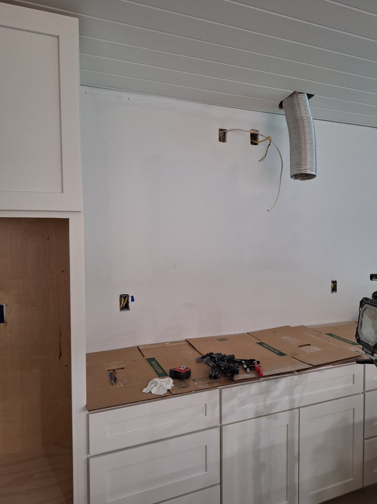
To my surprise, the extra cabinet that will go above the cooktop and the refrigerator side panel arrived early. I expected it to arrive mid month, but instead it arrived the first of April. So, my plan to install the overhead lights in the kitchen were put on hold. To prepare for the continuation of the cabinet installation along the east wall (the white cabinets), I had to go backward a bit. Having learned a few things while installing the kick lighting, I realized that I had to move the wire I had put in place for the under counter (U/C) lighting. I placed it so that it would emerge from just under one of the wall cabinets, thinking I would hard wire it to the U/C lights. Now that I know that the U/C lights will be controlled by a controller and power adapter, what I needed was an outlet (no hard wiring). Also, I wanted that outlet to be out of sight and not be a nuisance. So I decided to place it in the 12″ cabinet that will be high above the cooktop. Also, the outlet I had put in place for the vent fan would also be located in that cabinet, but it was a bit too low on the wall, so it had to be moved as well. So the first order of business was to take down the wall cabinet I already put up and start cutting into the drywall so the wires could be moved. Here was what I started with.

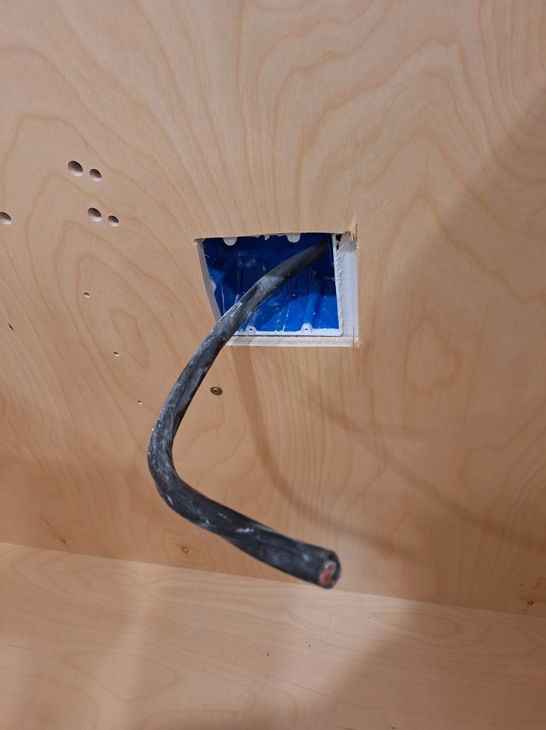
And here is the state of things once I opened up the wall.
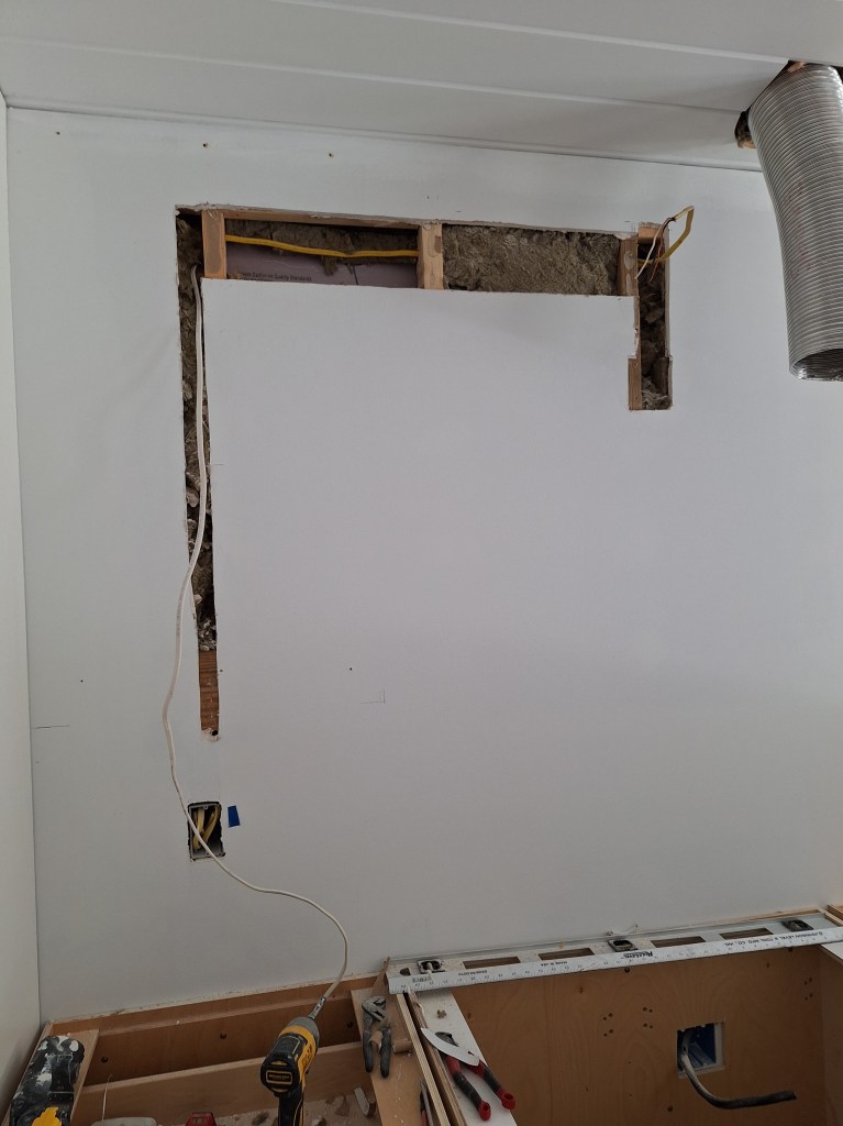
The white wire you see hanging down is for the U/C lighting. To move it to where I wanted it, I had to drill a couple of holes in the framing to feed it through. The yellow wire is for the cooktop vent, which just needed to be moved up a bit higher.

With the wires in place, I replaced the insulation, patched the drywall, then taped it.
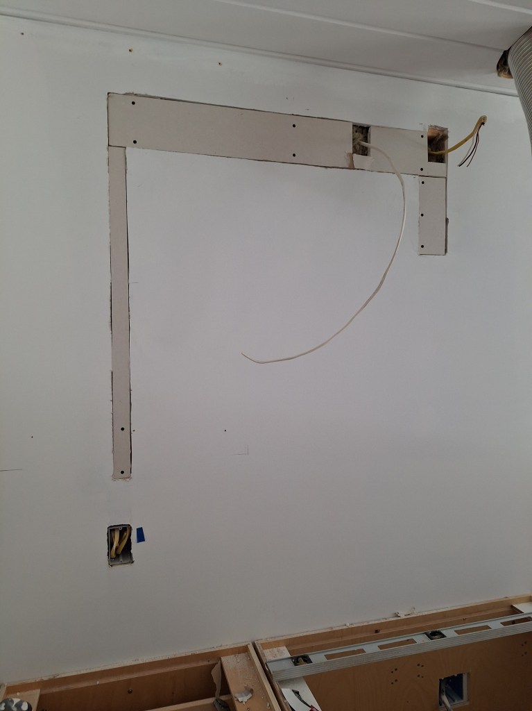
Since this area will be covered with cabinets and tile for the backsplash, the drywall patches do not need to be robust. The long vertical strip has only two screws holding it in place at the bottom. The drywall tape and mud will be all that will secure it beyond that. I really didn’t need to add this strip because it will be behind a cabinet, but I added it anyway.
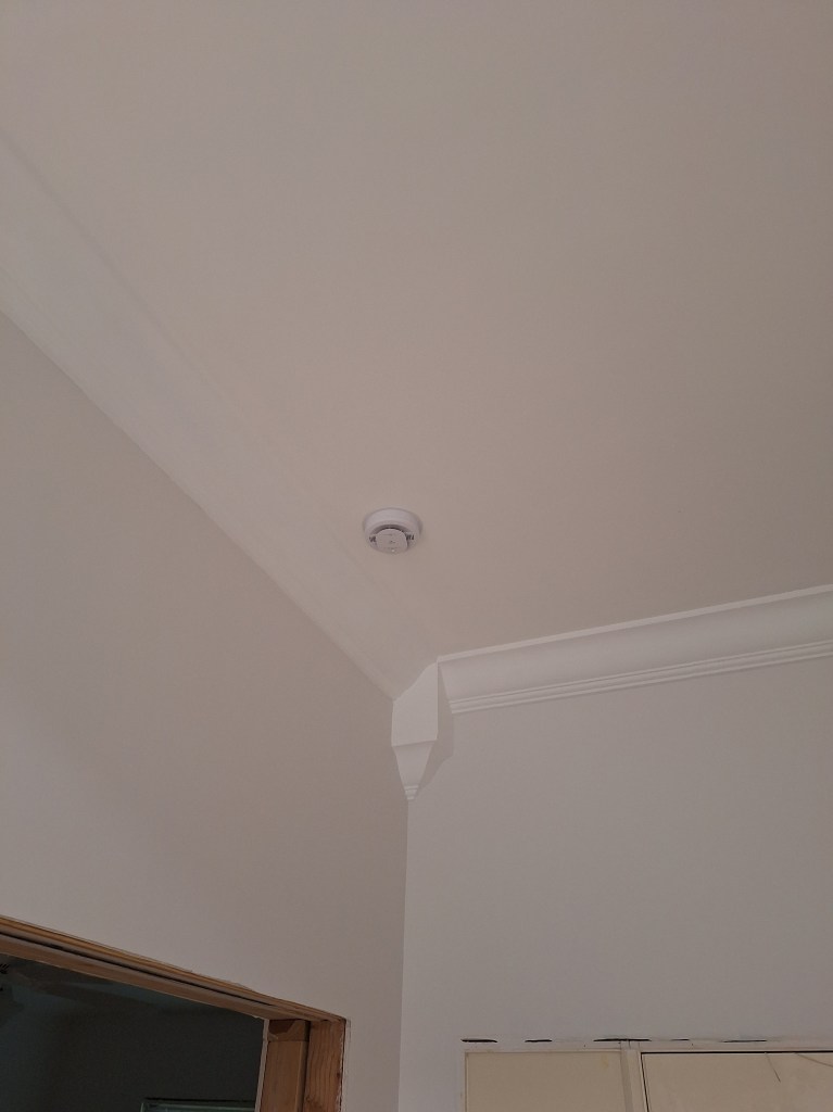
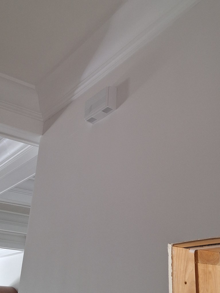
While waiting for the tape to dry, I installed all my smoke/CO detectors; seven in all. Here is the one in the foyer.
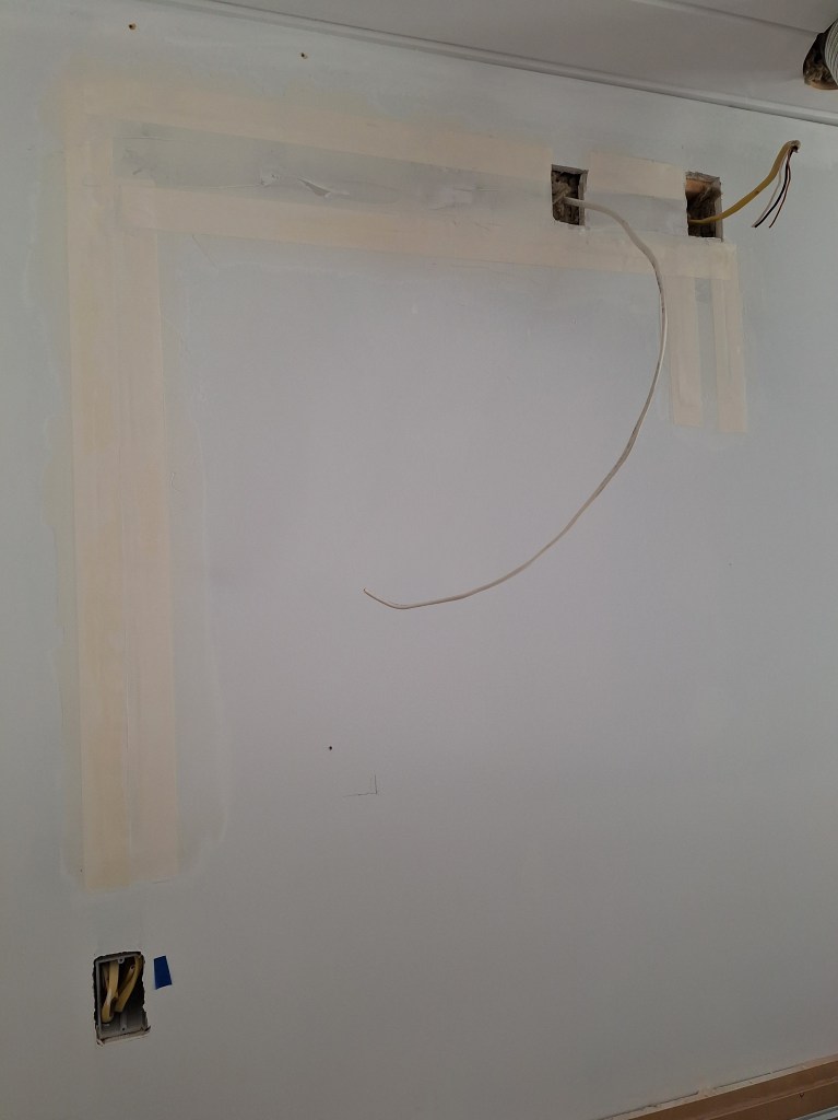
It was nice to get that job out of the way while the drywall tape was setting. Once the tape was dry, I added a single cover coat to it then added a coat of primer. This area does not need to look perfect, it just needs to be reasonably flat, so that was enough. The two openings at the top provide enough space for the junction boxes to fit into as I insert them through the cabinet back.
While the primer was drying on the drywall patch, I got to work modifying the opening of the wall oven cabinet. In the image above you can see part of the result. To get it there, I had to cut away 4 1/2″ from the top, then attach 11/16″ strips on either side to create the opening required, shown below.

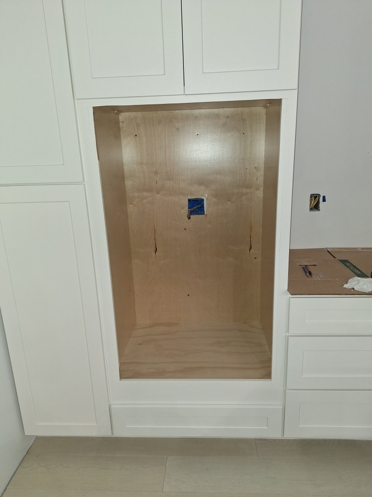
The oven I’ve purchased is a wall oven/microwave combo, so it is pretty big. It will fit into this space and overlap the perimeter by about 1/2″. It will also protrude a bit, making it align with the cabinet doors.
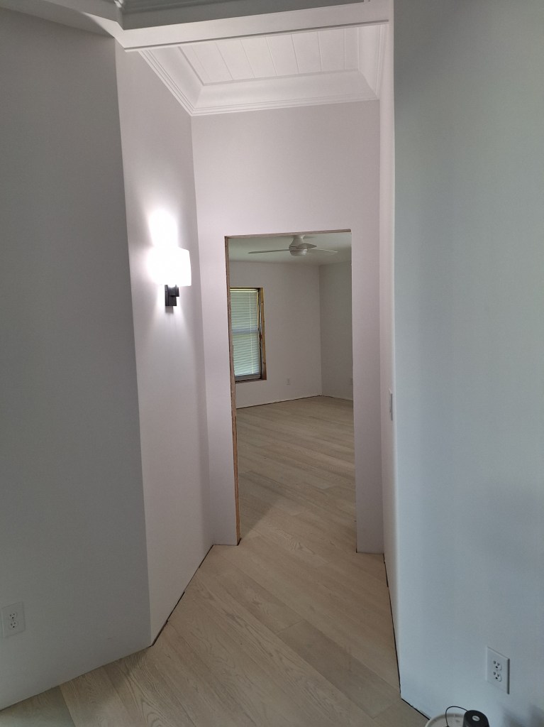
While waiting for the wall oven and vent fan, I purchased a couple of wall sconces. I will ultimately need four, but I bought two to see if I liked them. After receiving them I felt they were a bit too small for the foyer, but I liked them for the guest hallway and for the entrance to the master bedroom. I installed the first one in the guest hallway.
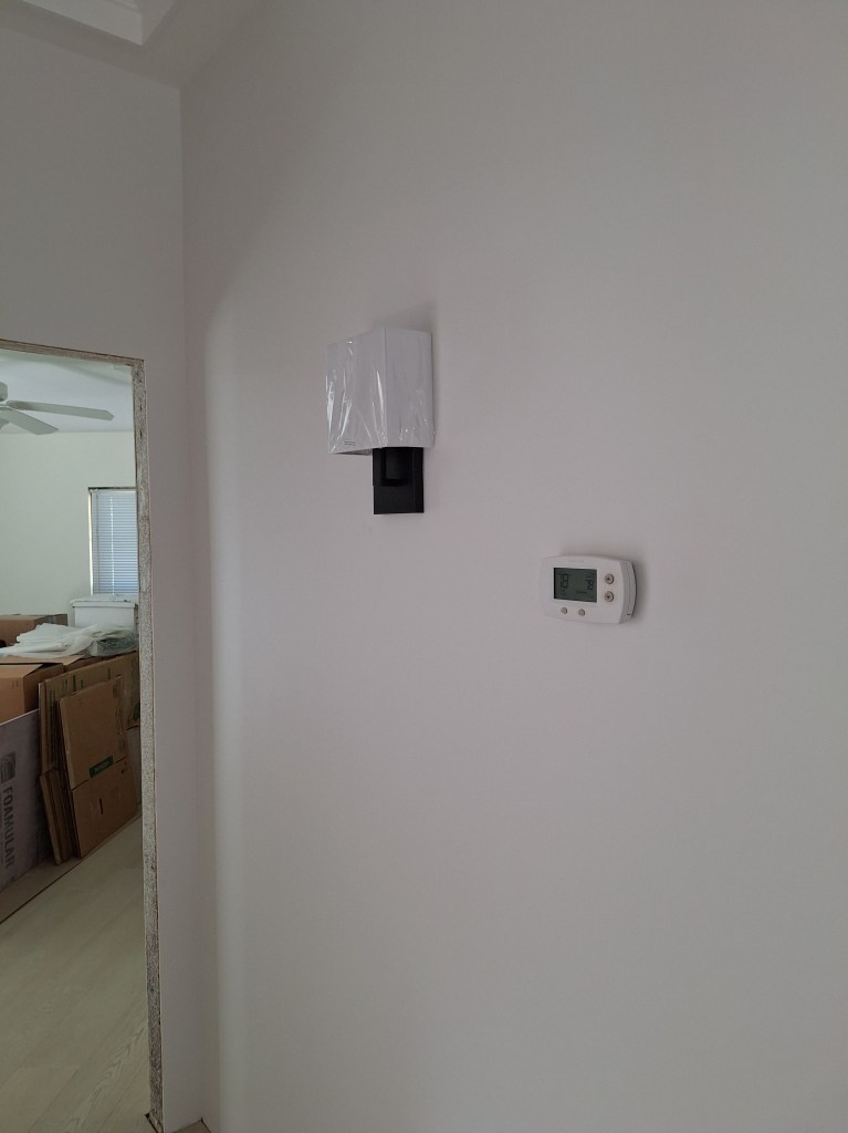
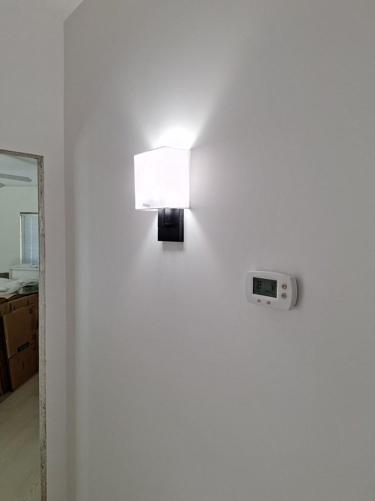
I think it looks good and the size is just right. I left the cellophane on the shade for now. I’ll take it off once I’m living in the house. No need to expose the fabric to dust before then.
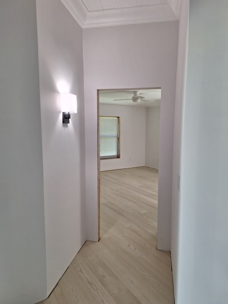
This was a pretty easy installation, so I was expecting the same for the sconce that would go on the wall just before you enter the master bedroom. Unfortunately, I discovered a wiring problem. The switch that controls the sconce was drawing power from the neighboring switch that controls the lights in the great room, which was a 3-way switch (there are actually four different switches that can turn on the lights in the great room). That would have been fine if that switch had been the first in the chain, but it was not. This meant that it would only supply power when that switch was on, lighting the great room. When I initially installed the switch for the sconce, I tested it, and it worked. What must have happened was that I tested it while the great room lights were on, not realizing that it was due to the great room lights being on that the sconce switch seemed to be working.
I had visions of having to open the wall and run a separate power line down to the switch when it occurred to me that I could tap into a power source in the attic and feed it down the existing 12/2 wire to the switch. I could use the black wire as the power to the switch then use the white wire as the output from the switch and connect it to the black wire in a junction box I would add to feed the sconce. Normally the white wire is for neutral, so reassigning it this way requires that I mark it with black tape, both at the switch and in the junction box to make it clear that it can be “hot”. This worked. I actually had to introduce a second junction box to extend the wire in the attic I was tapping into because there was not enough slack in it to reach the junction box connecting to the sconce.

After that I installed the doorbell. I learned something while doing this. In the garage there is a thing above the hot water heater.
I never knew what this was until I was up in the attic to find the wires for the doorbell. I knew where to find them because I marked them when I removed the doorbell. At that time, I simply cut the wires and labelled them “doorbell”. When it came time to reinstall the doorbell, I had to pay attention to where to connect the wires on the small circuit board that controlled the triggering mechanism of the doorbell. One was connected to a small screw labelled “transformer” and the other to a screw labelled “front door”. There was another for “back door”, but I had no need for that one. One of the wires in the attic lead to the front of the house in the direction of the doorbell button, so that wire was the one to connect to the “front door” screw. The other wire, however, went in the direction of the garage. It was then that I realized that it lead to that thing above the hot water heater, and that it was a transformer. Mystery solved! So I was happy to learn that. I connected it all up and pressed the doorbell. I was pleased to hear it ring.
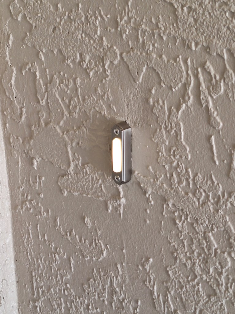
Before putting the cover over the doorbell mechanism, I spray painted it white to freshen it up. It was beginning to yellow a bit, so now it looks brand. I also decided to replace the doorbell button outside. Although the original button still worked, it had a bit of a crack in it and was showing its age. The one I replaced it with was a bit fancier, but still simple. It is illuminated by an LED light, so there will be no difficulty finding it at night.
Being pleased with my choice of sconce for the guest hallway and entrance to master, I ordered two additional sconces for the foyer, sticking with the matte black theme, but taller. They arrived after the doorbell was sorted out. Here is what I got.


I think they look great. Eventually I will hang a mirror between them, but I haven’t chosen one yet. That’s something that can wait. In the first image of the sconces above, if you look at the floor, you’ll notice I installed a door stop. This was needed so that the front door did not hit the sconce nearest it. You can get a better sense of this from the image below.
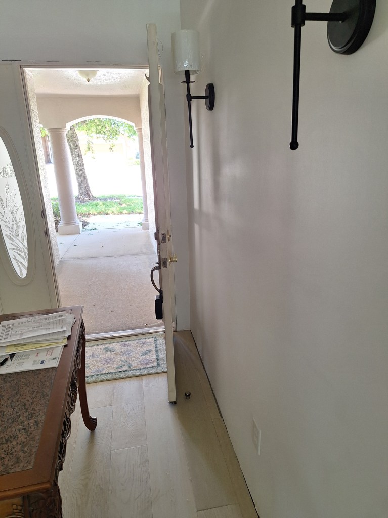
When the door is against the stop, it is just shy of the sconce shade. I couldn’t get the door to stay right against the stop when I took this picture, so you’ll have to use your imagination.
With nothing left to justify putting off the installation of the overhead lights in the kitchen, I reluctantly, I turned my attention to that. I was reluctant because I was not looking forward to using the hole saw to cut into the tongue and groove ceiling.

I would be using the same 6-3/8″ hole saw I used in the great room, shown above. When creating the holes in the great room, I remember it being quite challenging. You are working over your head with something that has a tendency to kick out if you’re not careful. After finishing the last hole in the great room ceiling, I was very relieved. And now I had to do it again, but this time it would be even more challenging because the tongue and groove ceiling is thicker than the tongue and groove in the coffers of the great room.
I originally planned to put in eight 4″ recessed lights, thinking 4″ would be sufficient. I started with the smaller hole saw, but stopped when I felt it was too dangerous. I resorted to using a jigsaw, which wasn’t much better. It certainly made a much rougher hole. I installed the 4″ light and then realized it was too small and, more importantly, I needed to install gimbal lights so I could adjust the direction of the beam to account for the sloped ceiling. Odd that I didn’t think of that ahead of time. So I ordered new lights. They arrived, and I didn’t like them. So I returned them and got on with other tasks (the things I described above). As those tasks were winding down and knowing I had to face this one, I found the lights I thought I would be suitable – 6″ and gimballed.
It was time to face the dreaded hole saw, but this time I decided to add the auxiliary handle that comes with my drill so that I could get a firm grip on it (shown attached to the drill in the image above). This made all the difference. The drill was stable and I was able to hold it securely the entire time. There were no kick back issues. This is where my lack of experience shows. I wish I had thought of this while drilling out the holes for the lights in the great room ceiling. It was still a messy job with saw dust falling in my face the entire time, but I was masked up, goggled up, and wore a hat, so it wasn’t that bad. More importantly, the holes were nice and tidy.

Below are a series of images after the installation of all eight lights.
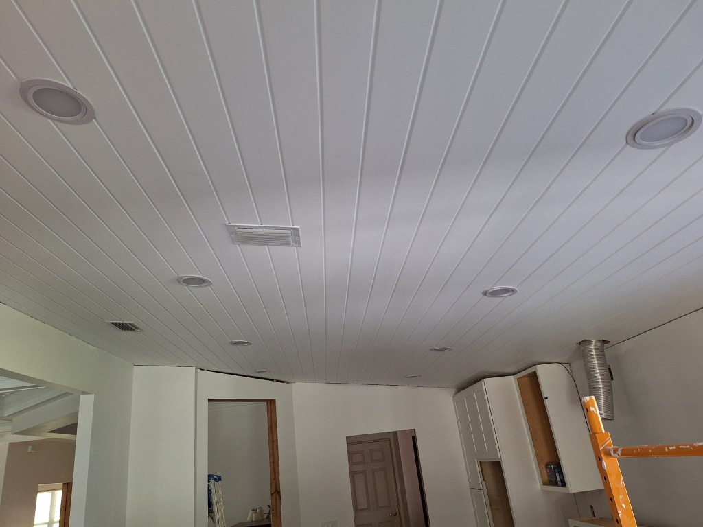
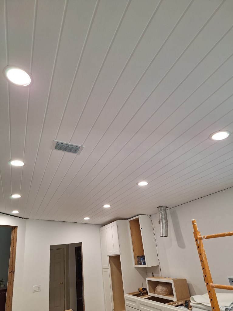

I was both pleased and relieved to have this job done. I’m happy with the result, and it’s nice to have light in the kitchen again. Although these lights are dimmable, I did not see the need for a dimmer switch, since it is a workspace. That can always be changed if I find a need for it.
The next day my wall oven/microwave unit was to be installed and the vent hood for the cooktop would arrive. The installers got to work installing the wall oven/microwave, but when they powered it up, only the oven turned on. In the end, they removed it and took it back to figure out what went wrong.
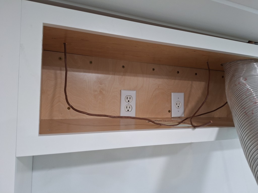
While that was going on, I started preparing the 12″ cabinet that will go above the cooktop and will support the vent hood. This meant that I needed to cut several holes in the cabinet: one on top for the vent pipe; two on the bottom for the exhaust of the vent fan itself and an opening to feed the plug through; two holes in the back for outlets (one for the vent fan and the other for the under counter lighting); and finally, I needed two small holes on the top to feed the under counter wire for the two wall cabinets on either side. It also required that I add two 3/4″ solid wood strips at either end so the vent hood had something substantial to screw into.
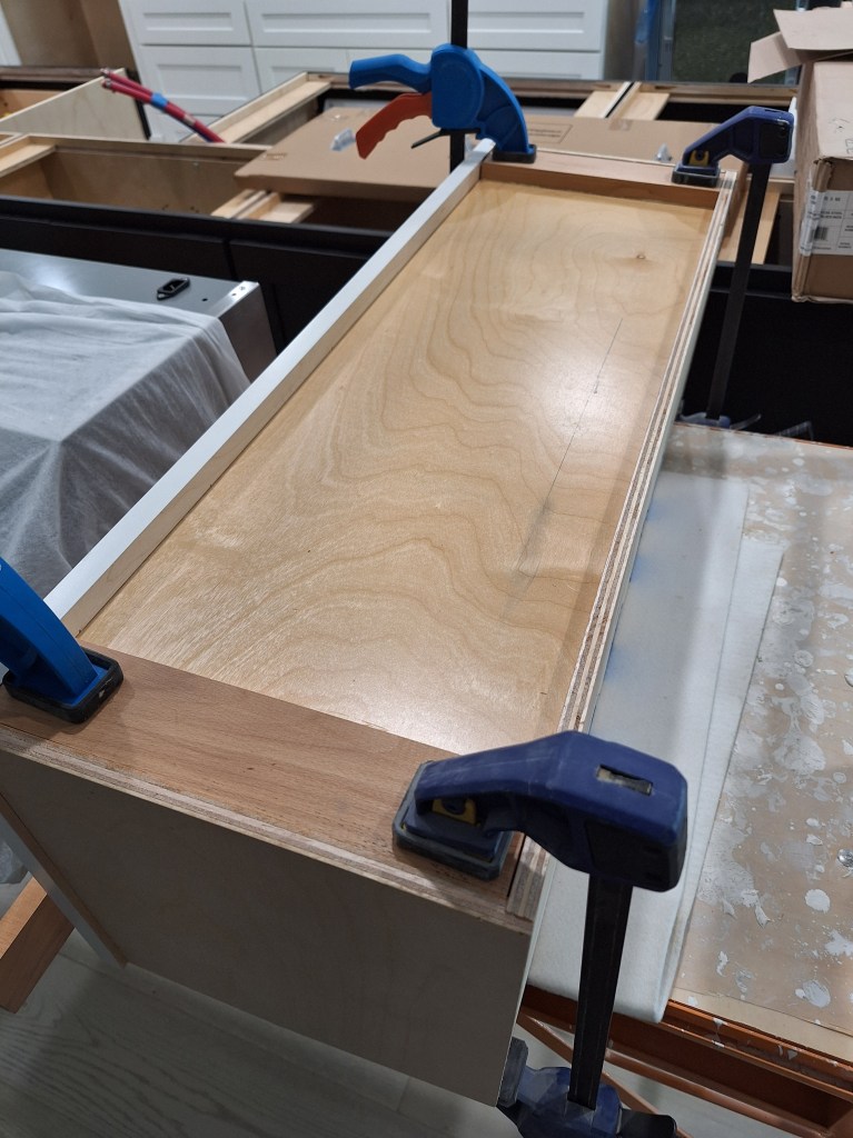
With all that done, I was ready to lift it into position.

To assist with this, I screwed a ledger board to the wall so I had something to rest the cabinet on while I fiddled with the exhaust pipe and alignment. With it in position, I used the two clamps you see to hold it where I wanted it before fastening it to the wall with screws. I then added junction boxes, wired the two outlets, and screwed the face frame to the face frame of the adjoining cabinet.
Because this cabinet will be supporting the vent hood, which is not light, I added extra screws to ensure the cabinet is well secured to the wall.

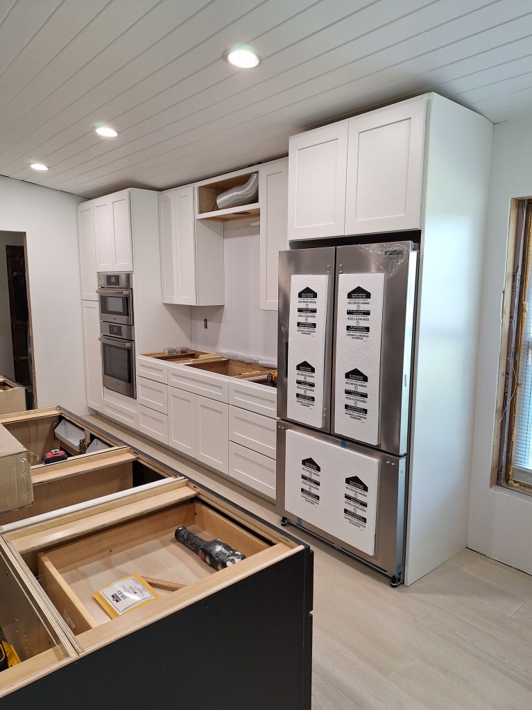
Next to this cabinet I installed the other tall wall cabinet, followed by the first of two refrigerator panels.
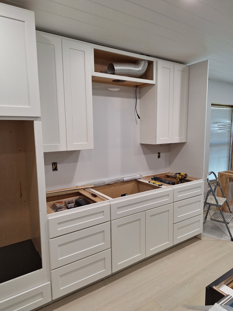
From the above image, you can finally get a sense of the workspace around which the cooktop will be centered. To complete the cabinets along this wall, I have to add one more cabinet that will go above the refrigerator and the second refrigerator panel. To help with the installation of the cabinet, I pulled out my lazer to decide where to place the ledger board that would support it during the installation.
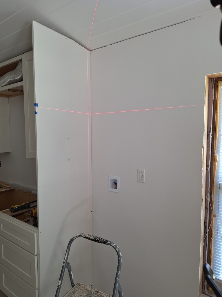
The two blue tape marks on the refrigerator panel identify where the top of the refrigerator will be and where the bottom of the cabinet will be. So there is a bit of space between them, as I’d expected. I just wanted to be sure before I started installing the cabinet. I stopped work on this for the day as my wall oven/microwave combo appliance was delivered and installed. Here it is:
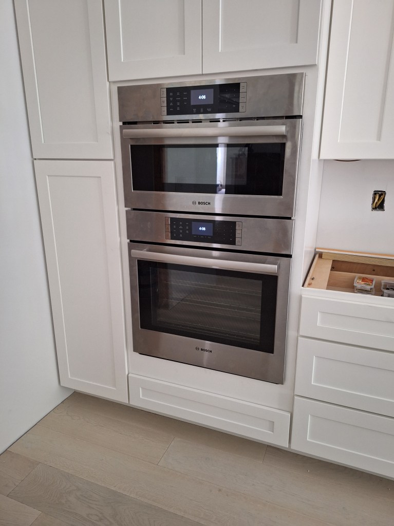
It fit nicely, and is the first appliance to be installed in the kitchen, so a seminal moment.
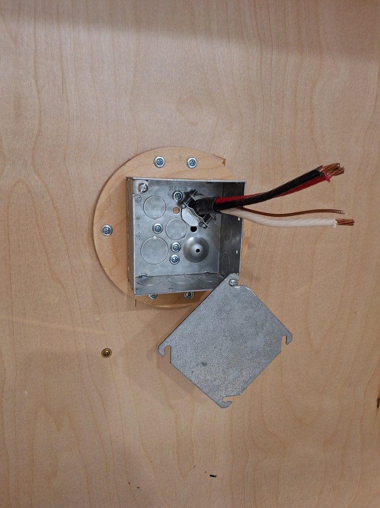
Here is a bit of the back story regarding the failed first attempt at installing the wall oven. When the installers arrived for the first time, they were expecting a different setup. What I provided was something like what you see below. I did not take a picture of the junction box in the wall oven cabinet, but it was identical to what I did in the cabinet for the cooktop, so what you see below is representative of what they found when they arrived.
The installers were expecting a metal junction box that would be surface mounted and have knockouts into which the whips (metal cased wires connected to the appliances) could be secured. Without that, they chose to simply connect the whips to the cable that extended out of the wall and leave them dangling behind the unit. Although not pretty, that should have worked. But it didn’t, so they took the appliances back to test at the store. They worked when hooked up at the store, so they sent a different fellow out to ensure my wiring was correct. It was. During that visit, I talked to him about installing a surface mounted junction box. Having witnessed the first installation attempt, I knew I had room to accommodate it, and he thought it was a good idea. So in a way, that failure was a blessing. It gave me knowledge of what was expected and the time to make the adjustment. So, making use of the off-cut from when I cut the opening for the cooktop exhaust vent, this is what I added.
The second attempt to install the oven/microwave was successful. The person who installed it this time was the same guy who came out to check on my electrical setup. I got the impression that he was the main installer. He figured that the reason the first attempt failed was due to the wires not being stripped back enough to make a good connection (not the absence of the junction box shown above). But the presence of the junction box made for a much tidier and secure job.
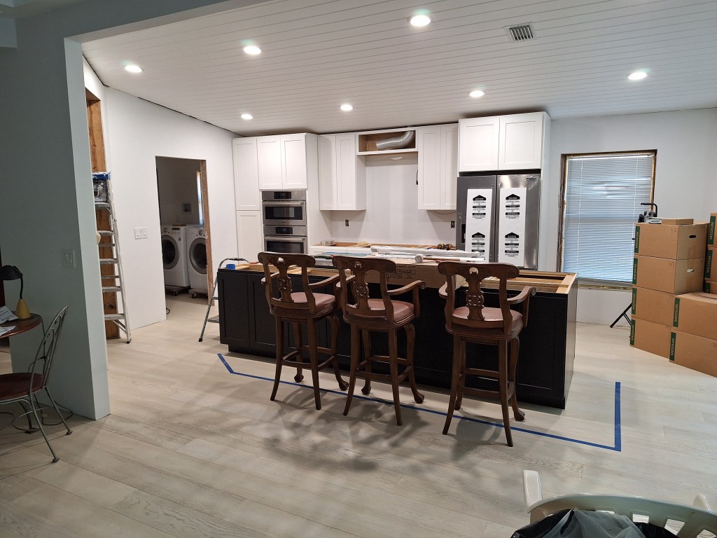
The next day I got back to installing the remaining cabinet and refrigerator panel. I got some help from my friend and neighbor, Fred, who helped lift the cabinet onto the ledger board and hold it in place while I aligned it and secured it. After that I had just the second refrigerator panel to do. Since it was the end piece on this wall, the cut I made at the top to accommodate the sloped ceiling would be visible and therefore had to be clean, and it was. Here is a shot of the entire cabinetry along the east wall.
Note that I pushed the refrigerator into position, but it is not yet hooked up. I just wanted to see how it looked, and I’m happy with it. I’ll leave the protective Styrofoam on until the installation is completed. I’ve left the doors off the cabinet above the cooktop because I have some work to do there to get the venting for the cooktop exhaust fan sorted out. Here are a couple more shots.

With the cabinets installed, my focus turned to the cooktop exhaust venting. I was recently told that one is supposed to use rigid pipe with a smooth interior when venting the exhaust. I looked it up and that appears to be true. Oddly, the flexible pipe I installed long ago has been visible every time the inspectors came by, and they never pointed that out, so I’m not sure if this is a hard and fast rule. I won’t be able to replace the section that is above the cabinet and extends to the roof, but I would like to bring the pipe that is within the cabinet into compliance. I spent some time looking for a solution using off the shelf parts, but it is such a tight space that nothing would fit. So I think I am going to look for a fabricator to provide me with a custom solution. I’ll report on that in the next post.
Following from my experience with the wall oven installation, I decided to follow suit and add a surface mounted junction box for the cooktop. Again, I made use of some off-cuts to serve as a mounting surface, securing the junction box to it before attaching the mounting surface to the back of the cabinet.
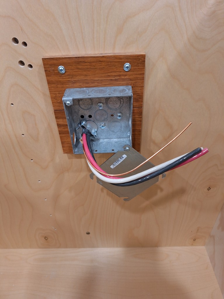
The whip from the cooktop will secure to the right side of the junction box and, once the wires are connected, will tuck away nicely within it and be covered by the plate you see hanging down.
I will be taking a week off to visit family and friends. When I return I will start by addressing the exhaust vent ducting for the cooktop. Here endeth the post.
