With the network cables patched in to the rack, the remaining networking tasks include adding a switch, router, modem, and battery backup. But I do not intend to get to that until I am ready to start using them, which won’t happen until we are approaching move-in time. My focus at the moment is to address the things that need to be done while the walls are open. So next up is electrical work; specifically, hooking up switches and outlets.
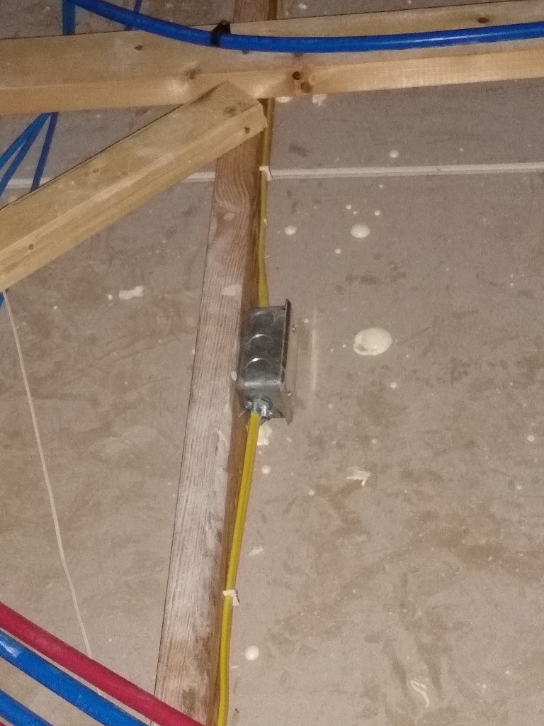
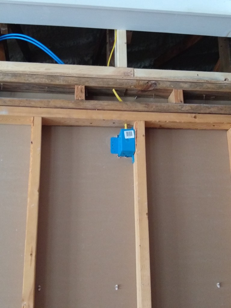
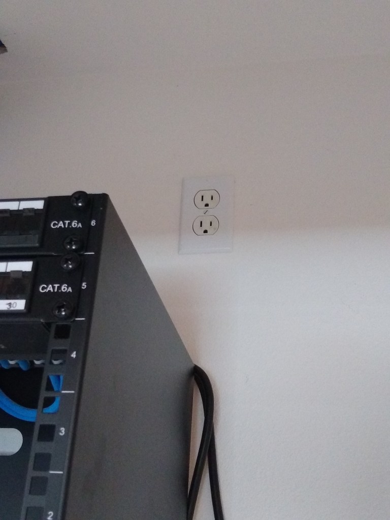
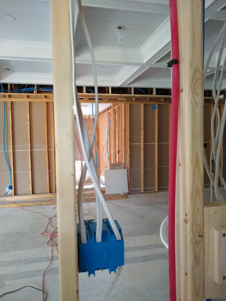
The first job was to add an outlet above the network rack so that the power distribution unit has some place to draw its power. This was not a difficult task, but did require I add a junction box in the attic so I could extend a spare wire I placed up there (just in case!). I needed another 25 feet of wire to reach the network closet. The following pictures, from left to right, show the junction box in the attic, the box it connects to, and the other side of that box (the outlet) above the rack.
The next priority was to wire the switches in the kitchen. But before getting to that, I needed to shift a large amount of debris I had been storing in the garage so I could get access to the breaker panel.
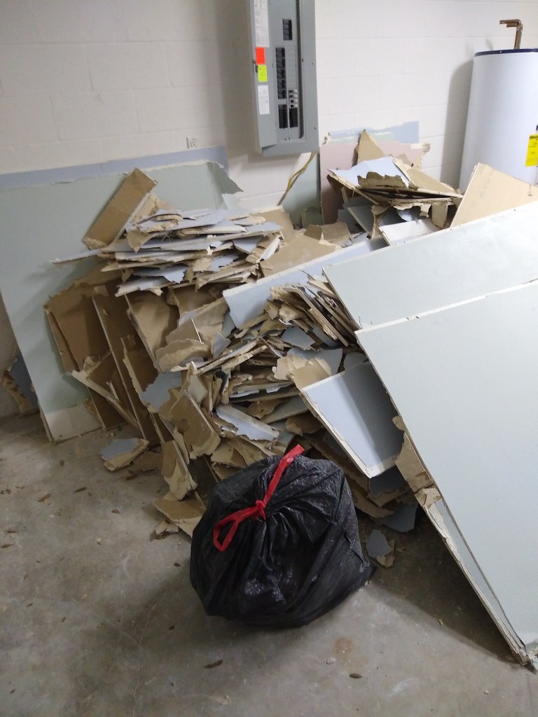
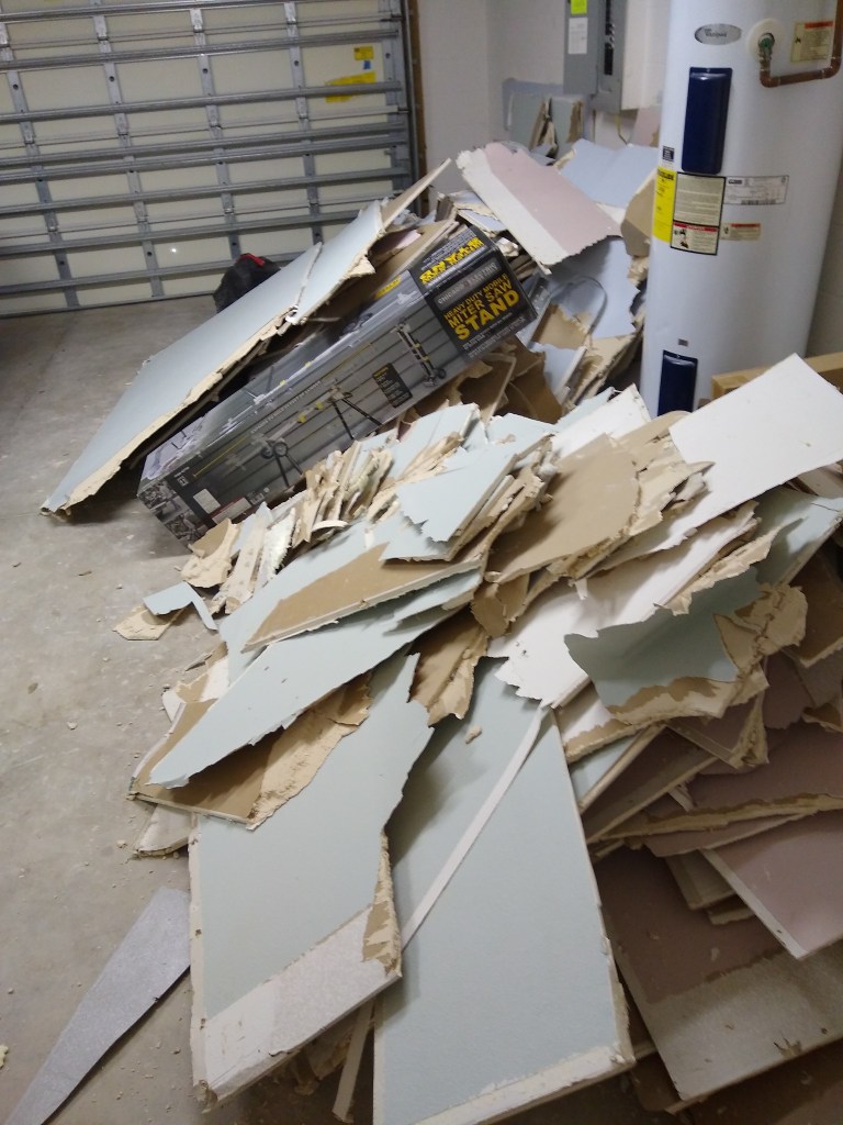
Before calling the hauling/disposal company to collect the debris, I needed to demo the remaining drywall I planned to remove so that it would all be hauled away in one trip. So I took a day to remove the rest of the drywall from the dining room.


The hauling company arrived the next day and removed the junk from the garage. Much better!

With that out of the way, I could get to work on the kitchen switches. I planned out what I wanted a long time ago, so I ran the wires before the kitchen ceiling went up. There will be two boxes to control the lights in the kitchen. One box will be a 4-gang that will be on the wall above the dishwasher. The first of the 4 will have a dimmer switch for the light above the island. Next to it will be a switch for the can lights in the ceiling. Next to it will be a switch for the under-counter lights, followed by a switch for the kick plate lights. I originally planned (and actually wired) dimmer switches for all 4 switches, but later changed my mind, thinking it was overkill. It was pretty unlikely that I would be dimming the lights other than the one above the island. Consequently, they were replaced with non-dimmable switches. I can always replace the switches with dimmers someday, if I fancy it.

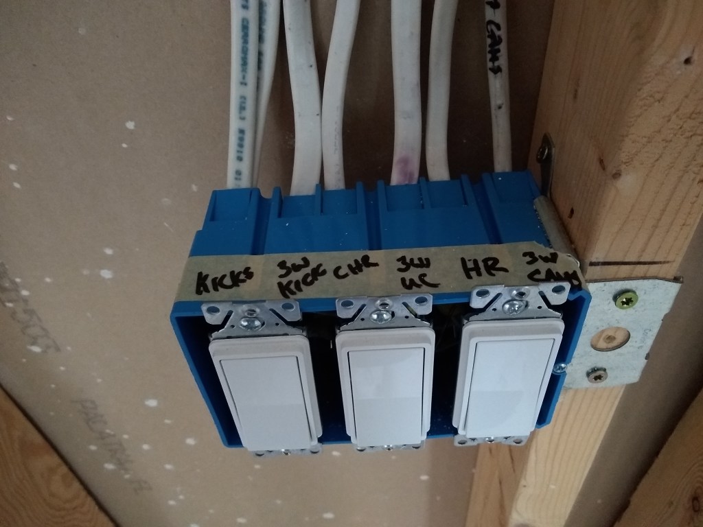
The can lights, under-counter lights, and kick lighting are also controlled by another set of switches so that you can control these lights when you enter from the garage. This required a 3-gang box on the wall next to the laundry room.

Next it was time to wire the switches. Here is the result.
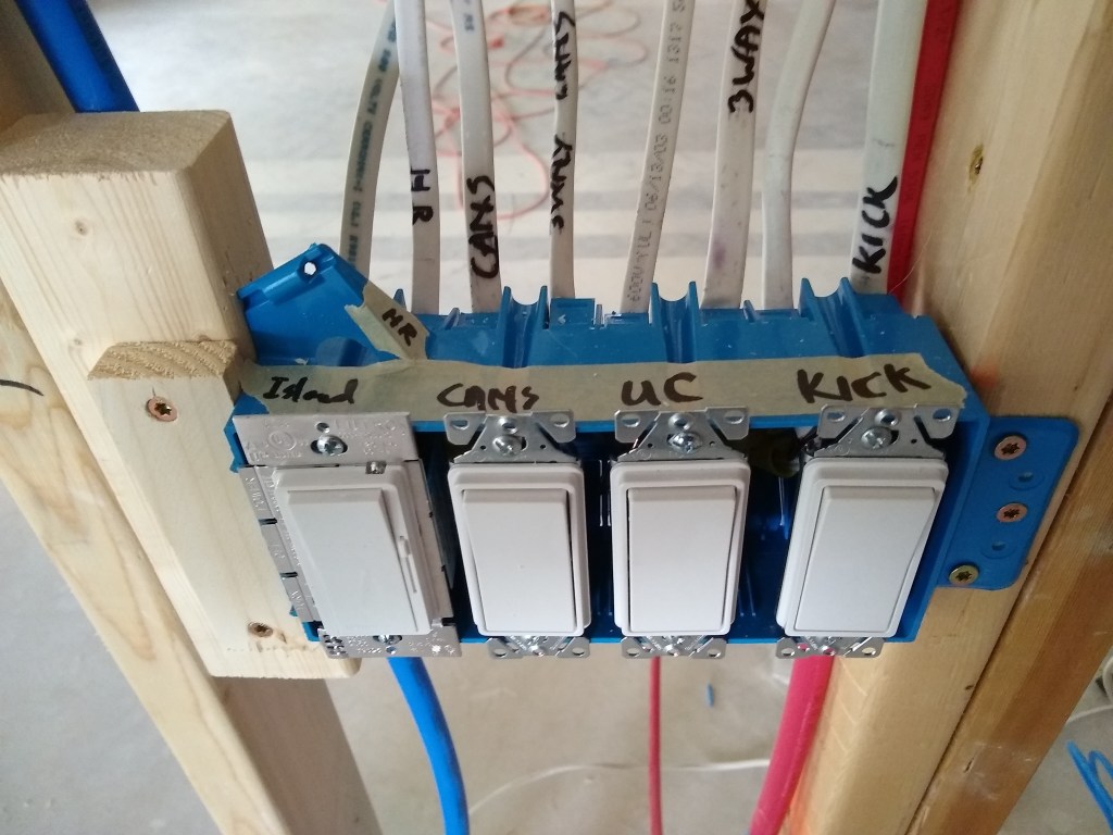
Of course, the other ends (lights) are not hooked up and won’t be for some time. This task was to simply get the switches in place and tested. They were already connected to the breaker, so I was able to test them using a small handheld tool that lets me know when the line is hot.

With this little tool, I was able to test the output of each switch. For the 3-way switches (cans, under-counter, and kick) I would go back and forth between the each pair of switches to verify that when one turned on the light, the other could turn it off (and vice versa).
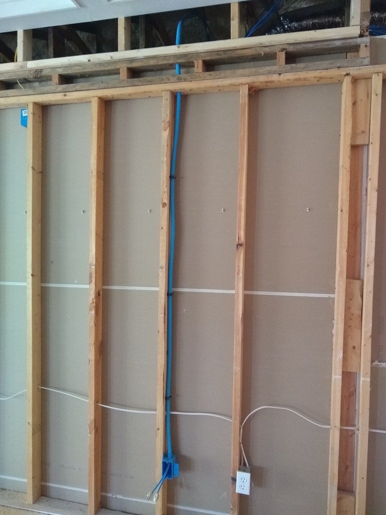
The next day I tackled the wiring for the fan in the great room and the sconce that will be placed on the wall of the entrance to the master bedroom. Both required running wire above the ceiling and installing switches. The fan has just a simple switch, while the sconce gets a dimmer. Here are the results.

In the first image above, the fan switch is to the left of the switch for the coffer lights. The second image shows it from the back, and includes a shot of the other end of the wire if you look up at the ceiling. The third image is a closer shot of the wires the fan switch controls. As with the kitchen lights, the fan will not be installed until after the painting. Below the switch box you can see the wire that provides the power for the fan switch (only). I wanted this switch to be on a separate circuit from the one controlling the coffer lights, so I connected it into the circuit used for the outlets in the great room.
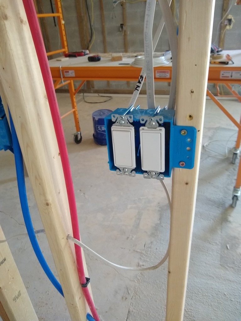
The following images show the setup for the sconce that will sit on the wall opposite the switch.


The dimmer on the left (above) is the one that controls the sconce. The dimmer next to it controls the coffer lights (installed quite a while ago). Both switches share a circuit, so the wiring was pretty simple. The right image shows the entry to the master, where the switches reside and, if you look closely, you can see the wire hanging down on the opposite wall where the sconce will be placed.
On the next trip up, I added dimmers for the sconce that will be in the hallway by the guest bath and a dimmer for the dining/piano room.


Following that, my trip up to the house was hampered by a major accident on I-95, which caused me to sit in traffic for a long time as all lanes were shut down. As such I only had a couple of hours to work, so I started adding clamps to secure the conduits used for the Ethernet cable. Not especially important, but it had to be done and made me feel like I had accomplished something before I headed home.
I still had a couple of wires that needed to be connected to the breaker panel. They had previously been fed into the panel, but I just left them dangling. I wasn’t sure how to do the hookup part, so I put it off until now. So, on the next trip, I planned to mess with the breaker panel.
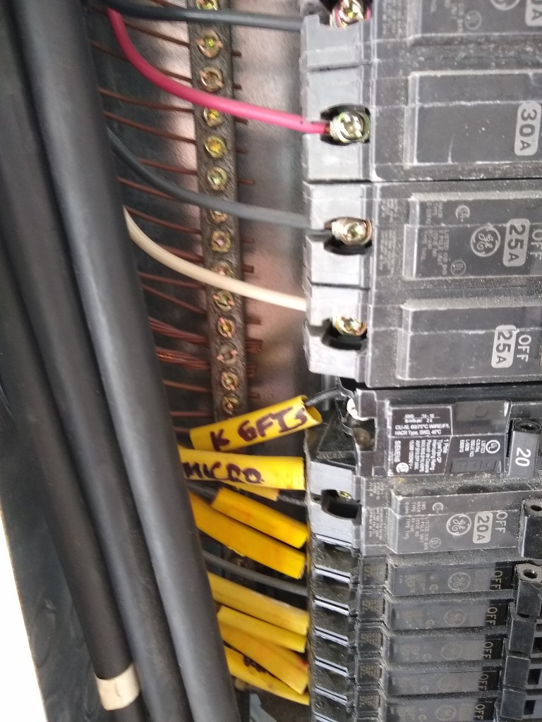
Before starting I spent some time making sure I knew what wires were controlled by each circuit. It turned out that I was confused about some of them, so it took some time to map them out and decide what wires would go to what breaker. Because of the reconfiguration of the kitchen, some wires were reassigned because of proximity. Consequently, I had to make sure that with these changes I had sufficient amperage where needed. For instance, the 20 Amp wire for the microwave is now used for the range hood, which only needs 15 Amps. In that case it was more than enough. Had the reverse been true, I would have had to rearrange a few things. I eventually got it sorted, but only had enough time to add one of the dangling lines to the breaker. I connected the wire for the network outlet to an existing spare 15 Amp breaker. That there was an extra breaker available, was nice.
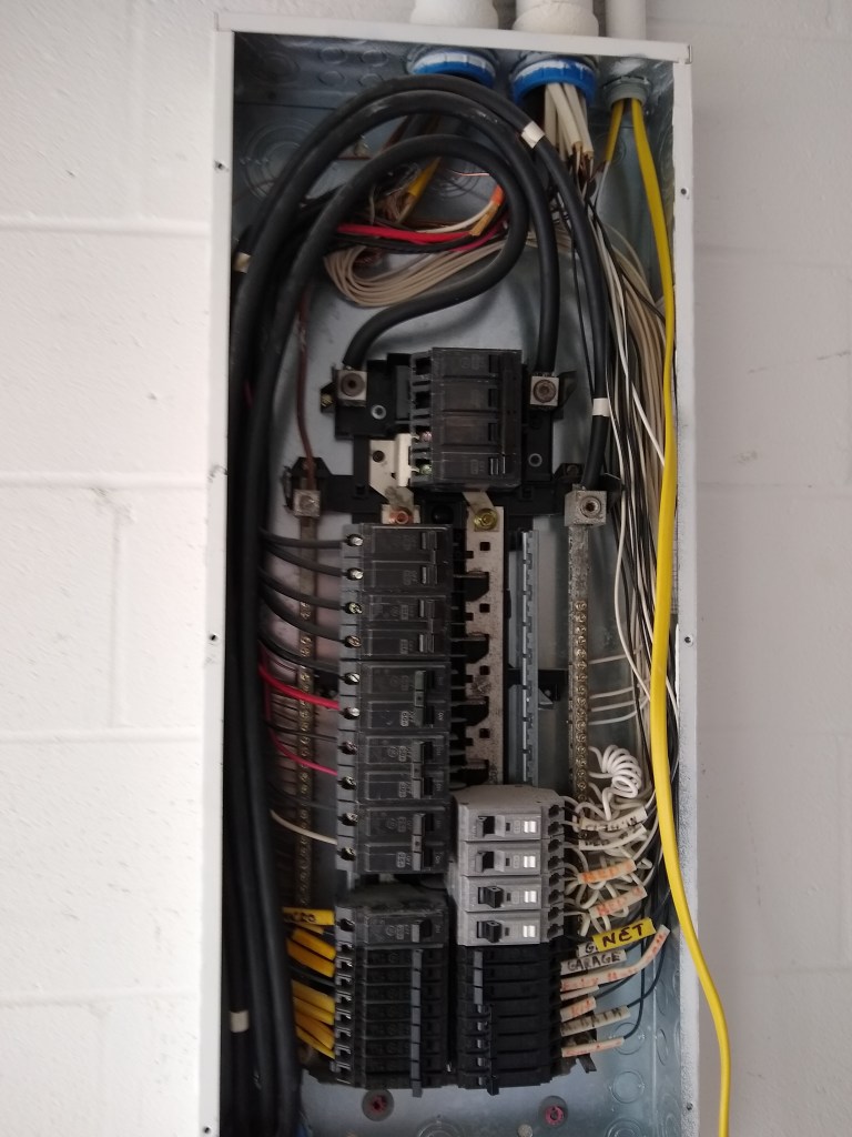
The panel is arranged so that 15 Amp circuits are on the right (even numbered slots), while the higher Amp circuits are on the left. Also, during the original wiring of the house, 14 guage wire (white sheathing) was used for the 15 Amp circuits, while 12 gauge wire (yellow sheathing) was used for the 20 Amp circuits. Back before the spray foam was applied to the attic space, I ran and extra wire. The spray foam application would seal off the conditioned part of the attic from the unconditioned part above the garage (where the panel resides). So this extra wire from the attic above the garage to the conditioned attic space was put in place as a contingency, so that I had the ability to add an extra circuit some day without disturbing the barrier between the conditioned and unconditioned spaces. The wire I ran was 12 guage (yellow) so that I could accommodate either a 15 or a 20 Amp circuit.
Although I didn’t intend it, I ended up using this extra wire sooner than expected. I employed it for the outlet used by the network rack (recall that the notion of adding a network rack came to me well after the spray foam work was completed). As a consequence of that, I deviated from the original convention and used a 12 guage wire on a 15 Amp breaker (heaven forbid!). That is why you see a yellow tag (NET) among a sea of white tags on the right side of the panel.
The extra yellow wire dangling in the panel will be used to connect to a new 20 Amp breaker that will fill the gap on the left side of the panel. This will be the circuit for most of the kitchen GFIs. Below I show the breaker panel after attaching the new breaker. Note that there is no more gap.
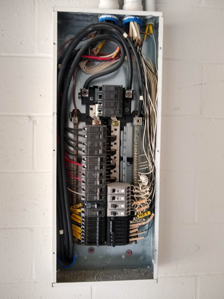

Of course, I tested these before putting the panel cover back in place. I don’t expect to have to mess with the break from this point on (fingers crossed).
After finishing with the breaker, I secured the wires from the 4-gang and 3-gang switch boxes, as shown below.

This does not end the electrical work, but is sufficient for this post. There will be odds and ends as I move forward, but I will only mention them if I feel it adds value. In the meantime I have started collecting estimates for new impact/hurricane resistant windows and doors. That will take some time (likely months) before they are ready to be installed (not by me!). While that is ongoing, I will start to explore the options available for sound insulating the interior walls. I would like to make the rooms as quiet as possible, and am curious to see what I can put between the studs to help with this before the drywall goes up. So that is where I am headed next.
