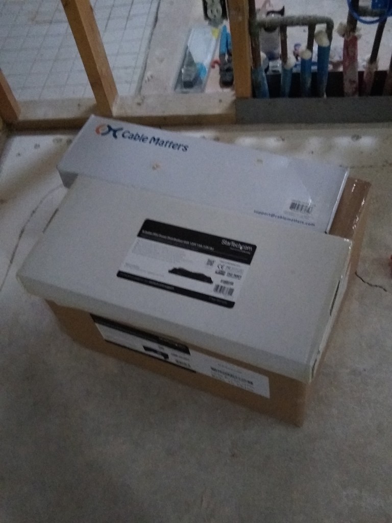
The additional cable and networking equipment arrived on time, so I was able to add the remaining runs and begin the process of terminating the cables.
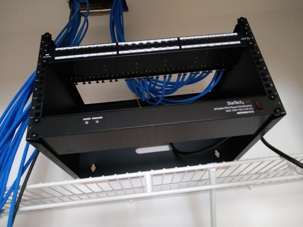
The first step was to mount the rack in the network closet.
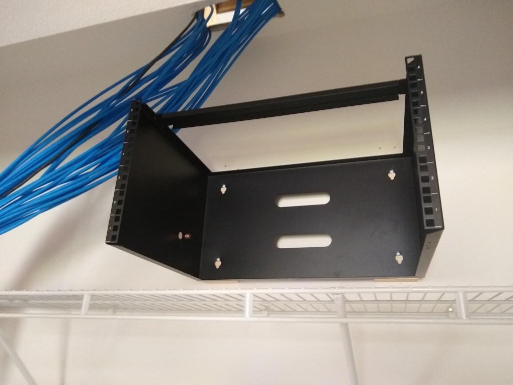
I mounted the power distribution unit/surge protector to the lowest slot (see below). That will plug into a power outlet I have yet to add and will provide 8 additional outlets for other equipment requiring power (i.e., router, modem, etc). I decided to divide the cabling into two sets based on the directions they ran above the ceiling. I have 30 cables in total and only 24 ports on the patch panel, so another patch panel would be needed. The lower patch panel would be used for the cables that ran toward the south of the house (right side of rack), and the second patch panel (on order) would receive the cables that ran toward the north (left side of rack).
Having never done this before, I took it slowly. I punched down one cable into the patch panel and terminated the other end with an RJ45 connector. Then it was time to pull out my new tester tool to verify that the connections were good. It passed! Time to do the next one.
Having gotten the hang of it, I proceeded to connect the remainder of the 16 southbound cables to the first patch panel.
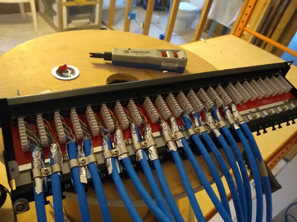
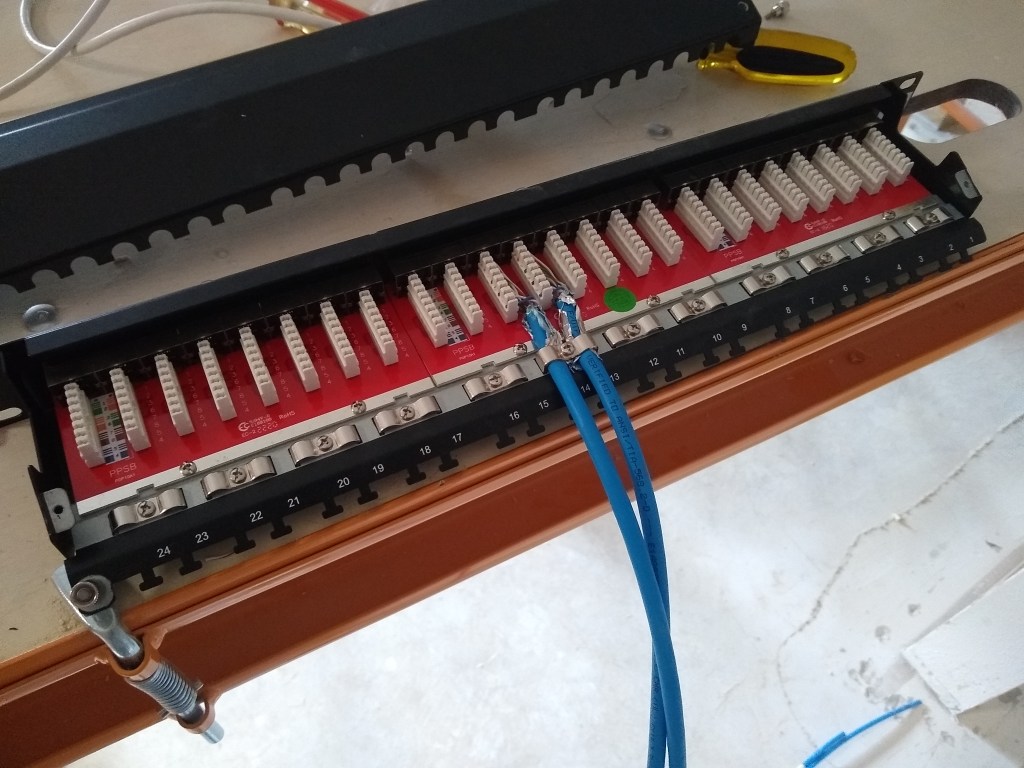
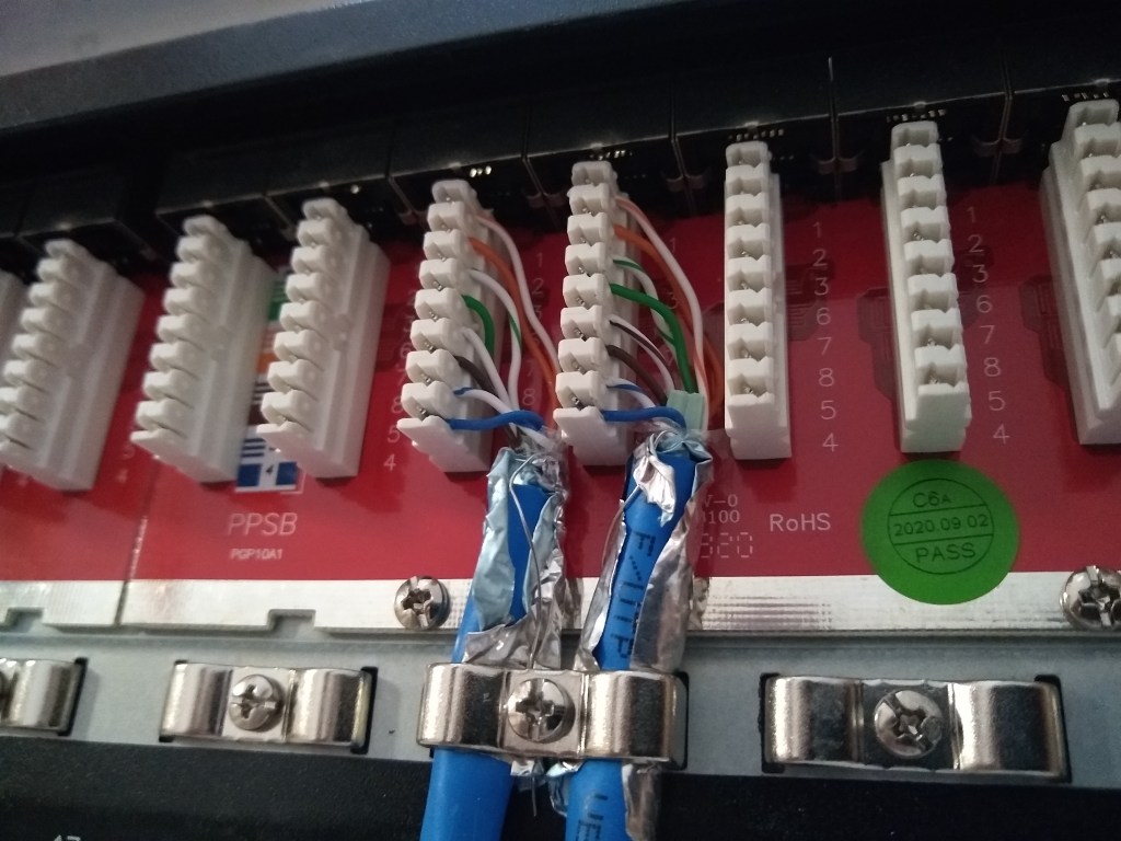
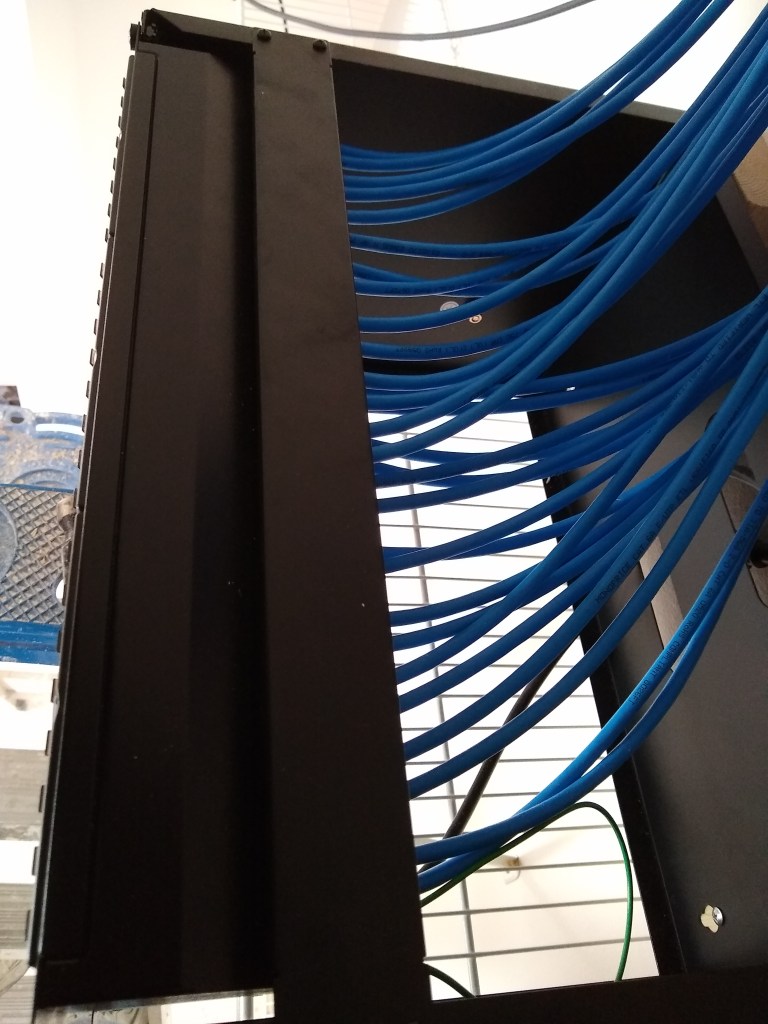
It is a kind of tedious task. The other ends were subsequently terminated and tested, so hopefully I will not have to mess with these connections again. In the second image above, you can see the punch down tool used to punch each wire (8 wires per cable) down into the appropriate slot of the connector. The cables are secured by metal brackets. There are also metal tabs to which you can add further support using plastic ties. Finally, a metal dust cover is placed over it all, which will make it look nice and tidy before placing the patch panel in the rack. And here it is:
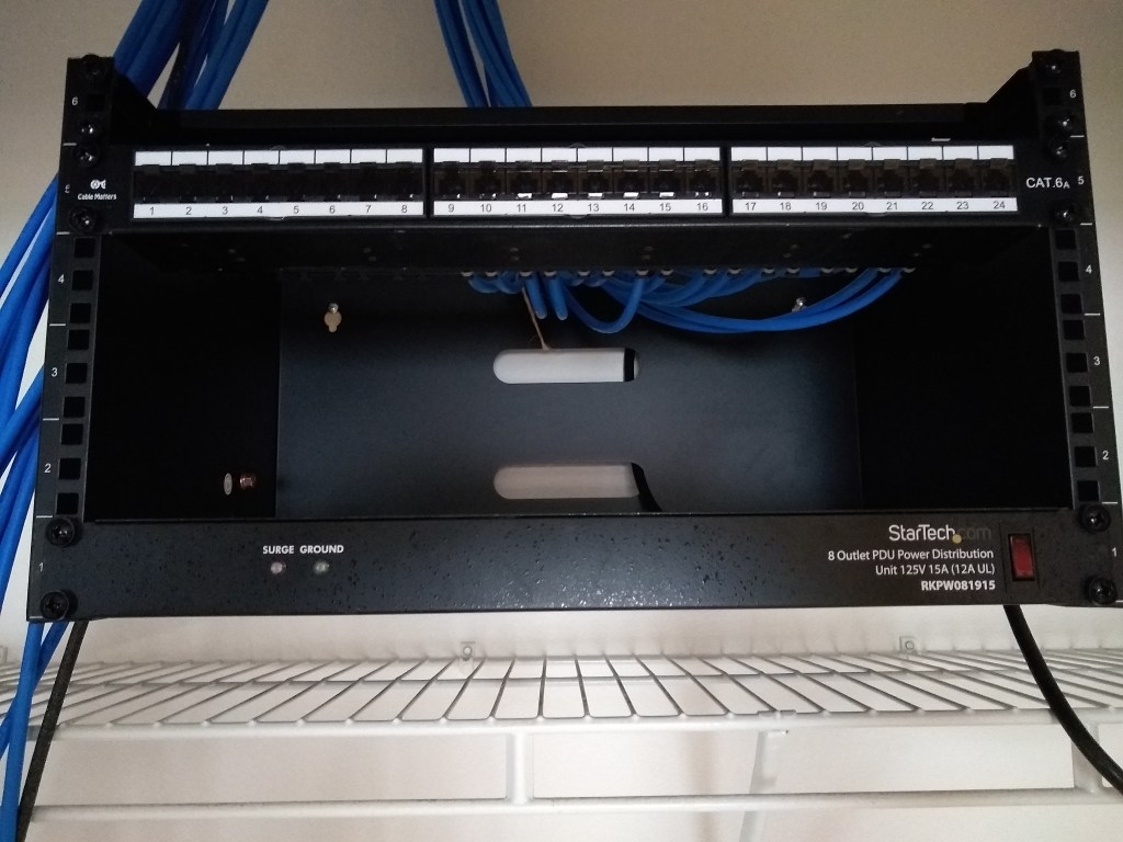
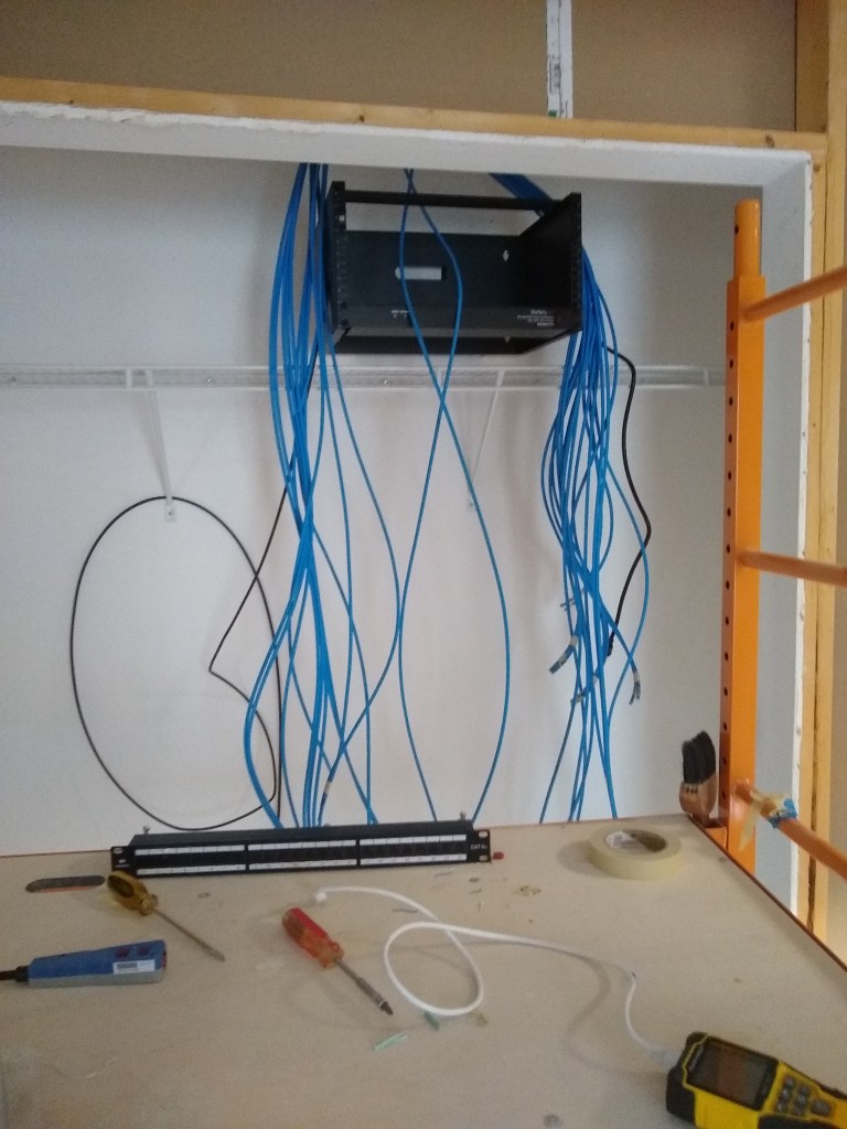
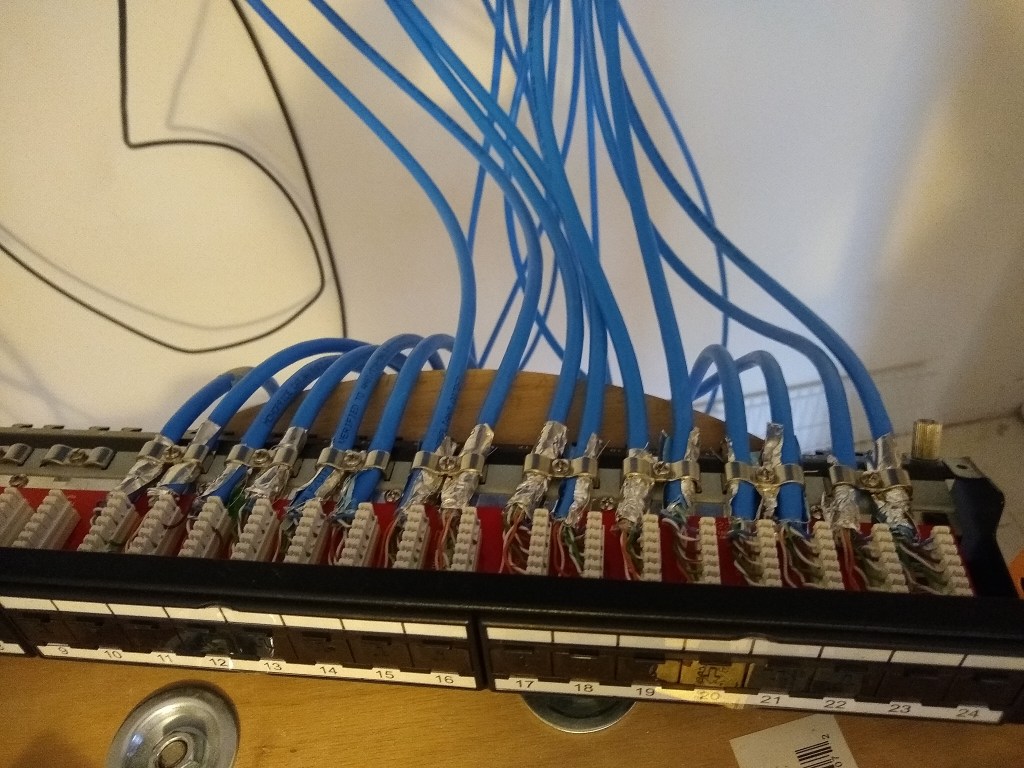
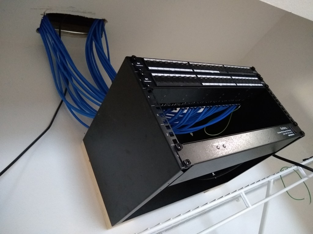
With the first patch panel mounted, it was time to get to work on the second one, which arrived while working on the first one. The first patch panel had 16 cables connected to it (the southbound lines), so the second patch panel that would be mounted above the first would have the remaining 14 cables (northbound lines). I followed the same process of course, but I was a bit more efficient having had some experience. This is the result:

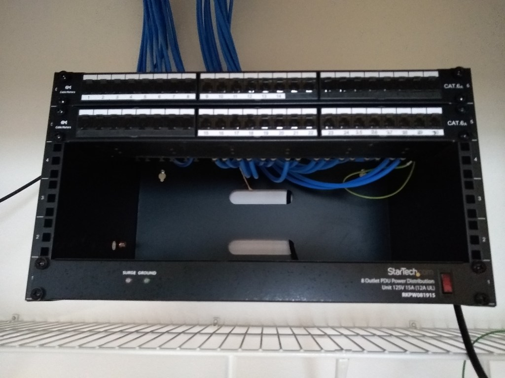
I’ve attached the cables to reflect the north/southbound orientation, so the top panel is labeled 1 to 14 starting from the left (north) and the bottom panel is labeled 15 to 30 starting from the middle and advancing to the right (south).
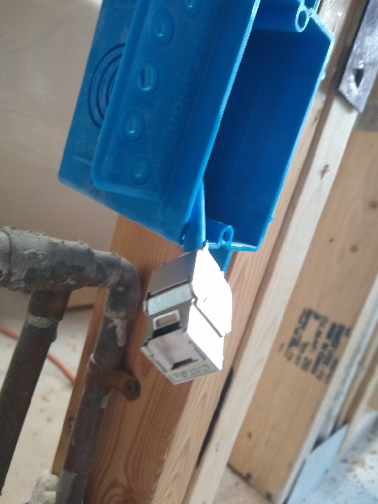
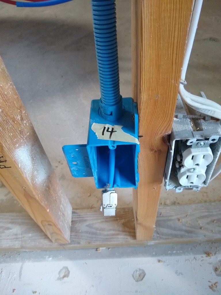
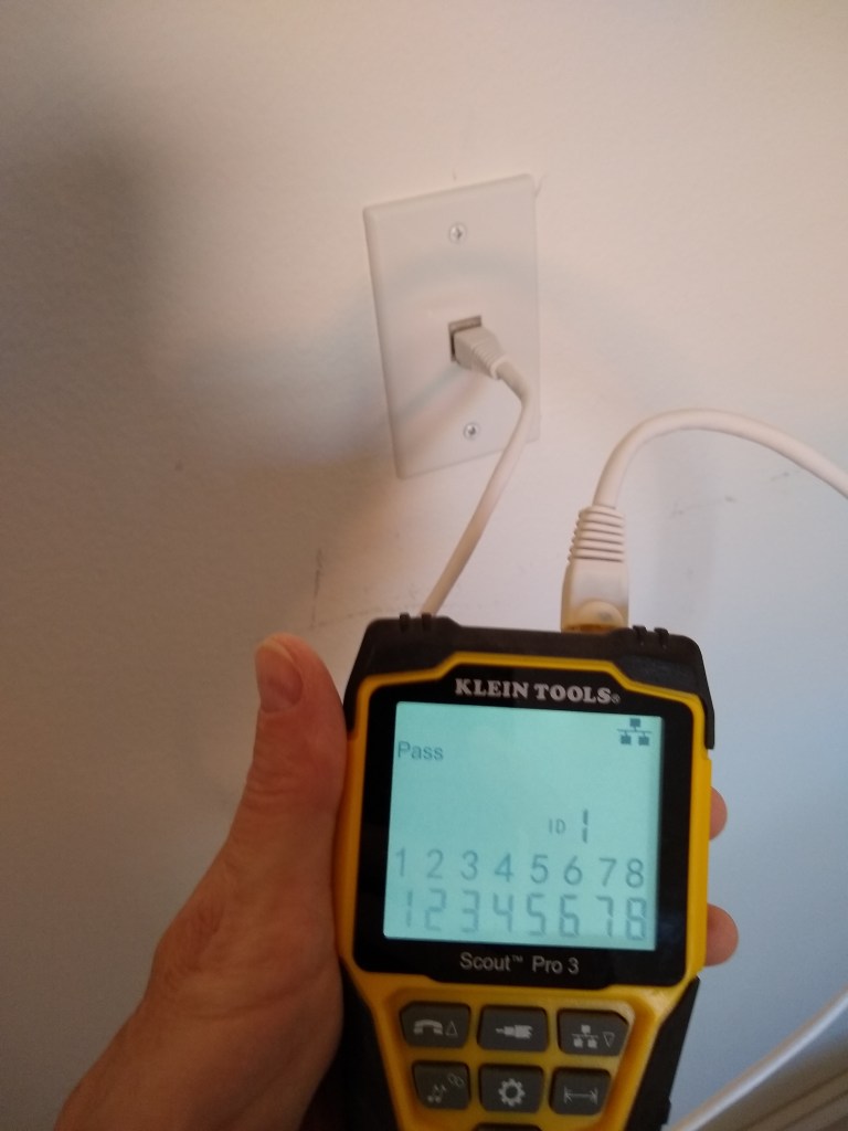
To give you a sense of what the other end of the cable will look like once attached to a faceplate, I took a picture of the one in the laundry room. This is the only place where there was still drywall in place (that I don’t plan on pulling down), so I could actually install the faceplate. This is connected to port 14 on the upper patch panel. You can see from the tester that all 8 lines are verified to be working.
This ends the cable termination process. I still have three slots available in the rack. One will receive a 24 port switch to connect 24 of the 30 lines to the router. Another slot will receive a battery backup unit. That will leave one free slot for another switch if I deem it necessary. I expect I will get another switch only if needed, even though it means some of the 30 lines will not be connected to the router. I can do that anytime and I suspect there will be several of them that are rarely used. Over time I will discover which lines I use and which ones I don’t. If I discover I need all 30 lines, I’ll add another switch and connect them. That’s the beauty of having a patch panel.
Now I need to add a new power outlet above the rack so the plug from the power distribution unit has some place to plug into. So electrical work is next.
