Final Inspection – July 2025

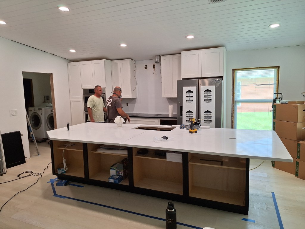
The countertop installers arrived on the first of the month. The started by placing the slabs on the base cabinets. The granite countertop, where the cooktop will be, was delivered with the opening for the cooktop not fully cutout in order to retain its integrity during transport. This can be seen if you look closely at the area the guys are facing in the image below, where they were preparing to cut that bit out to open up the space for the cooktop.

Slabs Placed on Base Cabinets

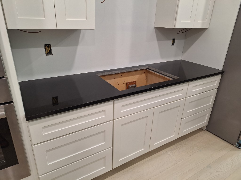
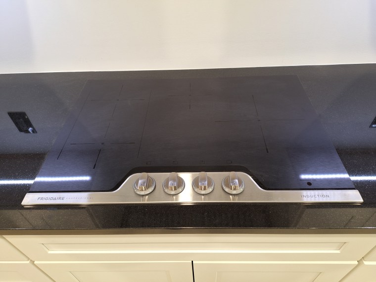
Here it is ready for the cooktop.

“Black Absolute” granite Installed

As for the island, there was a bit of a problem. At either end there is a hole for a 3″ popup outlet, (you can clearly see one of the holes in the first image above). While cutting one of the holes, they slipped, leaving a mark just outside the hole. They were hoping that, once installed, the part of the popup outlet that sits on the countertop would cover it up, but it did not. So this could have been a big deal, meaning the slab would have to be replaced. Before doing that, we decided to order a larger popup outlet (4″), expand the hole, and see if would cover the blemish. I was very skeptical that it would work because below the countertop there was very little room to expand the hole. That is, the hole was very close to the back of one of the cabinets, so I didn’t think there would be enough room to accommodate the collar that screws onto the outlet from below the countertop to secure it. Since the alternative was to scrap the blemished slab, there was no harm in trying. So we ordered a single larger popup outlet and waited for it to arrive.

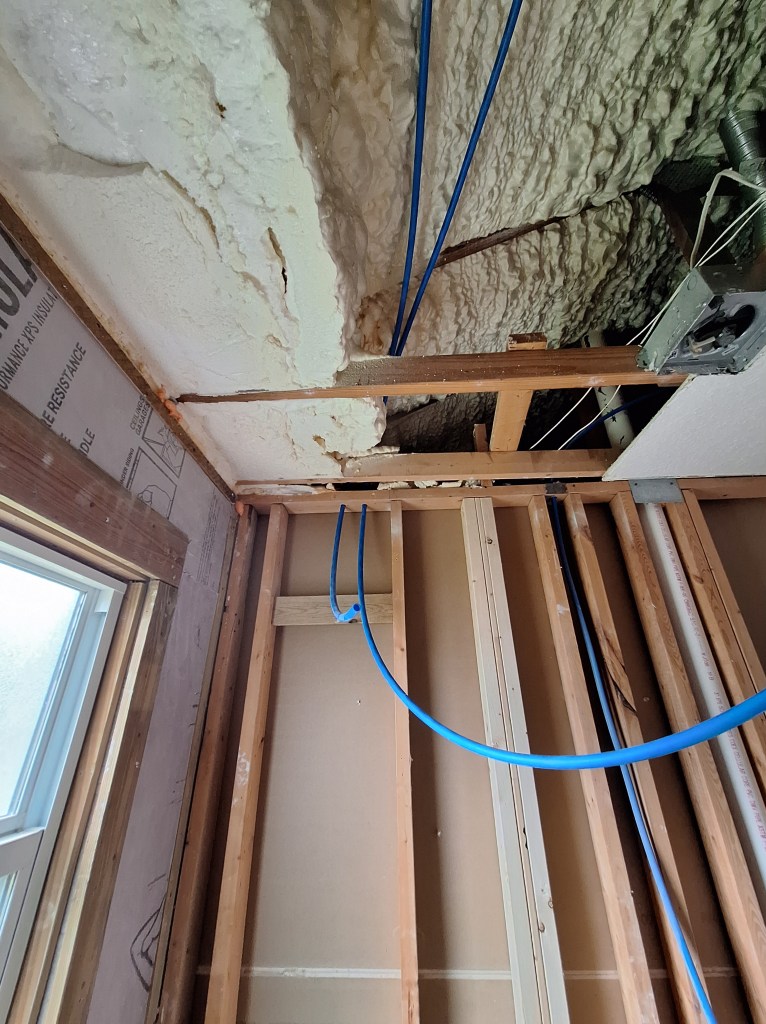
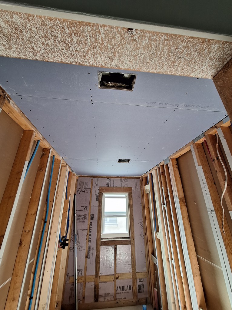
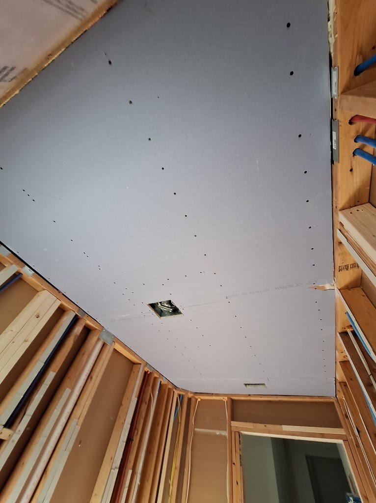
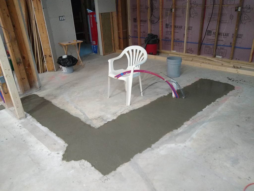
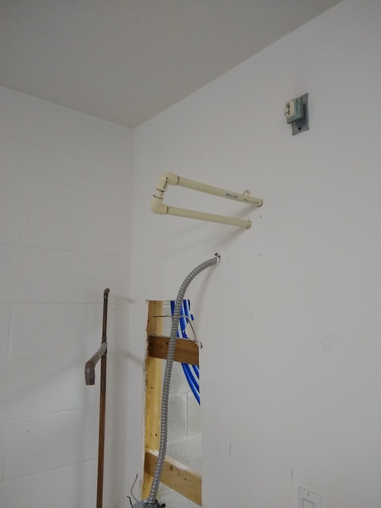
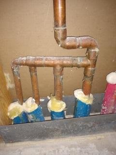
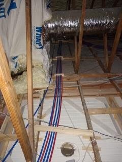
In the meantime, I returned my attention to the ducting that would vent the cooktop exhaust out of the house. In my last post, I had installed the small cabinet above the cooktop and originally planned to use flex pipe to connect it up, as shown below.

Flex Pipe Venting

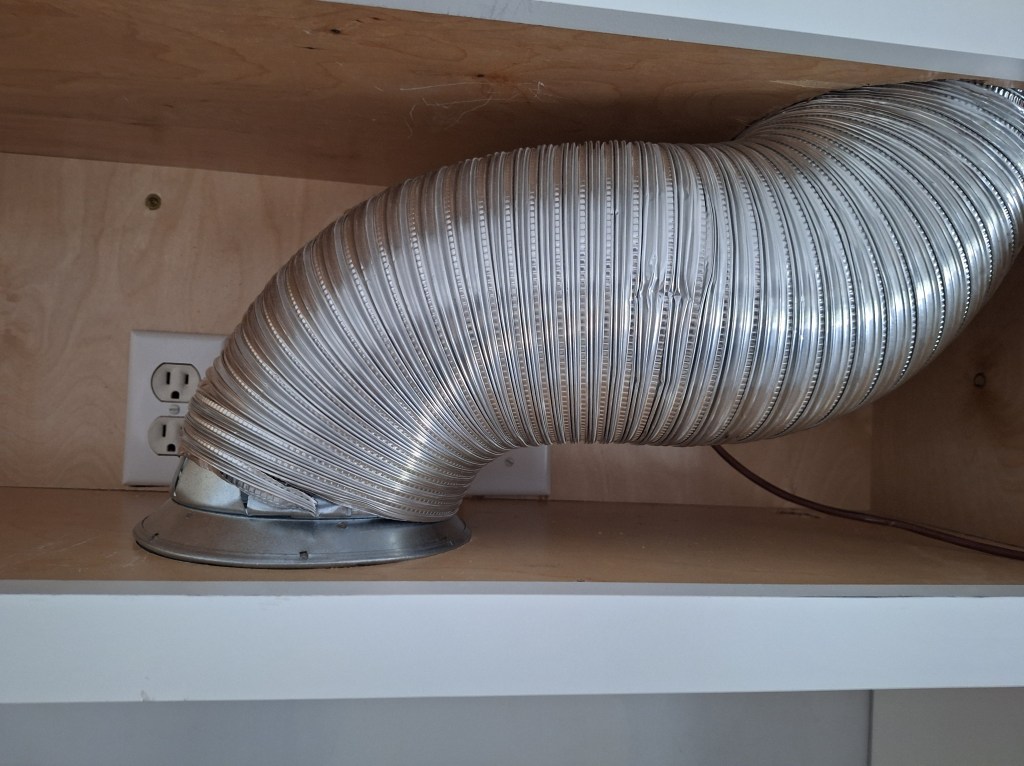
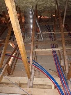
Unfortunately, this wasn’t going to work as you can see from the image. Not only that, but you’re not supposed to use flex pipe in this situation because the ridges in the flex pipe increase resistance to airflow, providing a better opportunity for grease to accumulate. I learned this by accident during a conversation with the guy who installed the wall oven. Given this, I sought to have custom ducting created to replace most of the flex pipe, as mentioned in my last post. I would not be able to replace all of the flex pipe. The portion that is above the cabinet and extends to the roof is no longer accessible, so it would have to remain and the new ducting would have to connect to it at the top of the cabinet. That, I believe, should be fine because the primary area of air flow resistance will be in the bend within the cabinet. Once the air exits the ducting within the cabinet, it is a straight run to the roof and out of the house. Fortunately, the custom vent ducting was completed at the time we placed the order for the new popup outlets, so I could switch over to that task while I waited. Unfortunately it wasn’t quite right, requiring a trip back to the fabricator.

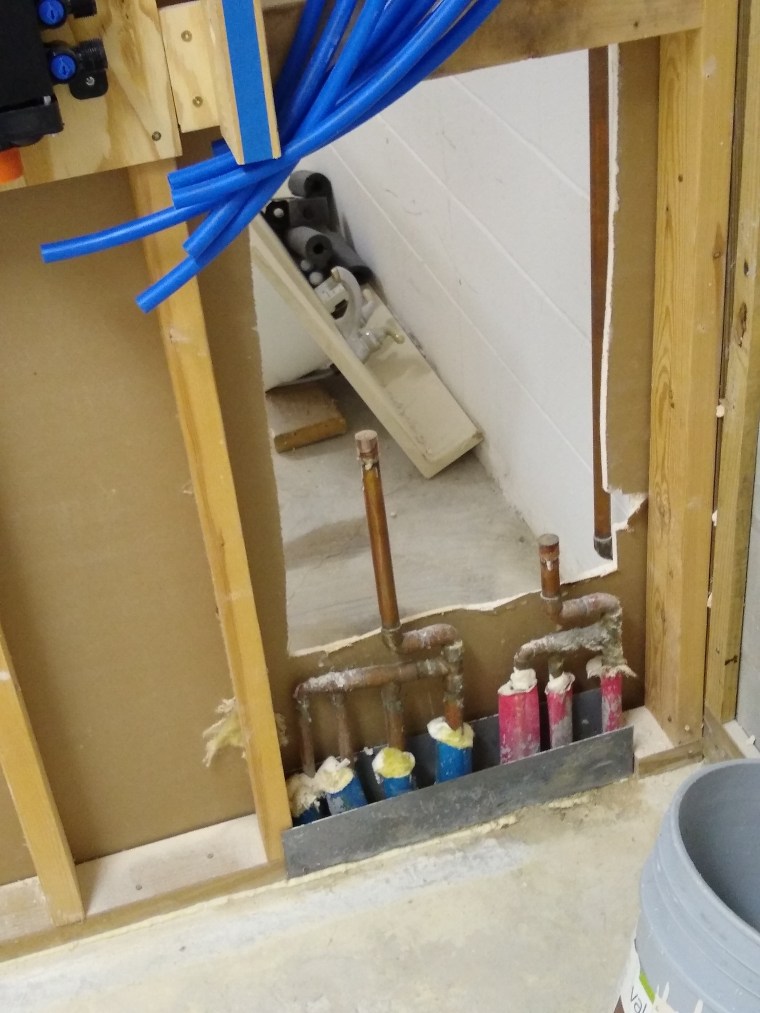
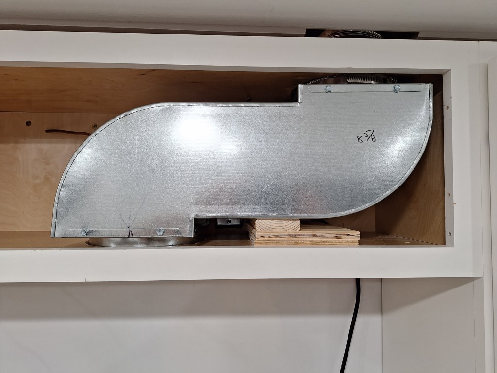
In the first image in this post, notice that there is no longer a cabinet above the cooktop countertop. I removed this because I needed to take it with me when I returned to the fabricator so they could see exactly what the ducting needed to fit into. I should have done this in the first place, but I hated to have to remove the cabinet. In the end, it was the right thing to do, and they got it right when I did.

Exhaust Ducting In Place

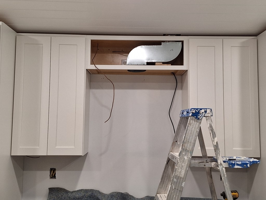
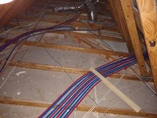
Above you can see the cabinet back in place and the new custom ducting in position. Here it is after I secured it in place.

Exhaust Ducting Secured

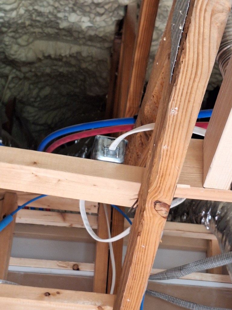
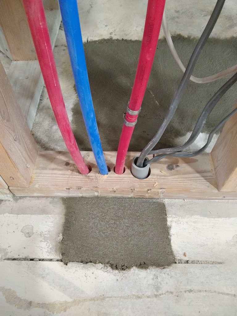
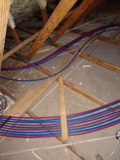
The wood underneath the ducting was placed there just for extra support. The outlet of the ducting is tied to the flexible pipe that extends out the top of the cabinet to the roof. It is secured using a metal hose clamp, as shown below.

Ducting Secured to Flex Pipe with Hose Clamp

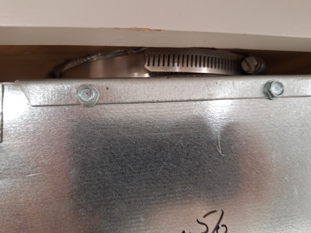
This turned out to be a much bigger challenge than I ever imagined. It was a tight squeeze, so I was very relieved that it worked out.

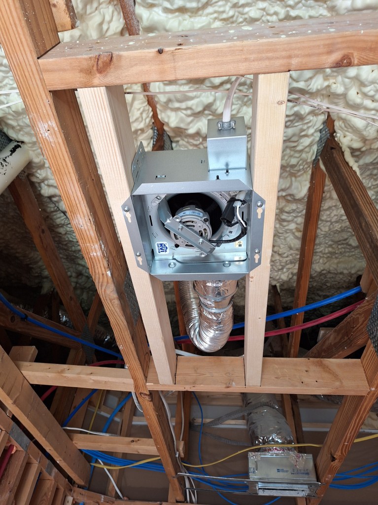
With the ducting secured, it was time to lift the exhaust vent into place and secure it to the bottom of the cabinet with four screws. I had a couple of friends help with this.

Exhaust Fan Installed
Exhaust Fan Installed and Cabinet Doors put back.

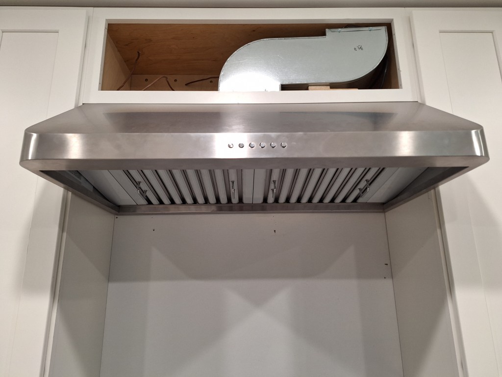
Getting that done was a big deal. I was so happy to have it checked off.

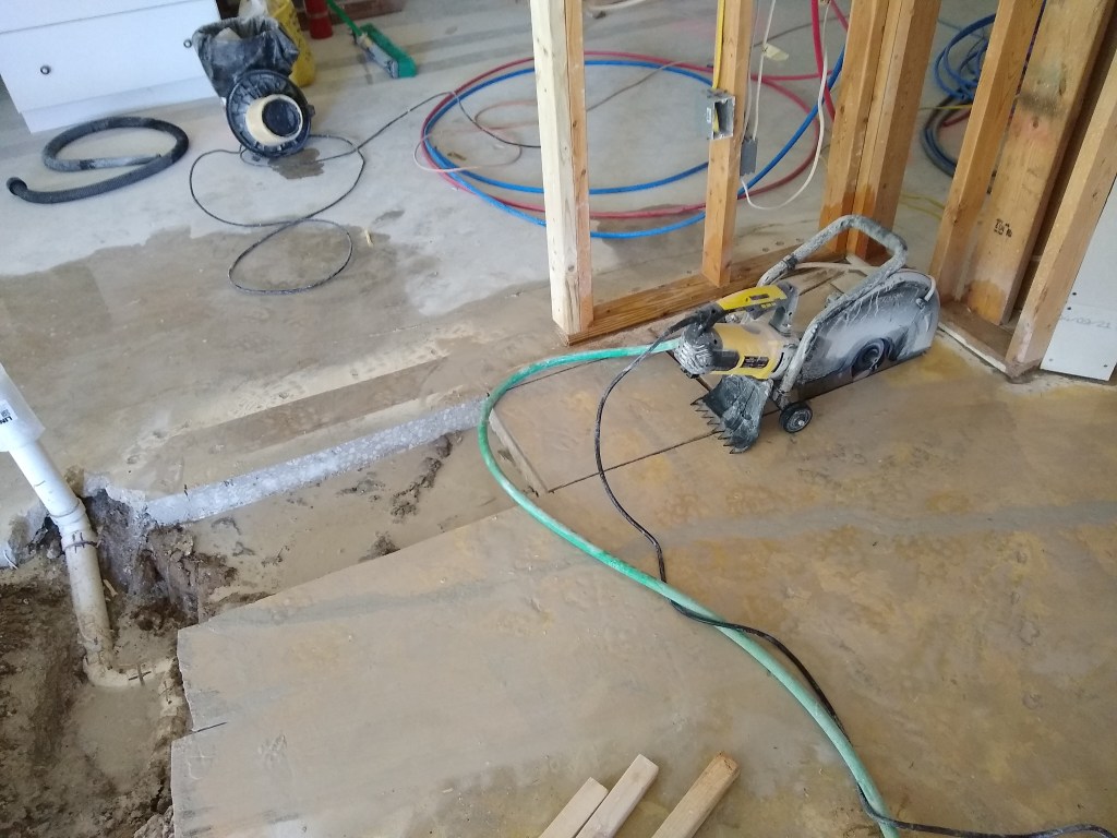
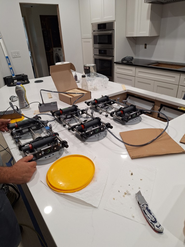
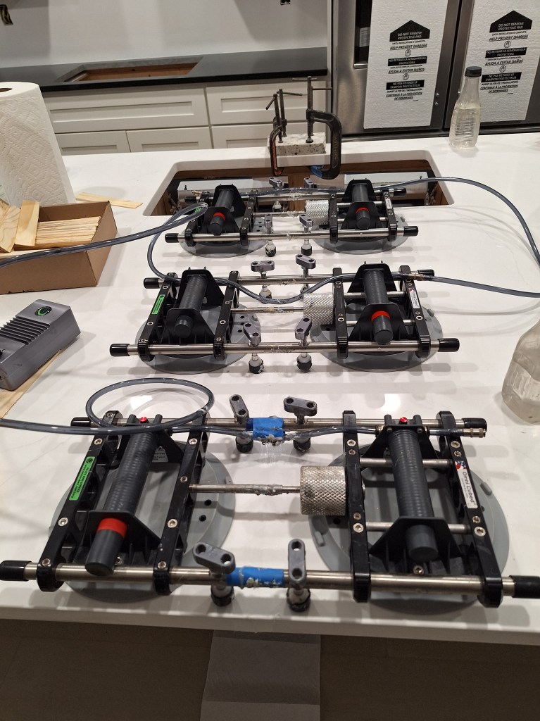
The next day the larger popup outlet arrived. They ordered a gray one because the white color, for some reason, would take longer to arrive. Since this was just to try it out, the color didn’t matter, so they ordered what would get here the fastest. They would return it once we’d determined if it would work. With the wider popup outlet in hand, the guys got to work widening the hole. To my pleasant surprise, it worked, and we did not have to replace the slab. So the guys could start setting the seam between the two slabs. In the image below you can see the equipment used to pull the slabs together. You can also see the gray popup outlet in place at the end of the slab.

Setting the Seam

Once aligned to their satisfaction, glue is applied and the two seams brought together and left overnight (Thursday, July 3rd).

Seam Set

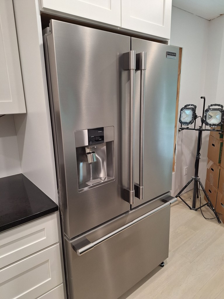
The two white popup outlets were expected to arrive on Saturday, July 5th, so there was a day in between, July 4th, that I used to install the refrigerator before I headed out to celebrate Independence Day.

Refrigerator Installed

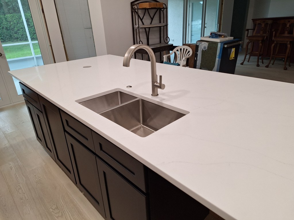
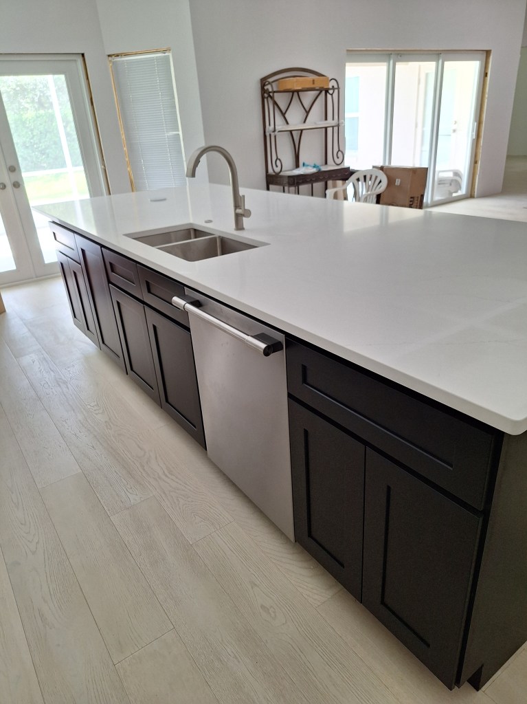
The next day the guys returned to finish the installation, which involved polishing the seams, installing the undermount sink, and cleaning it all up. After they left, I put in the faucet and the pressure switch (to the left of the faucet) that will control the in-sink garbage disposal.

Countertop Installation Complete
Sink, Faucet, and Pressure Switch Installed

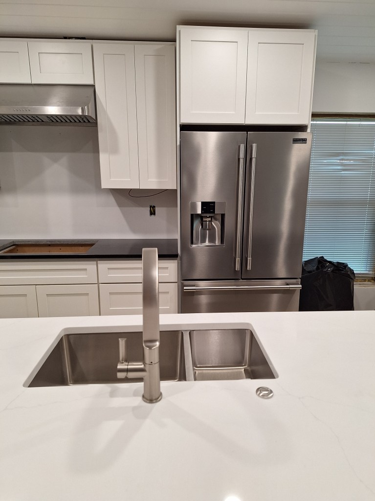
The two white popup outlets arrived the next day and I put them in place and plugged them into the outlets below the cabinets.

Popup Outlets Installed
Popup Outlet popped up

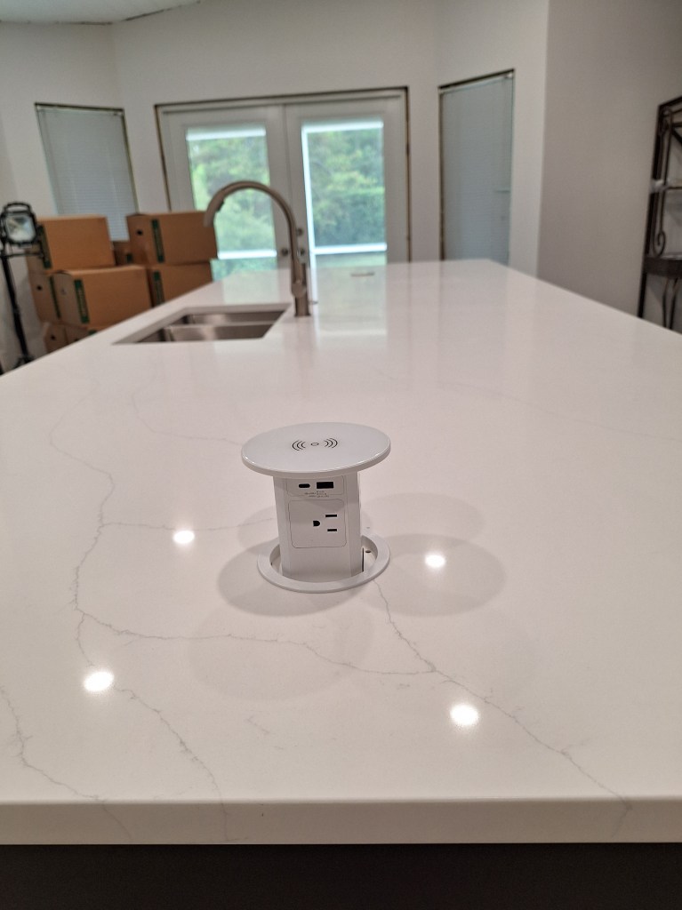
Note that these outlets also provide USB ports and can charge a phone by simply setting the phone on top of the outlet, whether popped up or not.

With the countertops and sink installed, I arranged to have a plumber install the plumbing for the sink and install the dishwasher. I entertained installing this by myself, but it would be a complicated install. As I later discovered, this was a good call, which you’ll see shortly. But before that happened, the mirror for the the master bathroom vanity arrived and was installed.

Vanity Mirror and Lights Installed
Vanity Mirror and Lights Installed – lights on

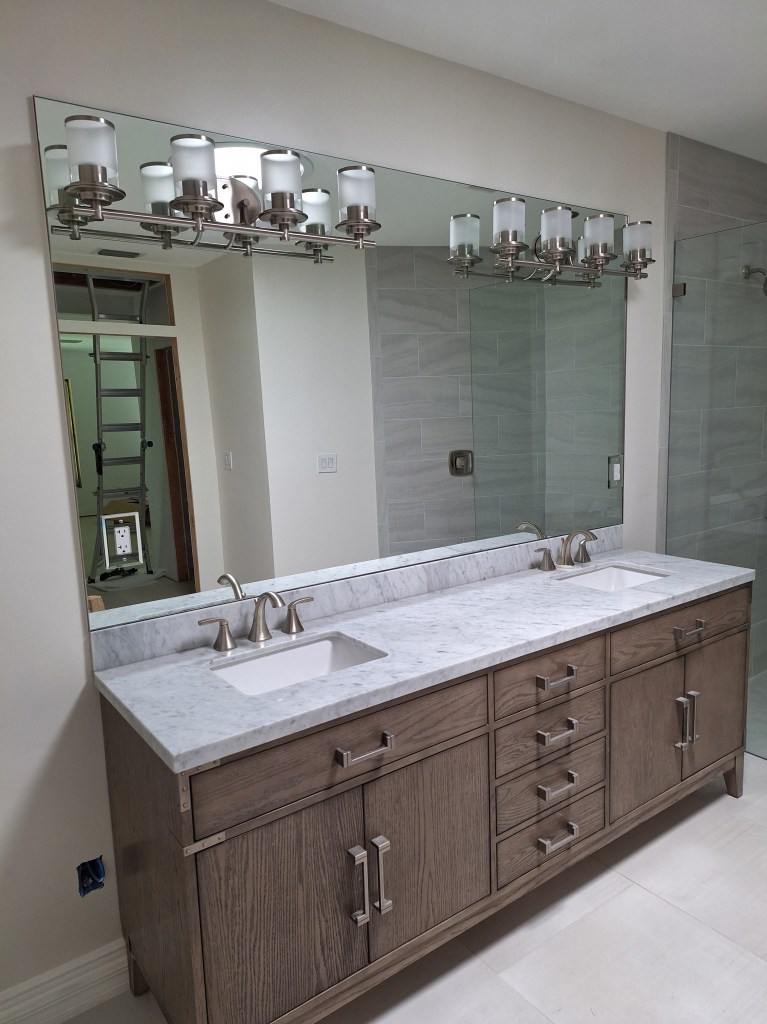
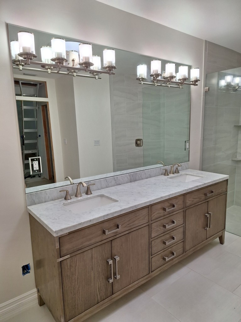
The interesting thing about this installation was that the company insisted that they install the vanity lights. Since the lights are on the mirror, they did not want the customer to mess with it for fear that if they over-tighten them, it could break the mirror. So I was completely hands off for this, which was fine by me. It was a two person job, as you’d expect, and took about two hours. I like it.

A couple of days after the vanity mirror was installed, the plumber arrived and hooked up the supply lines to the sink and dishwasher, the in-sink garbage disposal, and the drains for all of it.

Plumbing Under the Kitchen Sink

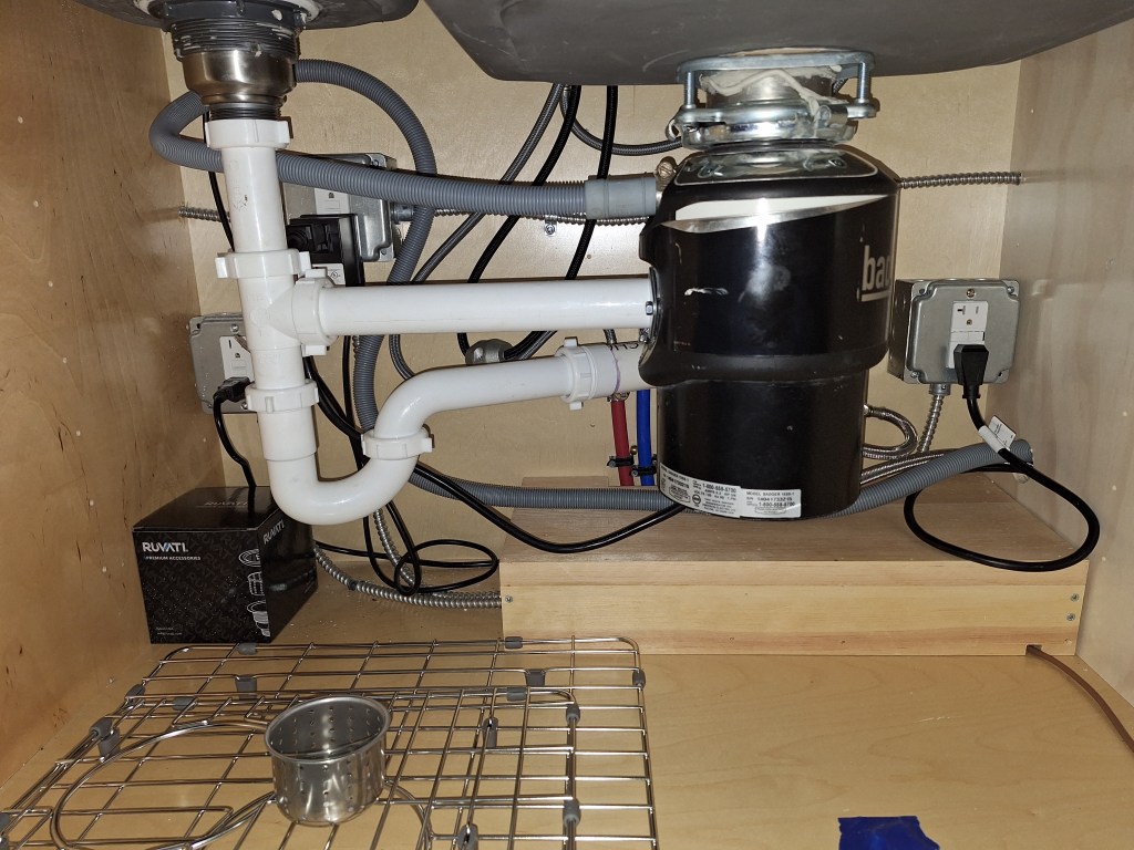
As you can see, there is a lot going on here. We decided to locate the garbage disposal under the large sink because installing it under the smaller one would have meant that the drain from it to the main drain would be too steep a slope. When too steep, the water separates from the solids too quickly, which can result in clogging.

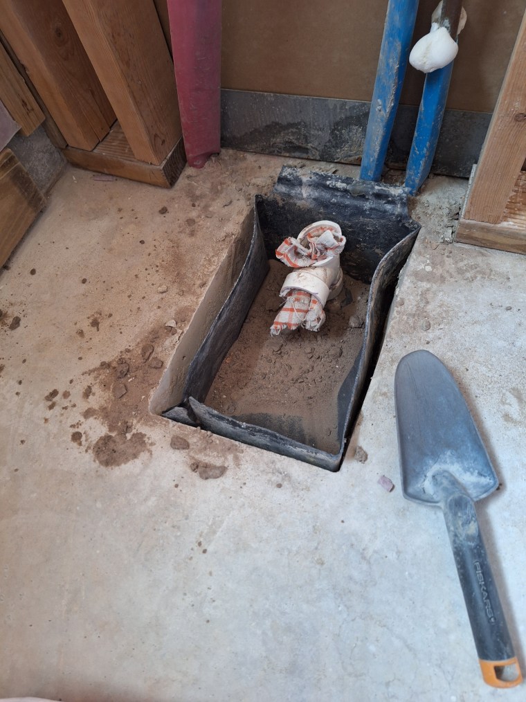
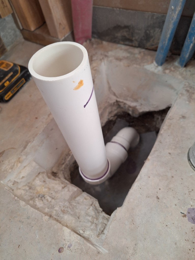
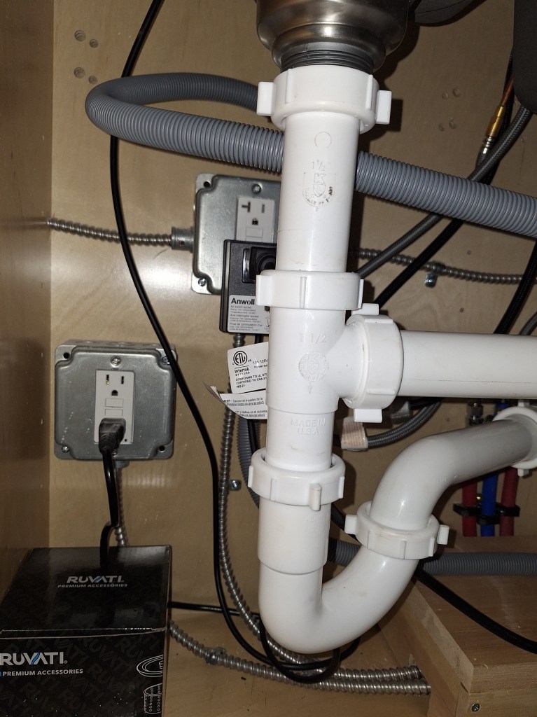
Below I am showing a closeup of the P-trap. The large sink drains through the garbage disposal into the drain under the small sink, where the P-trap resides. The output of the P-trap connects to the main drain that continues under the concrete slab and out to the street sewage system. Behind this you can see a black box plugged into the outlet. Into the black box is plugged the garbage disposal. This black box connects to the pressure switch above the countertop (shown in a previous image above), which, when pressed, switches the garbage disposal on/off. The plug below and to the left is for the kick plate lighting, which was discussed in a previous post.

P-trap Under Small Sink

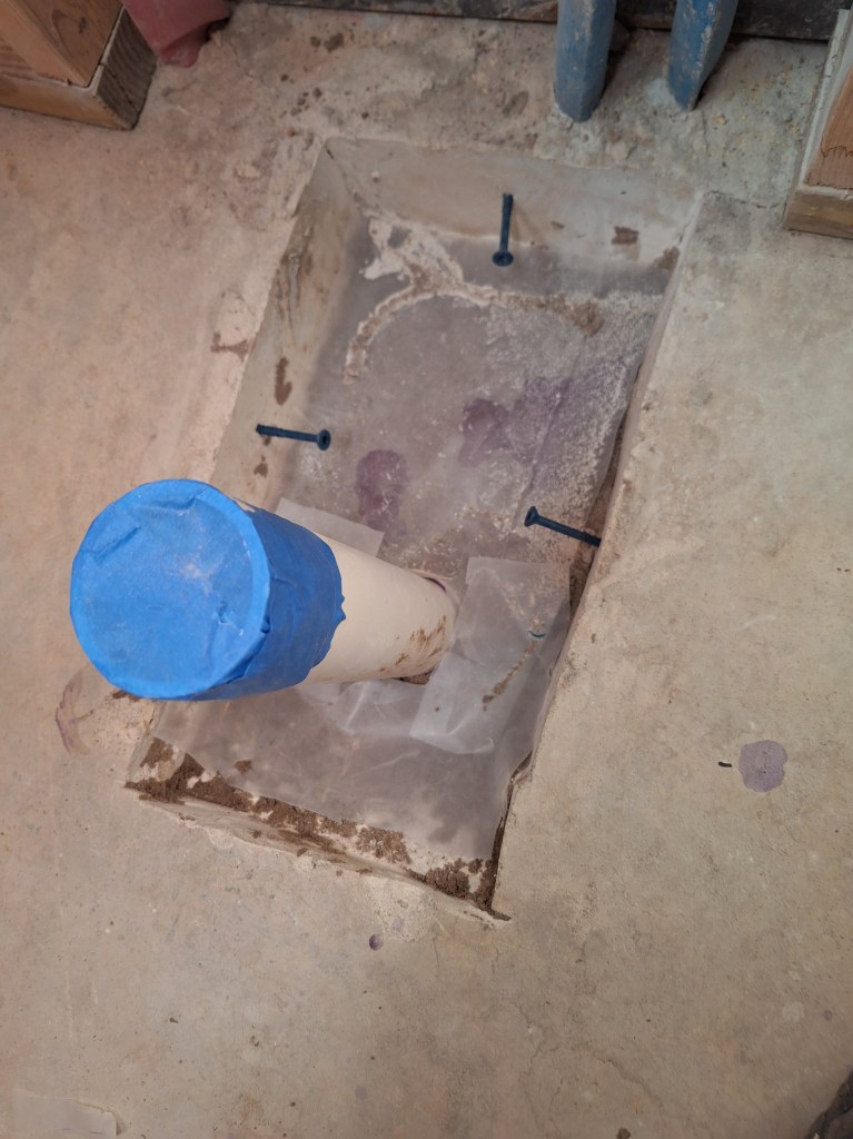
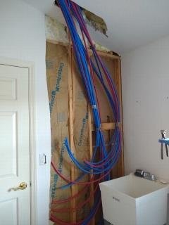
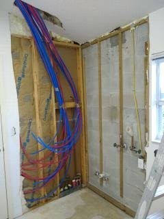
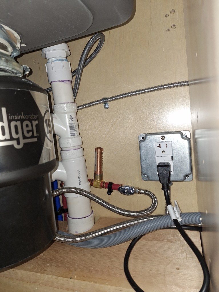
Below you can see the where the drain emerges from below the cabinet. At the top of it is a Studer Vent. Plumbing vents act as pathways for air to enter and exit the drainage system. This helps maintain balanced air pressure, preventing a vacuum from forming that could hinder water flow and cause drainage issues. They are normally inside a wall cavity and extend out through the roof of the house. Since this is not available in an island, the Studor vent comes to the rescue. It provides the venting function while preventing sewer gases from escaping.

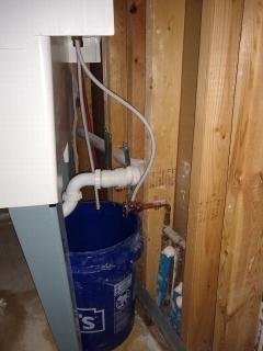
You can also see below that a water hammer arrestor (the copper thing) is installed along the water supply like for the dishwasher. This is needed because the dishwasher will turn the water on and off suddenly, which can result in “water hammering”. So this device will prevent that.

Water Supply, Drain, and Power for Dishwasher

Finally, here is the thing everyone sees; the dishwasher.

Dishwasher Installed

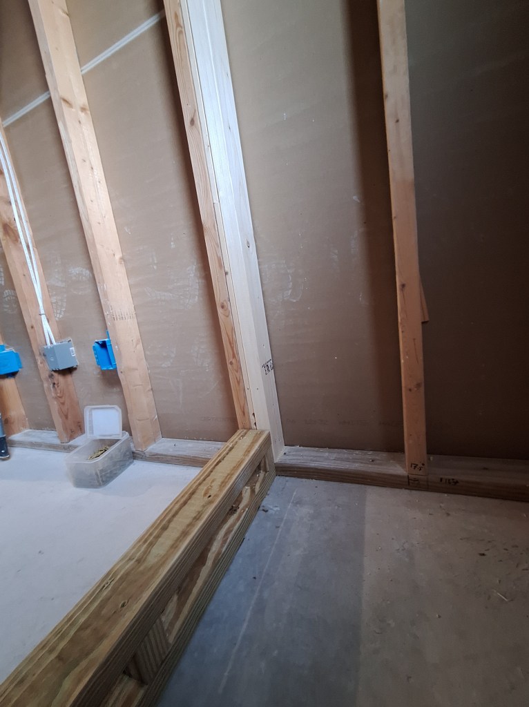
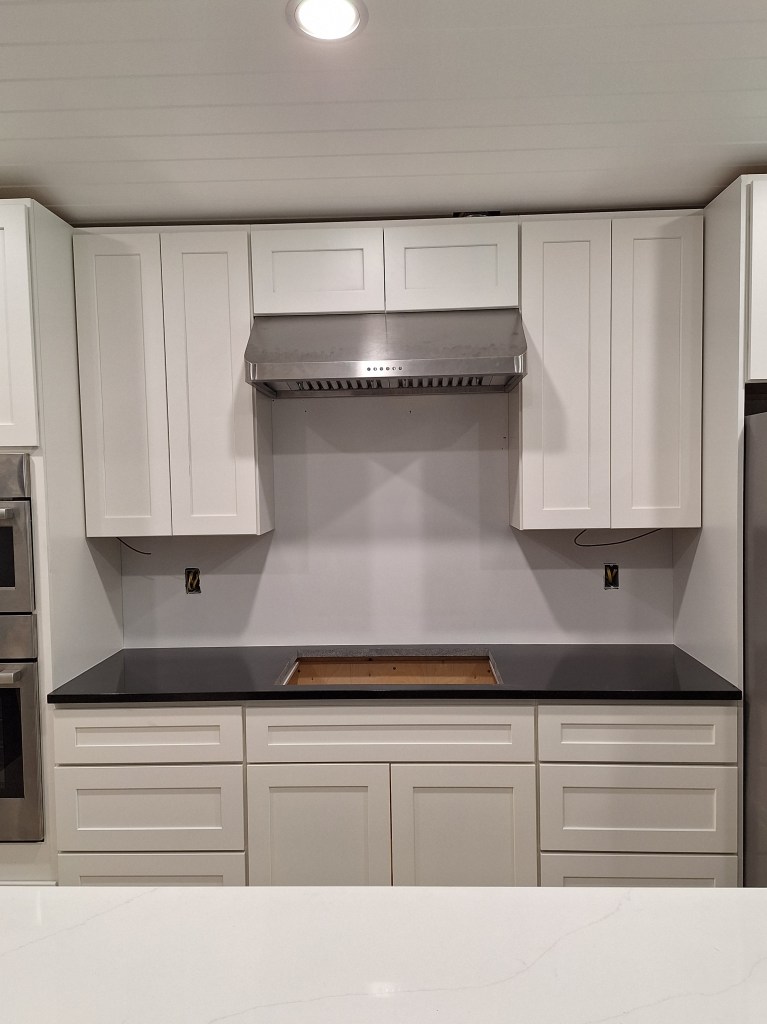
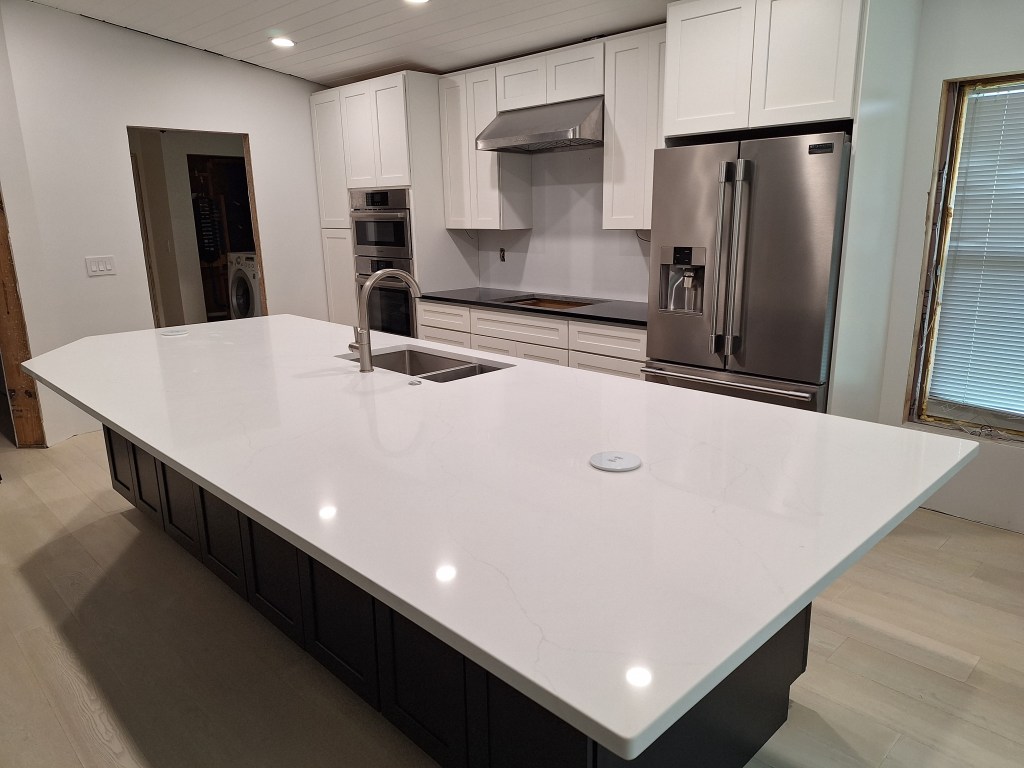
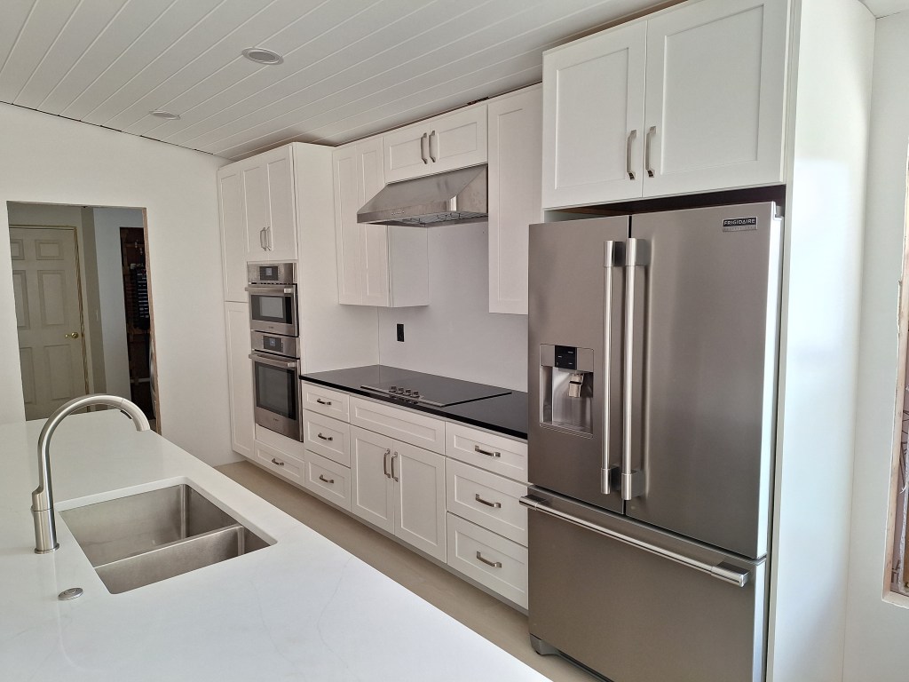
With this done, I have a functioning island. The last thing required to make the kitchen fully functional was the installation of the cooktop. However, before that could be done, I needed to add a backsplash on the wall behind where it will go. I intended to add white tile with black grout to that area, but after a warning from the tile supplier about how difficult it will be to keep clean I decided to abandon that plan and instead extend the black granite up the wall. There is likely to be a lot of splatter on that wall, and granite with no grout lines will be much easier to clean. That decision, however, meant that I would not be installing the backsplash anytime soon. The granite will have to be sourced, and the fabricators will have to do their thing, etc. The backsplash, however, is not something that requires an inspection, so I went ahead and installed the under counter lighting, cooktop, and outlets in that area so that I could schedule an inspection.

Cooktop, Outlets, and U/C Lights Installed.
Closeup of Cooktop

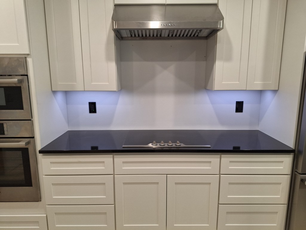
As you can see, the outlets are black, so they will blend in with the black granite once it is placed on that wall.

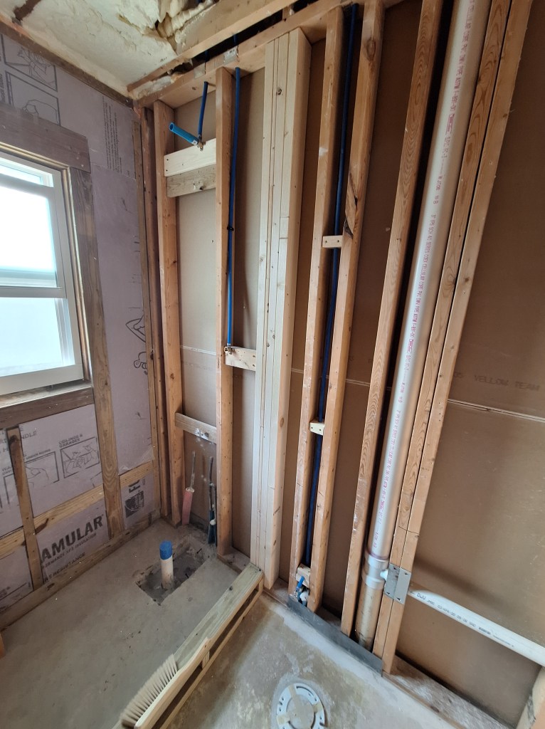
I ordered the cabinet pulls for the kitchen. The ones I liked were surprisingly expensive, but I got them anyway. Apart from installing the backsplash and cabinet pulls, my work in the kitchen was done, for now. My inspection was scheduled for Monday, a few days from now. So I turned my attention to the guest bathroom, installing the shower head and wand.

Shower Head and Wand Installed in Guest Shower

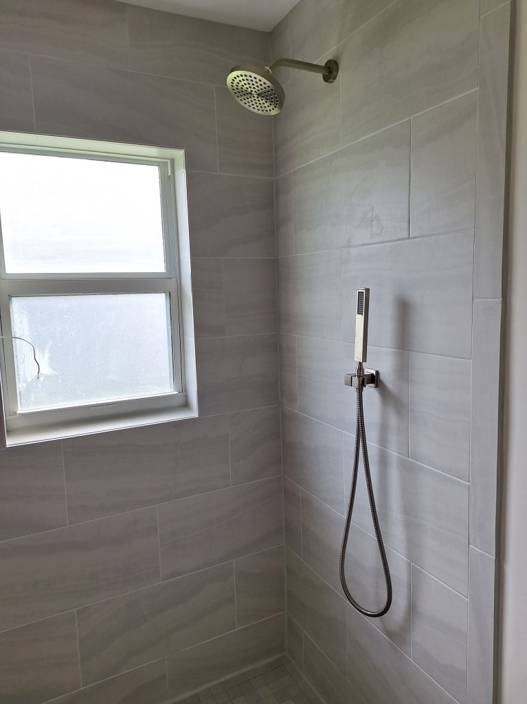
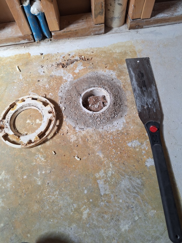
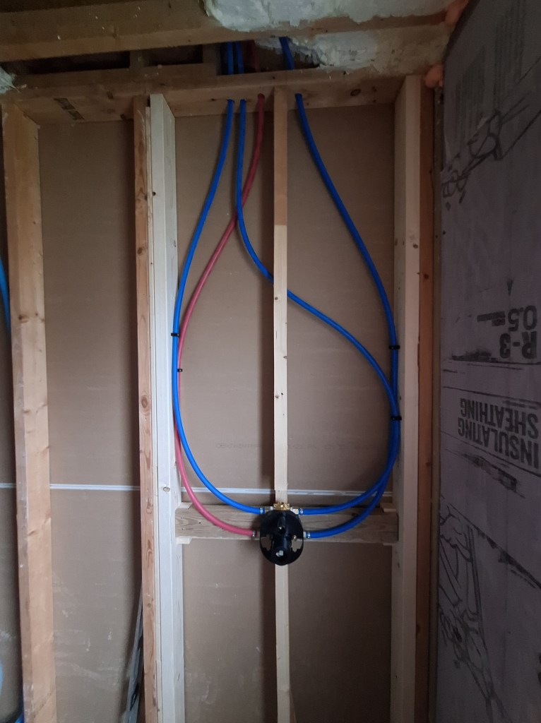
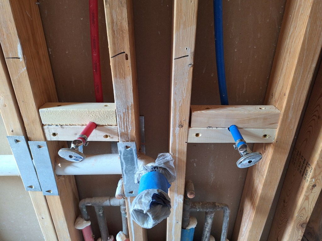
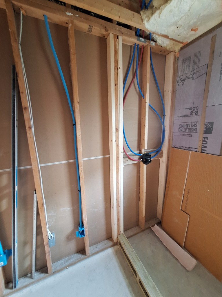
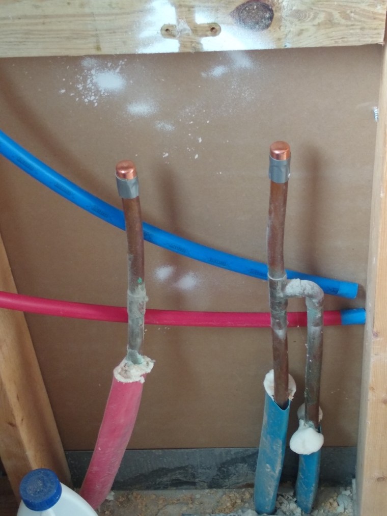
There is a bit of a story with this. Both the shower head and wand have separate water supply lines. Each line connects to a “bent ear elbow” behind the wall. When I positioned the two elbows, I estimated where they should go. Unfortunately, I set them back too far, meaning the threads for both the shower head and wand holder could not reach them. This was not an issue for the shower head because I was not keen on the rain shower head I had purchased. It was kind of fancy and attached to the wall with an extended version of the holder for the shower wand. More than that, though, I wanted a shower head that was not limited to just a rain head. So I decided to replace the one I had with one that had both a rain and a traditional stream (achieved by rotating the shower head). This also came with a traditional shower arm, which meant it would easily reach in and connect to the recessed elbow. It was not a perfect color match, but close enough.

Shower Head

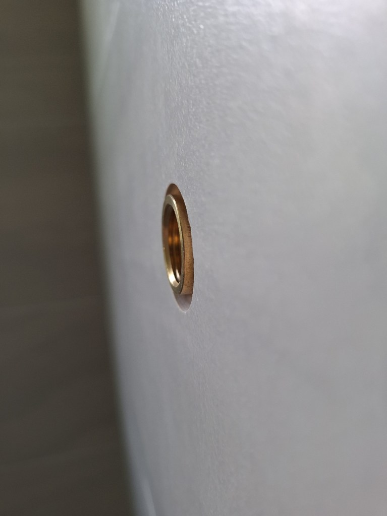
However, there was no such option for the wand. The threads of the wand holder were not long enough to reach the threads you see in the image below.

Drop Ear Elbow Recessed behind the Tile

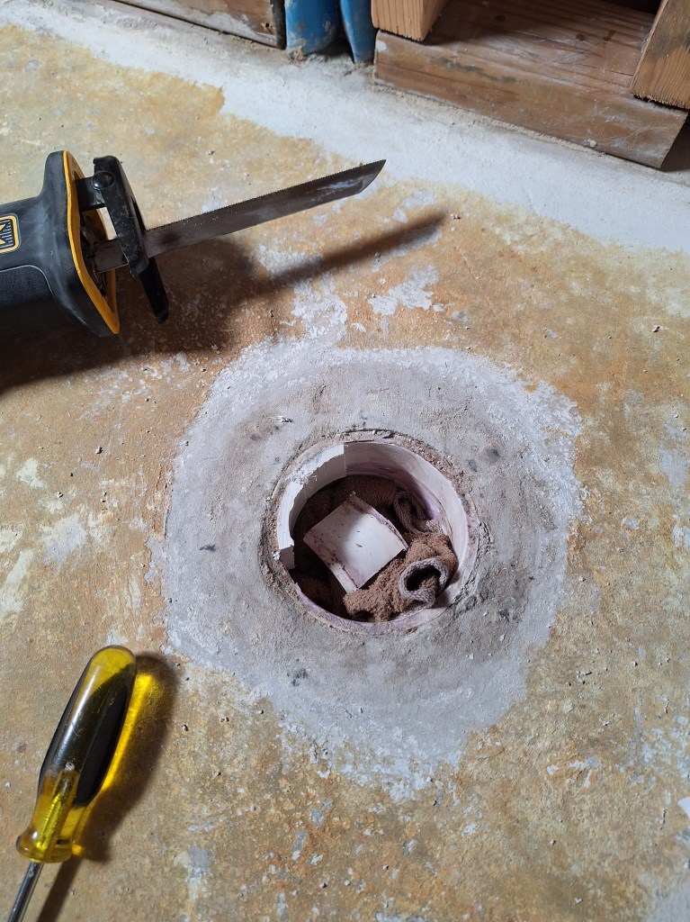
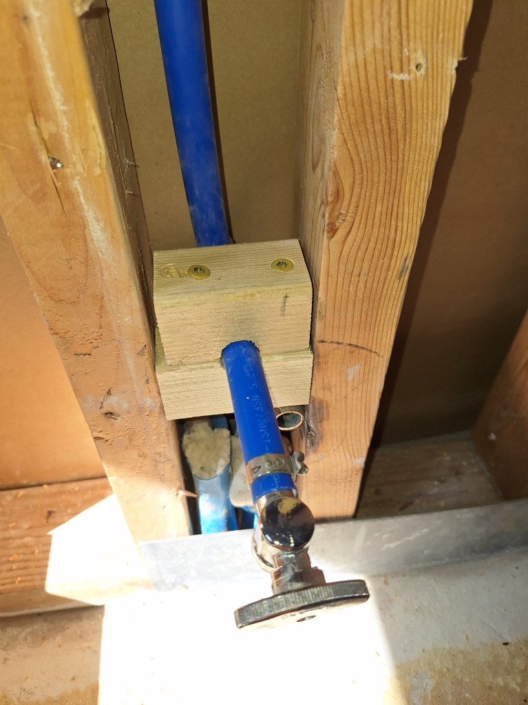
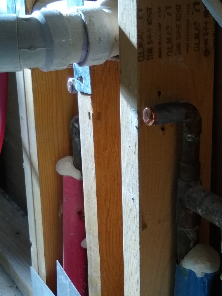
To fix this, I purchased an adapter to bring it out to the level of the tile. In the image below, you can see that it actually comes out just beyond the surface of the tile, but this is well within tolerance because the flange for the wand holder would cover it.

Adapter Added

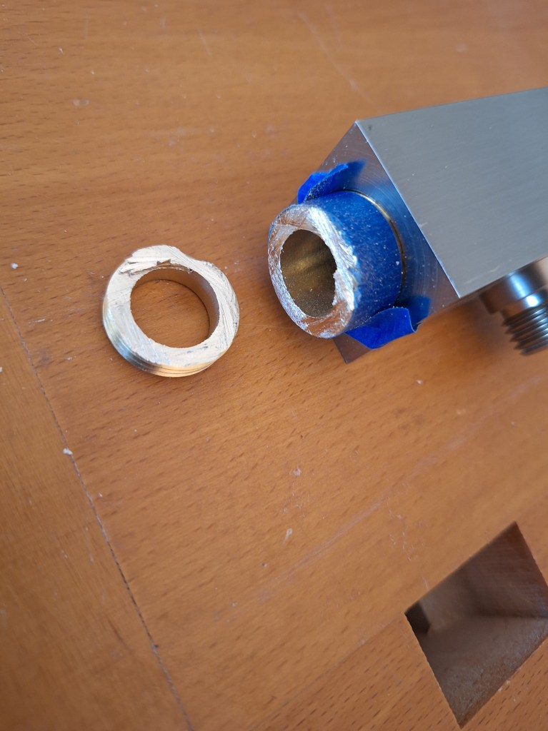
Unfortunately, the threads of the wand holder were too long and, when fully seated in the adapter, the holder extended too far to be covered by the flange.

Threads too Long

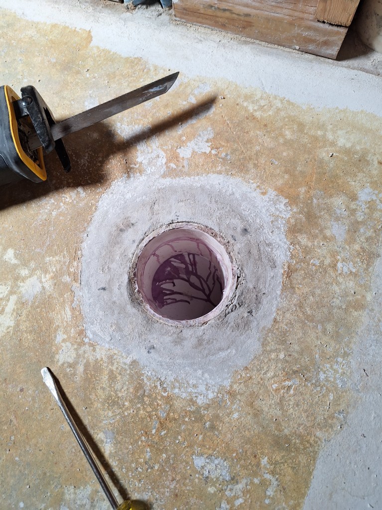
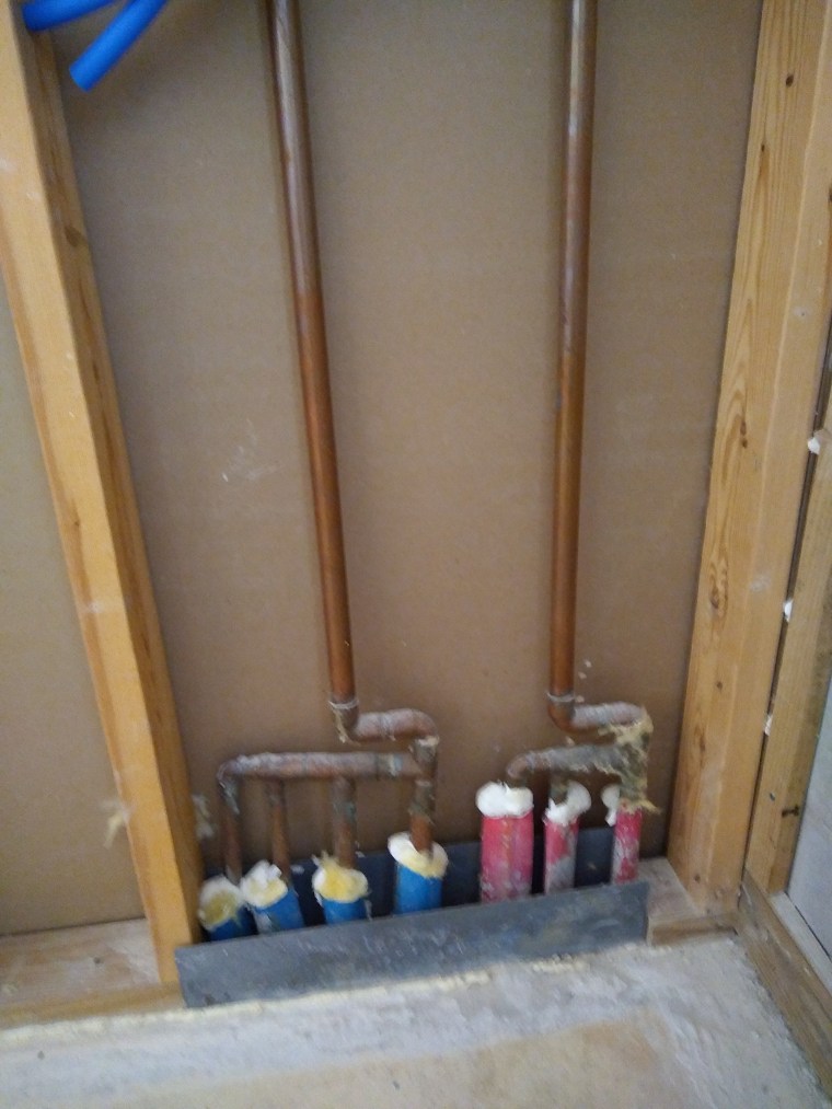
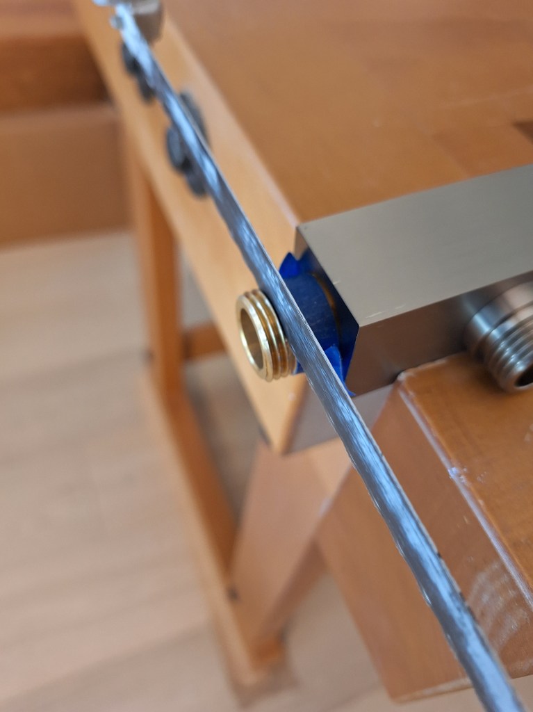
As it was, this was unusable and looked like I’d have to replace it. After some thinking, I decided to try cutting off some of the brass threads. Since I figured I was going to replace it, I might as well give it a shot. So I pulled out a hack saw and sawed off a section, careful to keep the threads in tact.

Cutting the Brass Threads
Section of Brass Threads Removed

Although it looks a bit messy, I didn’t have to do any work with a file to clean it up. The threads engaged nicely with the threads in the wall, resulting in a nice fit. It protruded just a bit, but that was easily covered by the flange, as you can see in the image below.

Shower Wand Installed

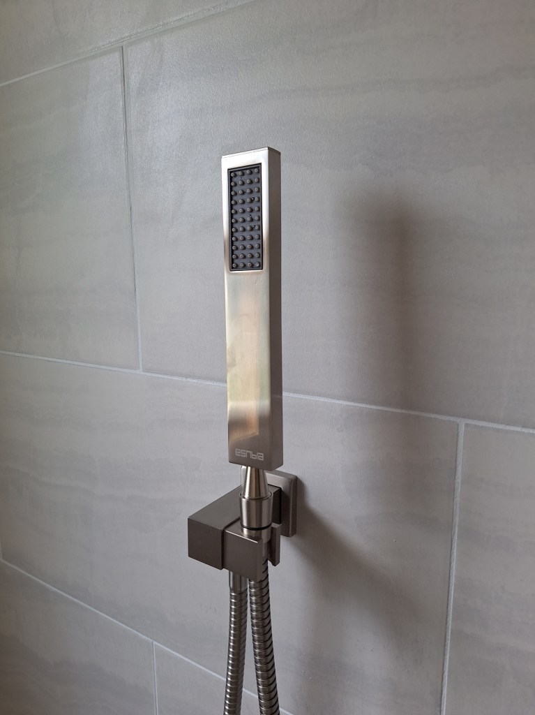
I was pretty happy about this. I thought this was going to be a major headache. To have it come together like that was very pleasing.

My cabinet handles arrived, so I got to work installing them. I installed all but the ones that will be going on the cabinet doors that I am having replaced. A few of the doors had defects. Given that there is a 5 year warranty, the company has been notified and they will eventually send me replacements. So in the images below where no handles are present, those are the doors that will be changed out once the new ones arrive.

Handles Installed
Handles Installed

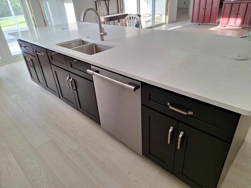
Note that on the other side of the island there are also cabinet doors, but they will not be getting handles because those cabinets will rarely be used and adding handles might present an obstruction for ones knees while sitting at the counter. They can be opened by pulling on the bottom edge of the door, when needed. Also, from the vantage point of the living room, I think it looks better without them.

My inspection resulted in the approval of the electrical and mechanical. The plumbing and final inspection had to wait because the inspector had trouble finding the stamp on the glass wall of the master shower that shows it is tempered glass. That was resolved the next day, so I scheduled another inspection, which resulted in the approval of what was remaining. So I am finally done with inspections, which is a really big deal. I am free to move in when I’m ready and can proceed with whatever project suits me without regard to permit expiration dates.

The lease on my apartment ends mid November, so I will use the time between now and then to work on anything I feel I’d like done before I move it. However, I am at the point now where I could move in because the remaining projects are ones I can and will do while living in the house.

The timing of this worked out well, as I am going on vacation for about ten days. So it’s a nice way to start that. When I return, I think I’m going to focus on the garage and setting up the workshop I need to address the upcoming project. That will be fun.

Guest Bathroom – October 2024

Having made the master bathroom functional, it was time to get started on the guest bathroom. This was the last room in the house that had been untouched since the demolition long ago. I left this room until last because it was where the only working toilet and sink resided. Now that the toilet in the master bathroom is functional, the one in the guest bathroom was no longer required. Similarly, with a working utility sink in the garage, I had an alternative to the one I had temporarily installed in the guest bathroom. Still, I wasn’t planning to remove either of these appliances until absolutely necessary.

The first thing I did after cleaning out the space, was to relocate the shower supply lines. I put them in place back when I was running the PEX throughout the house, and simply placed them on the wall where the original pipes had been. You can see this on the left side of the image below.

Shower Pipes Original Location

This bathroom originally had a bathtub/shower setup, so it made sense for the valve to be on that side of the wall. However, I no longer wanted a bathtub. All I wanted was a walk-in shower, with a curb. This meant that it made more sense to locate the valve, and therefore the supply lines, to the opposite wall, where you could set the temperature without having to be in the shower. To accommodate that, I pulled down some of the ceiling.

Making Room to Reroute the Shower Supply Lines.

As you can see, there is a lot of spray foam up there, leaving little room to maneuver the PEX pipes. Opening up this area made this much easier, and I didn’t have to climb up into the attic to do it. In the image above, you can see the two supply lines dangling down from the ceiling on the left, which is the south wall. They will be fed down through the top plate of that wall once the framing work is done and I know where I will be placing the valve. But before that, I placed some foam board insulation against the exposed concrete blocks.

Foam board Added

Next, I removed the toilet in order to get greater access to the shower area. It was a bit sad to remove the toilet because it worked flawlessly for so long. It had been my only working toilet since I started this renovation and it always just worked. I never even had to change the flapper.

Original Toilet Removed

With the toilet no longer in place I removed the last of the drywall and tile that that surrounded it.

Tile and Drywall Removed

The original toilet flange held up well. It was set in place more than twenty years ago. It will be replaced.

Original Toilet Flange

I removed the toilet flange using a pull saw. This worked extremely well, leaving the flange barrel flush with the floor. I stuffed a towel down the drain to prevent any debris from falling in.

Cutting Off the Flange
Flange Cut Off

The barrel of the flange was removed by using my reciprocating saw to make vertical cuts, being careful not to cut into the drain to which it was glued, then chipping it out using a screwdriver. This was much easier than I expected. The pieces broke away easily.

Removing Flange Barrel
Flange Barrel Removed

With the toilet removed, I had room to install the shower curb.

Shower Curb Installed

This being a much smaller bathroom than the master bathroom, a curb makes sense here to contain the water. In anticipation of the glass wall and door that will enclose the shower, I added additional framing on either end of the curb.

Curb and additional Framing – South Wall
Curb and additional Framing – North Wall

The curb is made from pressure treated lumber. Since it will be covered in a water proofing material, only the wood touching the concrete floor needed to be pressure treated, but I chose to make the entire thing from the same material. To the right in the shot above, you can also see that I temporarily covered the toilet drain with a flange and plug to make sure nothing falls into it. This flange will not be the one I use in the end, because it is too small, but it serves as a protective cover for now.

Next, I installed the shower valve.

Shower Valve Installed

As you can see, in order to position the valve centrally on that wall, I had to cut a notch in the center stud to make room for it. I also added another stud along the outside wall in order to provide more area to attach the waterproofing board (Kerdi Board).

I brought the hot and cold supply lines down through the top plate, but it was extremely tight, especially for the cold line (blue). The two lines that leave the valve and travel overhead to the opposite wall would have to be done in a more round about way.

Supply Lines to the Valve
Supply Lines from Valve to Shower Head and Hand Held Wand

Given the tight spacing, I had no choice but to run the two traveler pipes to the valve as shown below.

Supply Lines Connected to Valve

I also made a change to how I brought down the two travelers to the drop ear elbows.

Supply Lines Connected to Drop Ear Elbows

If you look a couple of pics up, you’ll notice that I originally ran the two lines down the preexisting holes in the top plate. After deciding where to place the blocking for the shower head and hand held wand, I moved them to more directly align.

With the supply lines in position, I started looking at the drain situation. Since there was a tub/shower in place before, the drain needed to be replaced with one suitable for the shower, which meant pulling out the existing 1-1/2″ drain and installing a 2″ drain, as required by code.

Existing Drain for Shower/Tub

Below you can see how the fitting I just removed has an inlet for the drain and another for the overflow drain of the tub. The remaining stub goes down about 12″ to the bottom of the p-trap.

Tub Drain After Removal

Below I show the new arrangement that will tie into the remaining stub.

Drain Fittings Dry Fit

As you can see, it sits way too high. This is made even more clear when the drain itself is added.

Drain Dry Fit

Even after the shower pan is added, I would still have to lower the stub by close to 8″ to accommodate this, which meant cutting out the concrete at the bottom of the box. It also appeared that once the drain flange was added and this whole assembly was lowered, it would come into contact with the front of the box. So the front edge of the box would have to be chipped a way a bit to make room for it.

I began by using my angle grinder to score a series of lines as deep as it would manage. After that, I used my small jackhammer, and the pieces broke away quite easily.

Cutting Away the Concrete

I continued in this way until I had cleared away everything around the existing 1-1/2″ riser pipe.

Concrete around Pipe Removed

Next I removed the dirt from around the pipe until I reached where it connected to the p-trap. I wanted to go as low as possible and still have something to connect to. Once the dirt was removed, I placed the dry fitted assembly roughly in position to determine if I needed to expand the front edge to accommodate the drain flange. As expected, I did have to expand it, so I chipped away only enough to make room for the flange.

Making room for the Drain Flange

After that, I used my inside pipe cutter to remove all but an inch or two of pipe above the p-trap fitting then added a long sweep 90 degree fitting.

First 90 degree Fitting Installed

Then the remaining pipes could be added, which included a short 1-1/2″ connector to a reducer bushing that would fit into another long sweep 90, but this time with a diameter of 2″, as required.

Transition from 1-1/2″ to 2″.
Drain Pipes in Position

I kept the 2″ riser long so it can be cut to final height after the shower pan is in place, just like I did in the master shower. Once given the okay from the inspector, this area will be ready for a concrete pour to lock it in place.

Reluctantly, I removed the utility sink. I had intended to keep it in place as long as possible, but now I was ready to check the walls for flatness and add shims where needed, and the utility sink was in the way. Also, I was ready to schedule a plumbing rough-in inspection, so I needed it out of the way so the inspector could see the drain situation behind the sink. Here are a couple of shots after I removed the sink.

Utility Sink Removed

With the area cleared, I began securing the supply lines. I used plastic clips to secure them to the studs.

Vanity Supply Lines Secured

Where they emerge from the wall cavity I added a 90 degree PEX fitting (hidden behind the wooden clamps) and secured them with homemade clamps. These worked very well and allowed me to position them between the studs where I want.

Homemade Clamps for Vanity Supply Lines

Due to the limited space between the studs where the toilet supply line ran, I could not use the plastic clips to secure the PEX pipe, so I made my own, as you can see below.

Homemade Clamps for Toilet Supply Line
Toilet Supply Line Emerging from between Studs

With that done, the inspector came by and approved my work, meaning I was now free to cover it all up. For the ceiling and walls, this would mean putting up drywall. For the shower, this would mean Kerdi board. It also meant I could fill in the shower drain pipes with concrete. In preparation for that I added back the dirt I removed and added some TapCon screws to serve as mini rebar (as suggested by the inspector).

Drain Pipes ready for Concrete

Since the area around the drain pipes is quite small, no rebar is really needed, but adding a few screws only took a few minutes, so why not? Later in the process I poured concrete to cover part of the opening. I left the area around the riser pipe open as the under side of the drain will need that space.

Concrete Poured

Before putting up drywall, I also wanted to add additional blocking where I thought it might be helpful. I added another stud to the outside of the shower curb to serve as a nailer.

Nailer added to North Wall outside of Curb
Nailer added to South Wall outside of Curb

These nailers were added because this will be the junction between the Kerdi board and the drywall, so I needed something for the edge of the adjoining drywall sheet to screw into. I also added an additional stud to the inside corner between the entrance wall and the vanity wall (shown below), which is angled at about 45 degrees. Originally there was nothing there for the drywall to attach to, which is probably fine given that it would receive no stress, but since the walls were open, I decided to add it to make the inside corner more secure. Notice how I had to notch it in order to make room for the Ethernet conduit.

Additional Stud added in Corner

I decided I would replace the original vent fan with a new one that would also have a light. This meant I would have to replace the wiring to the fan from a 14/2 gauge to a 14/3 so that the vent and the light can be controlled by separate switches. As a result, I decided to pull down the remainder of the ceiling. You can actually see evidence of this in a couple of the shots above. With the ceiling opened up, I was able to create a custom opening for the new fan/light, as shown below.

Framing for new Vent Fan

One of the nice things about doing it yourself is that you have the ability to customize and even change your mind. Although this bathroom has a window in the shower area, I thought it would be a good idea to introduce a fan with a light so that you are not depending solely on the vanity light at night time.

Vent fan Installed

Since I didn’t have quite enough 14/3 wire to reach the fan housing, I had to splice two separate lengths together, which required a junction box.

Junction Box to extend wire to Fan housing.
Vent Fan Wiring Complete

With no switches in place, I tested the fan and light by temporarily connecting the neutral and ground wires and then manually bringing the hot wire in contact with the wire to the fan and then to the wire for the light.

One of the lessons I learned from doing the master bathroom was the importance of having flat walls. The walls in the master shower were flat, but the wall behind the vanity was not, so I had a lot of “mud framing” to do to get it close to flat. This could have been avoided if I had paid more attention to the flatness before the drywall went up. So this time I paid close attention to make sure all the studs were aligned, and planed down those that stuck out and added shims to those that were recessed. It’s a nuisance, but well worth it when it comes time to finishing the walls. I also added blocking at the bottom of the walls where baseboard with be added.

Blocking and Shimming South Wall

The shims are thin strips of cardboard layered on top of each other. Using this material made it easy to fine tune. Also, notice that I added blocking for the other side of the wall too, which is the guest bedroom. That wall will have baseboard, so this will make it easier to attach. Unfortunately, I didn’t think of this on any other walls I did, so I’ll have to do it the usual way by searching for studs when nailing the baseboard.

Blocking and Shimming North Wall

Since there will be very little baseboard along the wall where the vanity will be, I only added blocking for the cabinet to attach to. I did add a piece of blocking for the wall outside the entrance to the bathroom to make attaching the baseboard there a bit easier.

With the blocking and shimming done, I was ready to hang drywall. But first, I had to go get it. And to do that, I used my fancy new rail system I created for the top of my car. Below you see seven 4×8 sheets of blue drywall. The color blue indicates it is water resistant, which is appropriate for a bathroom.

Drywall Successfully Transported using homemade Rail System

I began hanging the drywall on the ceiling, nearest the outside wall. Since I had already installed the shower curb, it got in the way of my lift, so I could not position it directly under the location I desired. So I added a temporary cleat to the wall above the window, about an inch below the ceiling, and moved the lift as close as I could. I then lifted the sheet almost to the ceiling before sliding it over and onto the cleat, which you can see below.

Hanging the first Ceiling Board

Once supported by the cleat, I raised it all the way and started securing it with screws. If you look really closely, you can also see that I applied construction adhesive to the joists. I do this with all my drywall to help ensure it does not come loose in an effort to avoid “screw pops”. Here it is after securing it.

First Ceiling Board in Place

The second board was a bit easier, as I was able to position the lift exactly where I wanted it. The final piece was small enough that I did not need the lift.

Ceiling Hung – View from Entrance
Ceiling Hung – View from Window

Before hanging the drywall on the walls, I added sound insulation, as usual. It’s amazing the difference it makes, especially in such a small space. After adding the sound insulation, the room just feels solid.

Sound Insulation Added – View from Entrance
Sound Insulation – View from Window

And here it is covered with drywall.

Drywall Hung – View from Window
Drywall Hung – View from Entrance

When cutting out the holes for the water supply lines and the drain, something happened that really annoyed me. I hung the top sheet first; the one that touches the ceiling. That went well. The sheet below it is the one where I had four round holes to cut in order to make room for three water supply lines and one drain. I was carefully measuring their locations, referencing them from the edge of the drywall that touches the curb and the lower edge of the top sheet I’d just hung. My measurements were aimed to locate the center point of the cut (I used a drill and a hole saw to make the cuts). I cut the three supply line holes first, then switched to a slightly larger hole saw for the drain. After making that cut I pushed the sheet against the wall and everything fit perfectly except the hole for the drain. Then I realized that after being so careful with the other ones, I made a silly mistake when measuring for the drain. Instead of measuring down from the top sheet to the center of the drain, I measured to the top of it. So that is why you see a sizable gap above the drain. The other holes will be covered by flanges, but I’ll need to do some repair work on the hole around the drain. Even if I could find a large enough flange to cover it, I will still want to improve the situation.

I scheduled a drywall inspection, which is required before I start taping. While waiting for that, I started work on the shower area. I was about to start putting up the Kerdi board on the exterior wall when I realized that the thickness of the Kerdi board (1/2″) plus the thickness of the furring strips (3/4″) attached to the concrete block wall was less than the length of the screws (1-5/8″). I needed at least another 3/8″ to avoid hitting the concrete block. This was not a problem in the master bathroom because all the walls surrounding the shower were interior walls, meaning there was 3-1/2″ of stud to drill into. Rather than add to the thickness of the furring strips, I decided to use the extra drywall I had, which was 1/2″ thick, and attach it to the furring strips. It came out like this:

Drywall added to Build Out exterior Wall.

This worked really well and I loved that I was able to make use of the extra drywall. Since this would all be hidden behind the Kerdi board, there was no need to tape it. All the lines you see drawn on the drywall are there to identify where the underlying furring strips were located. This would be needed when attaching the Kerdi board, which you can see below.

Kerdi Board Hung on top of Drywall

One of the consequences of having to build out the exterior wall, was that I was reducing the space within the shower. It was already a bit tight, and I didn’t like that I was making it tighter, even if only by 1/2″. So I started entertaining moving the curb over one stud. Recall that I added an extra stud on the outside of the curb to serve as a nailer for the drywall. I could shift the curb to align with this stud and gain an extra 1-1/2″. But it was not as simple as that because I also had to take into account the distance between the toilet and the curb. The curb was initially located 15″ from the center of the toilet flange which, from what I read online, was what you want in order to provide enough elbow room. Moving the curb out by 1-1/2″ would reduce that space. However, what is more important is the distance from the center of the flange to the glass wall that will sit on the curb; the thing that will impact your elbow. The glass wall will sit in the middle of the curb, which means I’ll get back to the 15″ I wanted. So I was comfortable pushing the curb out to widen the shower space.

While thinking this through, I did a bit more research on the Schluter curb product. The Kerdi curb is something you attach to the floor using thin-set mortar and is covered with a waterproof membrane, just like Kerdi board. It is strong and can support a glass wall/door. The benefit of switching to this, is that it doesn’t need to be screwed down to the concrete floor, giving me more flexibility when positioning it. So I can keep the area open until I absolutely have to put it in place. One less thing to step over. Below you can see the remainder of the Kerdi board in place and the curb removed.

Kerdi Board Installation Complete

Next, I prefilled the drywall, then taped.

Prefill and Taping Complete

I also added Kerdi band to the seems and to cover the screws in the shower.

Drywall Taped and Kerdi band added in Shower

I left the screws around the window and near the floor uncovered because they will be addressed when I add the shower pan and waterproof around the window. Next will come the cover coats to the drywall. I don’t plan to do anything on the floor (i.e., shower pan) until the walls and ceiling are at least primed. Since this is the last day of October, I’ll close the post here and continue in the next post.

Kitchen – May 2023

As I did in April 2023, I divided my time between work on the kitchen and master bathroom and, just like last month, I’ve created two separate posts. The work in May started in the kitchen, so it’s best to start with this post. Within it I’ll mention when I switched to working in the master bathroom, which you can choose to jump to if you wish to follow the sequence.

My concrete saw arrived right on time, but the blade took a week to arrive, which was frustrating. I was keen to get going. When the blade arrived I got right on it and started extending the existing trench at a 90 degree angle toward the small wall where the services would be. Below you can see that I removed half of the trench and am working on the second half.

Trench partially done.

I was happy with the performance of the saw. It is rated at 15 amps and I had it plugged into a 15 amp circuit, so I had to go easy with it, which I discovered the first time I tripped the breaker. It was a bit tricky getting into that corner. I got as close as I could. Here’s as far as the saw would take me.

Trench cut.

The next part would be tricky because I had to remove the concrete from under the bottom plate of the wall so I could feed the water and electrical lines down. I used my big honkin’ saw to get as close as I could, but resorted to a drill bit and cold chisel and hammer to get the rest of it.

Working on trench under Bottom Plate.

You can see how I used the saw to get as close to the bottom plate on the one side (cutting into the plate a bit) and how I used the saw again to give me a starting point on the other before resorting to the drill. I chipped away at this for some time using a hammer and cold chisel before giving up. So I went home to look into renting a small powered jack hammer. While exploring that option, I decided to buy one instead since I expect I’ll need it for the two showers too. So I picked one up from Harbor Freight and it made quick work of it.

Tench under Bottom Plate complete.
Trench under Bottom Plate complete.

Next, I cleared away the dirt to get at the existing drain and connected the new section to it, as shown below. The new section will come up into the bottom of the cabinet that will house the sink. The dishwasher, which will be located next to the sink cabinet, will also tie into this drain.

New Drain Installed

I placed a hose in the drain and ran the water for a while, feeling under the joints for any sign of leakage. The joints were well sealed, so no evidence of water around them.

Running along side the drain are the water supply lines for the sink (red and blue) and dishwasher (red).

Water Lines in Trench

Here they are coming down from the ceiling entering the trench. Note the bracing I added to support the lines within the wall.

Water Lines entering Trench

Here is another angle.

Water Lines emerging at Island

With this done, it was time to call for a plumbing inspection. I had to wait a day because it was the weekend, so I shifted my attention back to the master bathroom (see that post).

The inspection went well and I used the time to ask about how best to run the electrical lines to the island. Online there were differing opinions about whether one should use a conduit under a slab. After speaking with the inspector he said that no conduit was needed if you used underground feeder (UF) cable, which is what I was planning to use. This is considered fine for direct burial. However, he recommended I use a conduit anyway, so that’s what I did. So off to the store I went to pick up a 1″ conduit that would house 3 wires (two 12/2 wires – dishwasher and GFCIs, and one 14/2 for kick plate lighting).

A wire fishing line was required to pull the wires through the conduit. I pulled one at a time. The last one required a lot of effort because the space in there was getting limited. Here are the wires entering the conduit from the wall.

Wires entering Trench

Here they are en-route to the island.

Wiring En-route

And here they are emerging at the the island location.

Wiring at Island

The conduit was made up of a single 10 foot section of PVC and four 90 degree bends. They are glued in the same was as the drains. Before entering the conduit, I put the wires in their respective junction boxes ready to be hooked up. The wire for the dishwasher was not long enough, so I introduced a junction box in the attic where I spliced in a new length of wire that would reach the island. I wired it up and tested it.

So it was time to get this inspected. While waiting for the inspection I drilled the holes for the rebar. Rebar is needed if the width of the trench is over 22 inches, so I only needed rebar along the wide section of the trench. The part of the trench that runs along the wall is only 15 inches, so that does not require reinforcement. Shortly after drilling the holes, the inspector arrived and gave me the okay to fill in the trench, as you can see below.

Dirt added back to Trench

I had a couple of days to wait the pest control guy to arrive and treat the soil for termites, so I returned to work on the master bathroom. I also made a run to the store to get all the concrete I would need. I estimated seventeen 60 lb bags based on what I used in the master bathroom, which, coincidentally, was about the same amount of area to fill.

After the soil was treated, I prepared the trench for the pre-pour inspection, which was scheduled for the next day.

Ready for Inspection

The inspection went without incident and I began the process of filling in the trench with concrete.

Trench Almost Filled
A closer look of Work in Progress

And here it is finished.

Trench Filled

Here are a couple of closeups of the area where the services enter.

The next day it looked like this.

Trench Cured

You might be interested to learn that I used almost all of the seventeen bags I bought. There was very little waste, so I was pleased. After this I returned to the master bathroom to start removing the existing shower pan.

As mentioned in the post about the master bathroom for this month, I had a period where I had to wait on deliveries, so I decided to grind smooth the concrete I had poured in the master bathroom and kitchen. Here is an image of the trench in the kitchen after I smoothed it out.

Trench Ground Smooth

That’s all for the kitchen in the month of May.

Plumbing Closet and Bits and Pieces – September/October 2022

In my last post I ended by stating I would call in an inspector for the framing. I did that and the inspector showed up, but unfortunately I was not ready for a framing inspection. The inspector informed me that, although I had completed (most) of the framing, it is not ready for inspection until the plumbing and electrical are done because they can impact the framing. So that was good to learn.

I also mentioned at the end of the last post that I had a problem to fix that was of my own creation. In the front bedroom that will become the workshop, the door opening was not right. The right side was wider than the left (as you enter). You can’t hang a door properly with that.

Although in the above shots it’s hard to see the problem, I show them so that you can get some idea of the repair that took place. I pulled down the drywall in order to get a better idea of what was going on.

From what I could tell, the furring strips where the problem. I had not accounted for the extra thickness they added on the other side of the door opening. But rather than adjust for that, I decided I would frame the entire wall as I had done with the master bedroom and the like. That would provide the same benefits and solve the alignment problem too. So that’s what I did.

Wall section Framed

With that issue fixed, I started working on the electrical and plumbing that would affect the framing. This involved adding new wiring and and securing the existing wiring to the new framing. I started by adding ample outlets to the east wall of the garage. These will be GFCI protected and required 12 gauge wire.

For the master bedroom I ran some new wire under the large window so that one of the outlets next to the bed will be controlled by a switch as you enter the bedroom. Another outlet in the master bedroom was already controlled by that switch, but it was in a place that was of no use to me, so I rerouted it.

Also in the master bedroom, I fashioned a couple of supports to secure the conduit for the Ethernet and the PEX pipe for the spigot.

PEX and Conduit Secured
A Closeup

I secured the laundry room outlets for the washer and dryer.

Although not required for the framing inspection, I removed the tiles from the floor of the master shower. I had been watching a lot of YouTube videos about how to create a shower pan, so while I was “in the neighborhood” I decided to take care of that task.

I then moved to the laundry room to hook up the drains for the washer and the utility sink (that will be relocated to the garage) and their respective supply lines.

Washing Machine Box with Drain and Supply Lines in place
Drain and Supply Lines in place for Utility Sink (to go on other side of wall).
Big Picture

With the laundry room plumbing hooked up, I could now start building the closet to enclose it. I started by opening the ceiling some more so that I could install nailers to support the framing that was to come.

After that I attached the bottom plates for the closet. The closet will have a 24″x80″ bi-fold door, so the opening you see below will accommodate that.

Ready for Framing the Closet

Although it is just a small closet, the sloped ceiling made it a bit tricky. I was only able to get two sections put up that afternoon. I was hoping to do it all in one day.

If you look closely at the section next to the garage door, you’ll notice that there is no vertical framing member up against the adjoining wall. This is because I did not have the room for it (the red PEX pipes are in the way. Because of that I will add OSB sheathing along that side to provide extra support for the drywall when it goes up. It will be tight, but there will be a small gap between the drywall and the garage door casing when it’s all done.

The next day I was able to finish the framing.

Plumbing Closet Framed

Here you can see the OSB sheathing I mentioned above. The opening in the ceiling outside the closet will be drywalled. I made sure there was sufficient nailing surface for that. I don’t think I will do anything inside the closet to pretty it up; only add insulation. There are places where I could add drywall, but I don’t think I want to close anything in. I want to be able to get full access to all the plumbing, so I think it will remain raw. I can always change my mind about that later. I also may find that I want a light in the closet some day, so keeping it unfinished makes that easy.

The remaining work related to the plumbing closet involved wiring up the 3-way switch, moving the switch in the garage for the garage light, and patching the opening I left when installing the PEX. Here’s a reminder of that big hole.

And here is the repair.

From the image on the right (above), you can see where I moved the switch for the garage light. In the original position it was a bit of a reach. Because the switch box for the 3-way switch for the laundry room light was occupying that space (nailed to that stud), the original builders used the next closest stud to attach the switch box for the garage light. Since I had to move the 3-way switch to the side of the plumbing closet, that space became available, allowing me to move the garage light switch to the more convenient location.

Above left is the newly hooked up 3-way light switch positioned on the side of the plumbing closet as you enter the laundry room from the garage. In the image on the right I’m showing the wiring behind it. Notice that I had to introduce a junction box to extend the existing wires. Even though the switch was only moved a foot or so from its previous location (just around the corner), there wasn’t enough slack to make up that small distance. Since I had to add extra wire, I decided to move the existing wires to a location within the closet that was less likely to interfere with the red plumbing lines, which is why you see them coming down from above.

I still have more plumbing and electrical work to do before I can re-request a framing inspection, but some of that is dependent on the design I’m waiting for. I’ll be meeting with Jennifer (the designer) this coming week, so I hope to have more information to guide my next set of tasks and the content of the next post.

Re-piping continued – January, 2021

The Manabloc arrived in early January, so I mounted it.

This image has an empty alt attribute; its file name is 1611865023589-1.jpg
Manabloc mounted

To support the lines connecting to the sides, I fashioned a support similar to the ones I made for the PEX lines in the attic. The distribution linea must be properly supported to make sure there is little stress on the connections.

This image has an empty alt attribute; its file name is 1610742723500-1.jpg
Support for Distribution Lines

This seemed to work well, so I expanded upon it.

Support Complete and Labeled

The mess of lines is now starting to look more ordered. I used blue painters tape I had handy to identify each line so there would be no confusion as to what line supplies what fixture. Note that I have not yet connected the lines to the Manabloc because I need to move them out of the way in order get access to the existing copper.

With that done, it was time to figure out how I was going to connect the hot water heater and main supply line. To get proper access to the copper feeding the hot water heater, I removed the drywall on the garage side and disconnected the hot water heater.

I also cut out the copper pipes to the hot water heater and capped them. This can be seen in greater detail below.

Capped

PEX is not supposed to be directly connected to the hot water heater. You are supposed to have about 18 inches between the lines coming out of the water heater and the PEX. So I decided to use Chlorinated Polyvinyl Chloride (CPVC) to connect to the hot water heater and have the PEX interface with it to connect to the Manabloc (shown in first image below). CPVC is much easier to work with than copper. The connections are simply glued, so no soldering required. For now, I created a simple loop-back for the hot water pipes, as shown in the second image below. I don’t have any real need for hot water at this point, so I intend to hook up the hot water heater only after the garage floor has been finished (probably an epoxy finish). With it disconnected, I can move it out of the way when I finish the garage floor.

You should also have noticed that in the image above that the PEX lines have now been routed through the support and into the Manabloc. Only three are actually connected: one blue for the guest toilet and a red and blue for the guest sink. Even though there is no hot water yet, I still want the water to flow through the red line to the sink. Although connected from the Manabloc to the fixtures, there is still no connection to the main supply. Notice that the bottom connection of the Manabloc is not yet hooked up. That is the last step. All has to be in place before I make that move, otherwise I am without water. Remember, the copper pipes are still feeding the fixtures in the guest bath for now.

So the next step is the actual cut over. Once I sever the supply line from the rest of the copper, I am committed. This operation would need to be completed in short order. Until it is completed I’d have to find somewhere else to pee (or worse!). So I was a bit nervous about this, especially because I intended to solder the PEX connection to the main supply line and didn’t have a lot of experience with that.

For the next part, I don’t have any pics, I’m afraid. I was a focused on the task at hand. I first hooked up the toilet and faucet in the guest bath to the PEX lines. That was simple enough. Then came the soldering job. So I got out the torch and made sure the copper was cleaned and fluxed. I lit up the torch and did my best to get the solder to draw into the joint. It was hard to tell if I was successful. There was a lot of solder all over the place, but I wasn’t sure if it was where it needed to be. I connected the PEX to the supply line and Manabloc and turned on the main. Unfortunately, that didn’t work. Lots of leakage from the “soldered” joint. At that point I needed some assistance, so I shut off the main and headed home.

I called a plumber I found on Angie’s List. His name was Joe (yes, Joe the plumber). The next day while I was at the house he called and I explained the situation. He asked me to send a couple of pics via text and then called me back with a solution. He recommended a SharkBite connector, which he uses all the time and doesn’t need any soldering. You just press it onto both the copper and the PEX. Easy peasy. I immediately went to Lowes, picked up the part and installed it. What a great guy. He didn’t even charge me. It worked like a charm. I was cut over.

Had I known about the SharkBite connector I could have saved myself a lot of worry. Live and learn. It was very exciting to see the water flowing from the PEX. It was working just great. No leaks. I later discovered after removing and inspecting the attempted solder connection that there was no solder in the joint. The joint must not have been heated up sufficiently to draw the solder.

On the next trip I climbed into the attic to make sure there were no leaks, which of course, there weren’t. If a leak was to exist, it would’ve been at a connection point, and there are no connections over the lines in the attic. The only connections are at the Manabloc and the fixtures, so my inspection was just a formality. There would have to be a defect in the PEX itself for there to be a leak above the ceiling. Nevertheless, I will continue to inspect the lines in the attic for each new fixture I bring online.

As a final step for this part of the project, I cut back the copper that used to extend from the walls into the cabinets and capped them. By “capped”, I just mean that I placed a copper cap on the end and taped it so that it would keep any critters out and be obvious to anyone that the cap was not soldered on. No water will be flowing through the copper anymore, so I did not need to take extra steps to secure the caps.

Here is where the new plumbing setup currently stands.

Plumbing Central

Somewhere down the road, I will enclosed all this. I expect it will be a shallow closet that will provide me with full access to the all the lines. This will probably mean I’ll need sliding doors so I can have easy access to all of it and not have the doors take away anymore space, as bi-fold doors would. But that is something I will explore much later.

With this system in place, it will be very easy to hook up the fixtures as I move forward. PEX is very friendly. Although I can’t really say the plumbing is complete, I feel as though it is because all that remains is well understood. So now it is on to the next job: running Ethernet cable throughout the house. Oh no! More climbing around in the attic.

Re-piping – December, 2020

Following the trenching, I made a decision to re-pipe the entire house, replacing all the copper pipes with PEX (flexible plastic tubing). The primary motivation was to eliminate the risk of encountering a leak in the copper under the slab. It is not uncommon for copper to develop pin hole leaks after a long time (decades). I know people who had to deal with this on more than one occasion in an older home they once owned. It required pulling up the flooring and digging into the slab to find and repair the leak, hoping that another one would not show up down the road. My house is about 18 years old, so this is something that would likely not show up for years, if ever. But once my floors go down, I do not want to have to pull them up unless it is by choice. I will be putting down tile. If a significant repair were required some day, then it would be unlikely that I would find the same tile, and if I could, the dye lot would be different, meaning I would not be able to find a perfect match. So, by re-piping, this potential issue goes away.

The re-piping I have chosen involves routing all new PEX lines above the ceiling. Now that my home is insulated with spray foam, access to that area was greatly increased and far more comfortable. I doubt I would have attempted it otherwise. Below you can see the original setup, where the plumbing supply line that comes in from the street branches out. The pipes are within the wall between the laundry room and garage, so I removed the drywall to expose it.

In the first image, you see the copper pipes rising up to connect to the hot water heater on the other side of the wall in the garage (second image). The third and fourth images show the details of the cold water lines that are not visible in the first image due to the laundry sink obstructing the view. Of the four blue wrapped lines, the right most line is the main supply line. It branches off to three other lines that distribute the cold water throughout the house under the slab. The main supply line also rises up to the hot water heater then returns with hot water on the other side that is also distributed under the slab.

I will be severing the main supply from all other lines. The only line from the original copper I will interface with will be the main supply line. Once disconnected from the main, all other copper lines will be capped and simply remain where they are, unused. The main supply will connect directly to a PEX line and rise up through the ceiling in the laundry room, from where it will branch out to the various fixtures throughout the house.

First PEX Lines Run

As you can see in the picture above, the lines will come down from a hole I punched in the ceiling in the laundry room. These two lines are the ones that will connect to the kitchen sink. They were encased in concrete on the other end, as I described in the post on trenching. It is important to note that these two lines will connect directly to the faucet for the kitchen sink. That is, there is no branching from these lines to other fixtures. This is the approach I chose to take for all fixtures. More commonly, a “trunk and branch” system is used, where lines are shared between fixtures. This is how the original copper lines were arranged. I decided to use a “home run” approach, where each fixture will have its own dedicated line that runs directly to the supply. This will be true for both hot and cold lines.

To support that kind of arrangement, a special manifold is required. I selected a product called Manabloc by Viega. I will set it up as shown below. The main supply line will be connected to the bottom of the manifold. Out the top of the manifold the cold water (blue) will run to the hot water heater and return to the manifold at the top (red). The lines branching out the sides of the manifold will distribute the hot and cold to wherever I choose.

Manabloc

The advantage to this system is that each line can be individually controlled. If I wish to repair or replace a fixture, none of the other fixtures are impacted. I can even go as far as shutting off just the hot line to a faucet, while keeping the cold line charged. I decided that if I was going to go as far as re-piping my house, I might as well get as much control over it as I can. More importantly, though, since this renovation is going to take a while, I want to be able to incrementally bring fixtures online as they are added.

A disadvantage to this system is that I have a heck of a lot of lines to run. So that hole in the laundry room ceiling is about to get a lot bigger.

In total, I ran 24 separate PEX lines. That was a difficult job, as it required a lot of maneuvering in tight spaces in the rafters. In the third image above, you can see that I relocated the laundry sink. I moved it to the guest bathroom and connected it to the existing copper, since it was the only source of water I had and it would be a while before I would be ready to cut over to the PEX system.

It took 11 trips up to the house to get all the lines run, and that did not include securing them, which you’ll see later. Below I show the other end of these lines.

The first two pics are of the lines coming down from the ceiling for the kitchen sink. There will also be a hot water line for the dish washer (it doesn’t appear to have been run when I took this picture) and a cold line for the ice maker in the fridge. The third pic show five lines coming into the guest bath: hot and cold for the shower, cold for the toilet, and hot and cold for the vanity. The next three are of the lines feeding the master bathroom: hot and cold for the shower, hot and cold for the tub, hot and cold for both vanity sinks, and cold for the toilet. The final two images are cold lines that will connect to the spigots outside. The first is for the west spigot that comes down in the closet of the office closet. The second is for the south spigot that comes down into the master bedroom and will punch through to the lanai. There is a third spigot on the east side of the house beside the garage, but it comes off the copper supply line from the street before it reaches the laundry room, so I will leave it as it is.

With all the lines run, it was time to purchase the Manabloc. While waiting for that to arrive, I got busy securing the lines in the attic. In some places I used small plastic clips you can purchase, but in other places I wanted something more robust, so I fashioned my own. I all cases, the supports can be undone. The ones I created sandwich the lines and are screwed to the joists, so I can unscrew them to free a line or move them, if needed.

I’m not even going to try to explain which lines are which. The main point of these images is to show how nicely run they are (at least I think so). I’m not completely finished with this. I think I’ll add some more supports to reduce the distance between some of the runs so that I am in compliance with code. I won’t be completely done securing the PEX until all the fixtures are in place, but this gives you an idea of what happened to the lines once they disappeared above the ceiling in the laundry room.

In the next post, the Manabloc comes into play.