Guest Bathroom – October 2024

Having made the master bathroom functional, it was time to get started on the guest bathroom. This was the last room in the house that had been untouched since the demolition long ago. I left this room until last because it was where the only working toilet and sink resided. Now that the toilet in the master bathroom is functional, the one in the guest bathroom was no longer required. Similarly, with a working utility sink in the garage, I had an alternative to the one I had temporarily installed in the guest bathroom. Still, I wasn’t planning to remove either of these appliances until absolutely necessary.

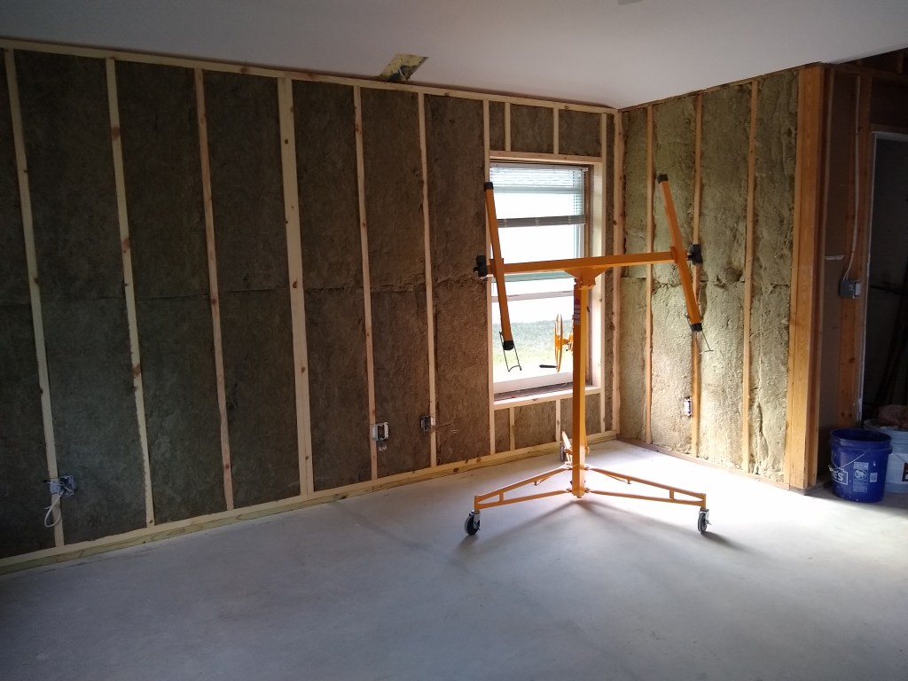
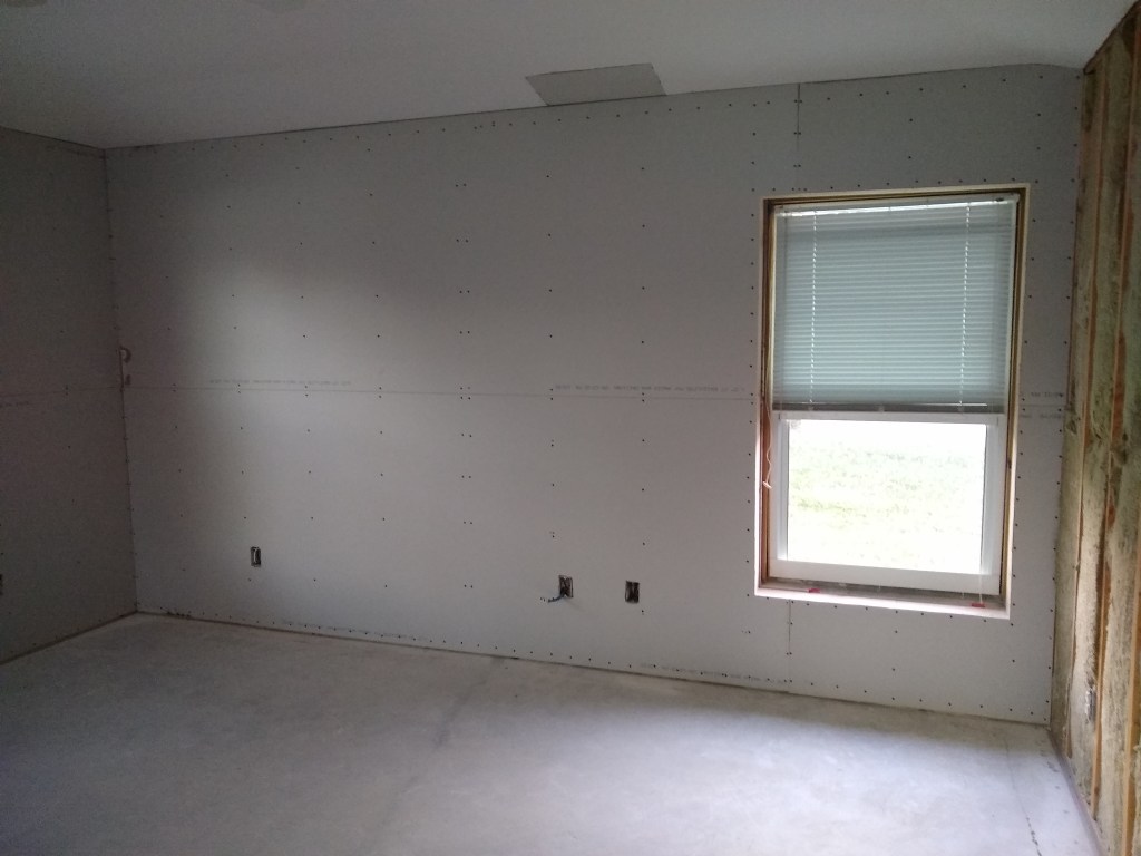
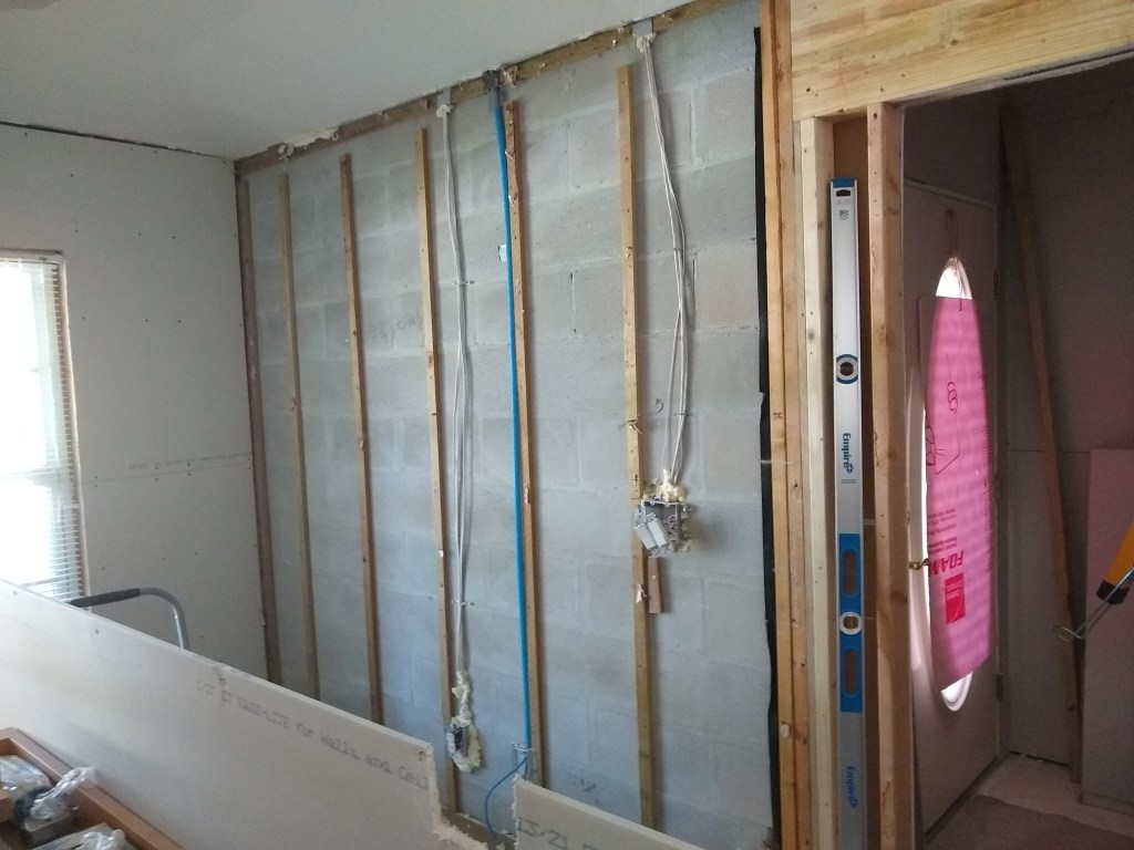
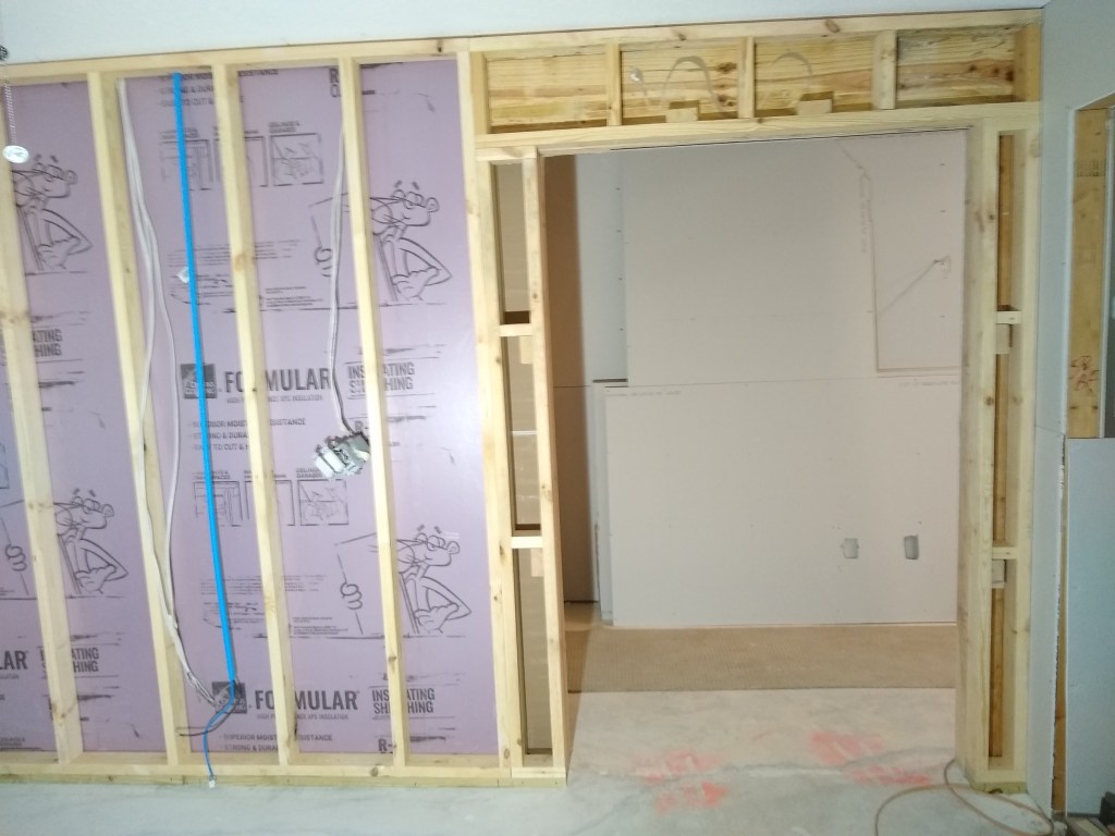
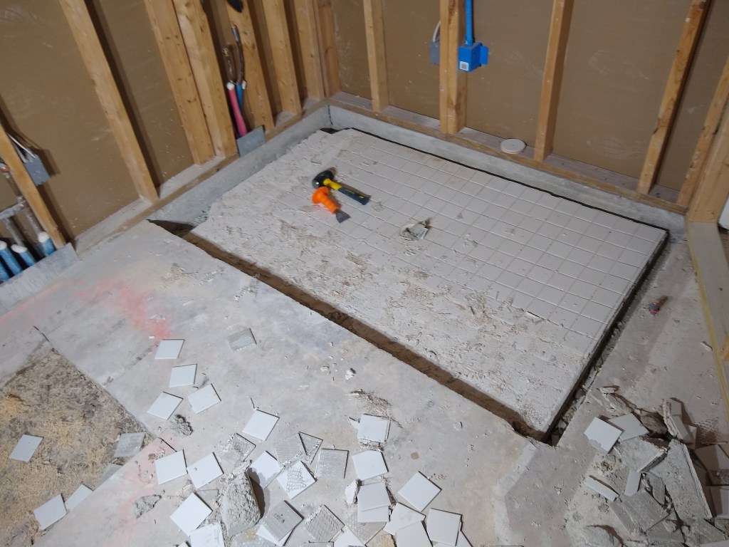
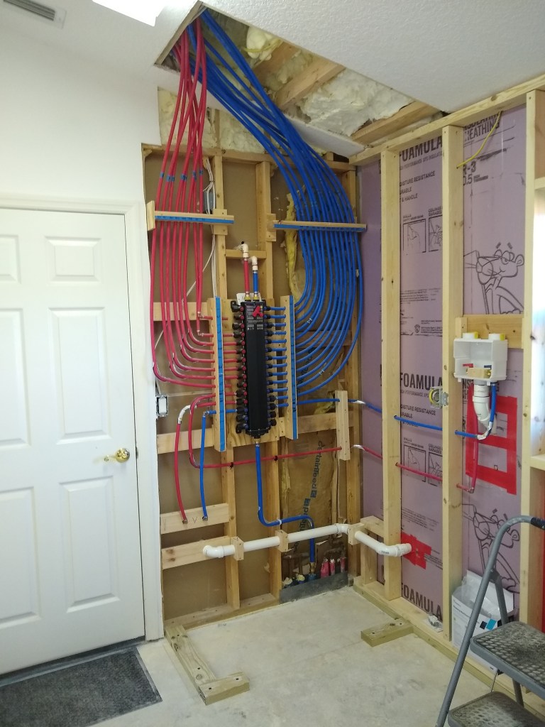
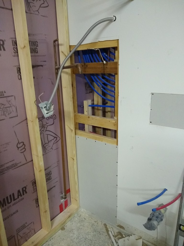
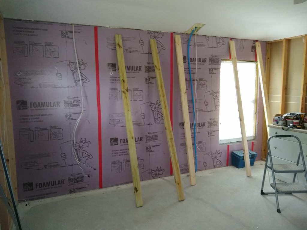
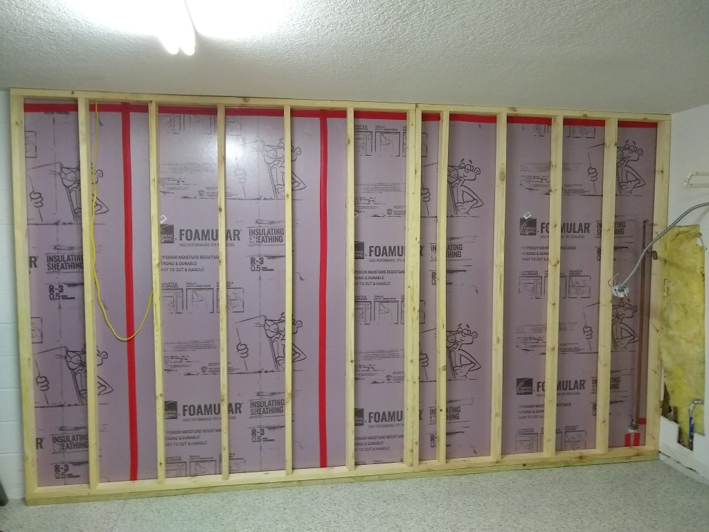
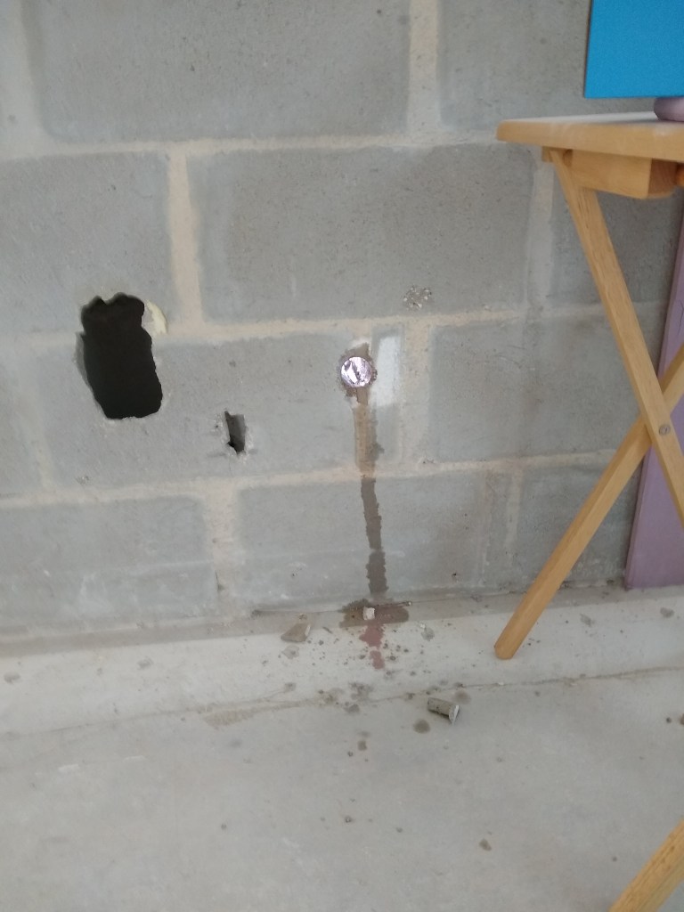
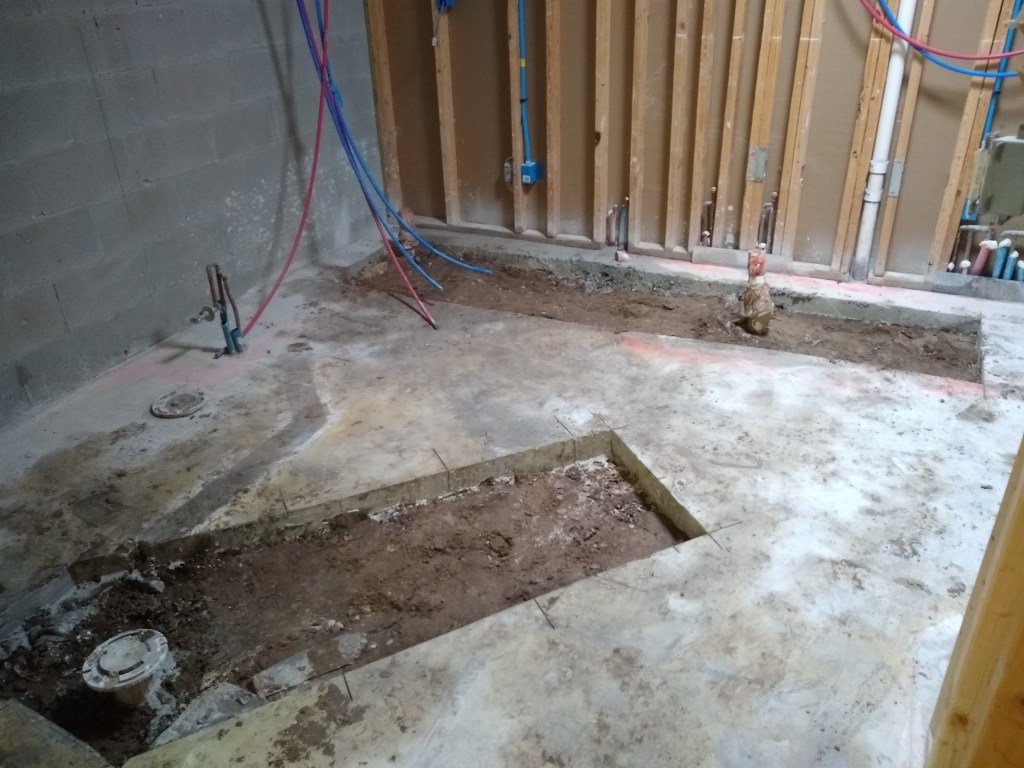
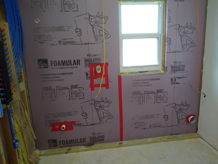
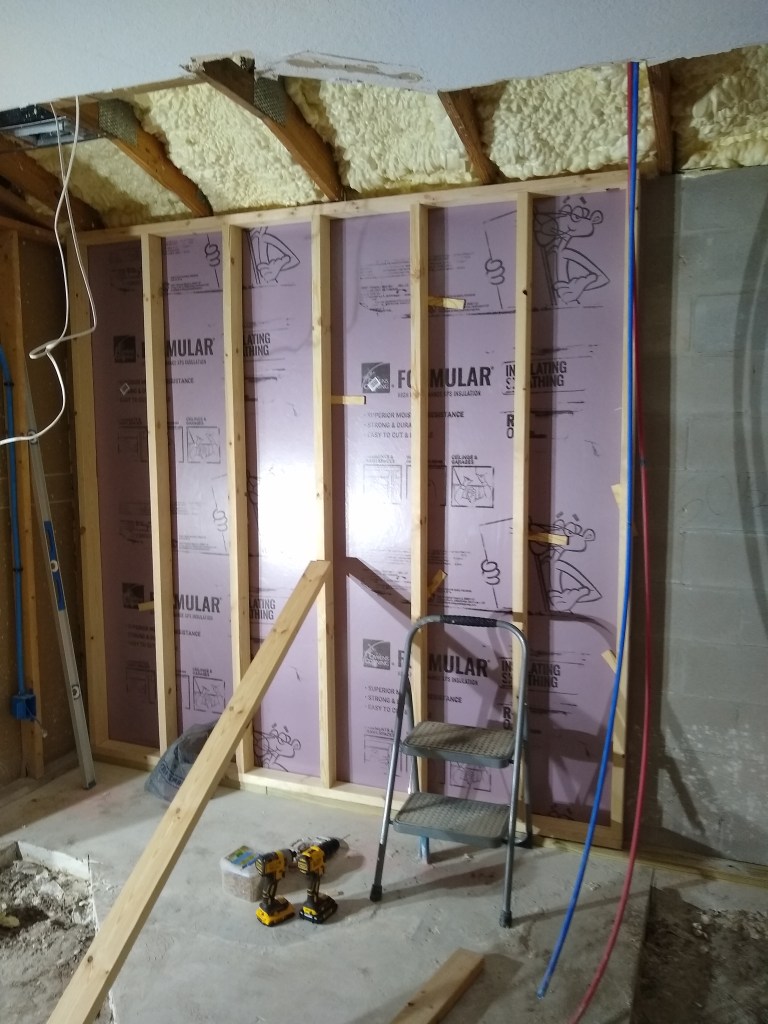
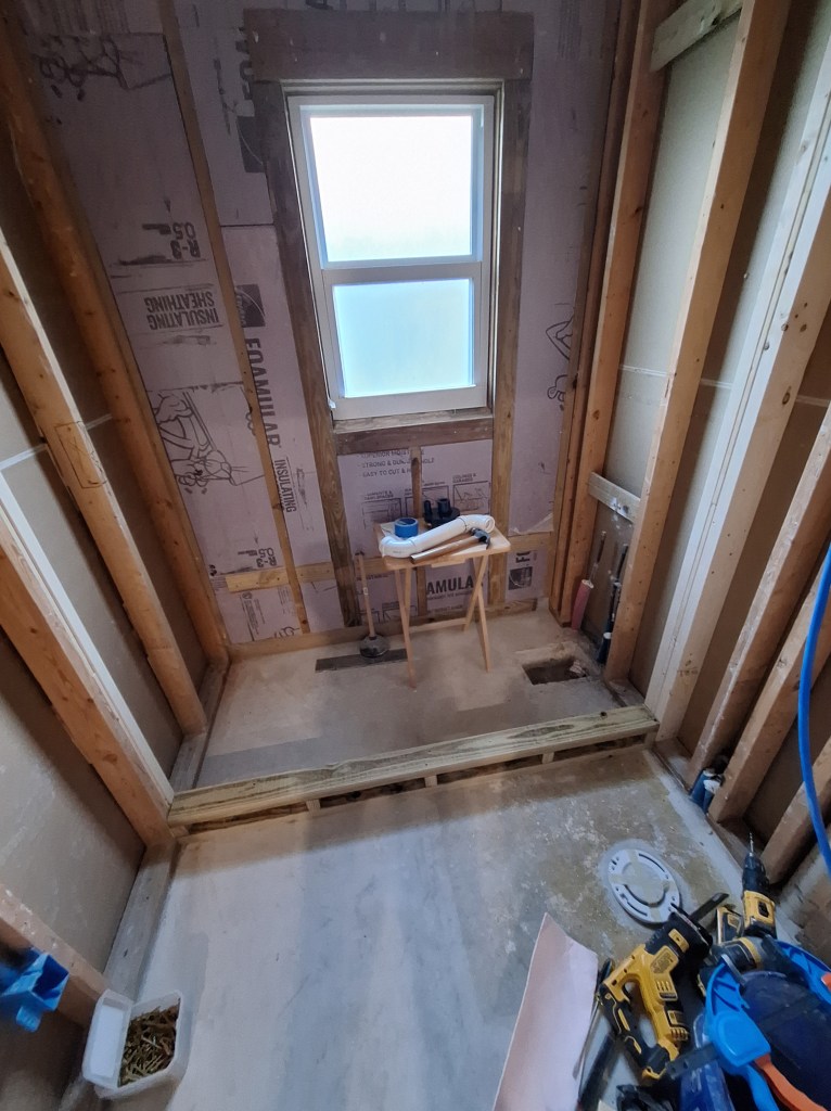
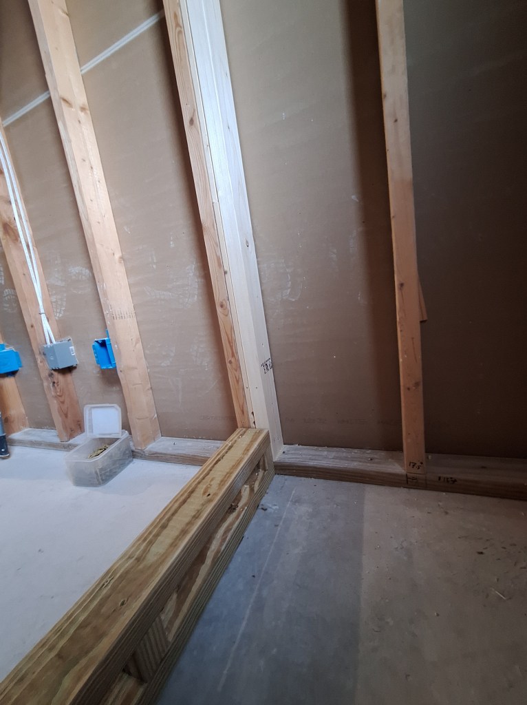
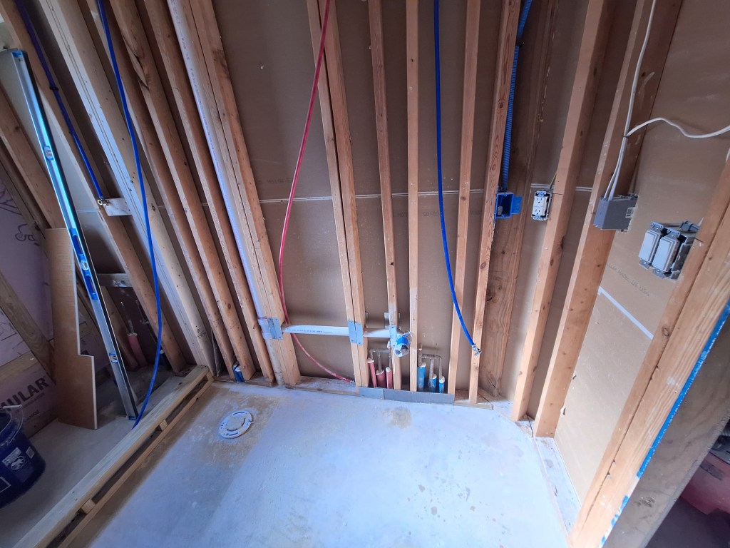
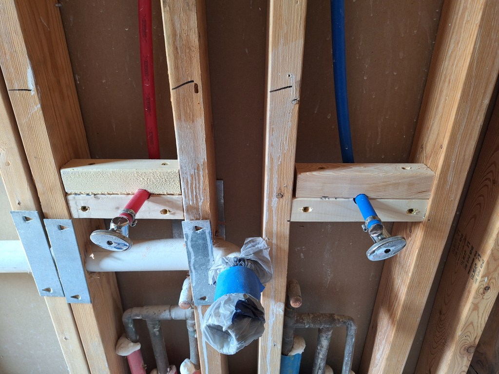
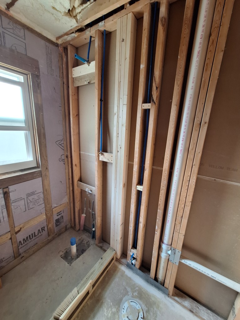
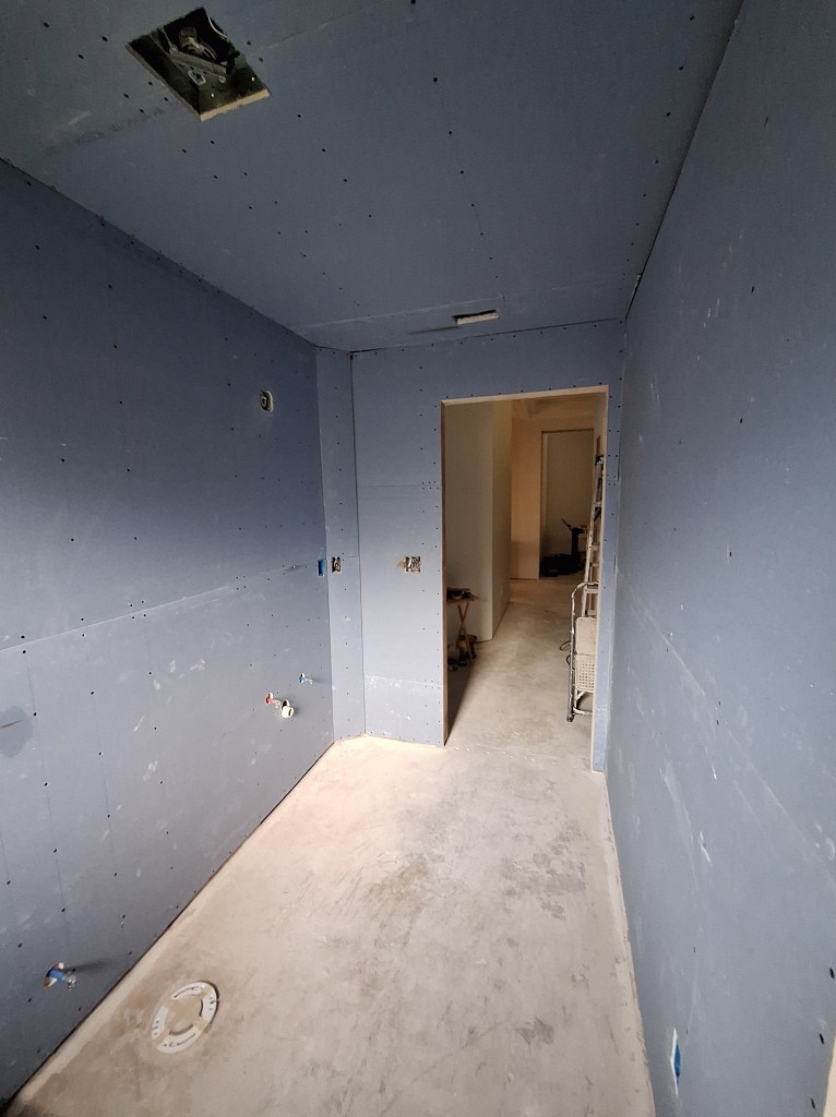
The first thing I did after cleaning out the space, was to relocate the shower supply lines. I put them in place back when I was running the PEX throughout the house, and simply placed them on the wall where the original pipes had been. You can see this on the left side of the image below.

Shower Pipes Original Location

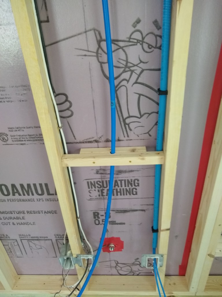
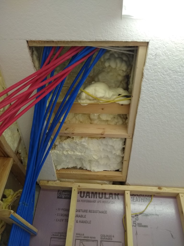
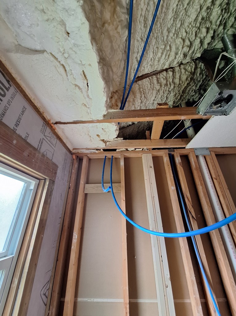
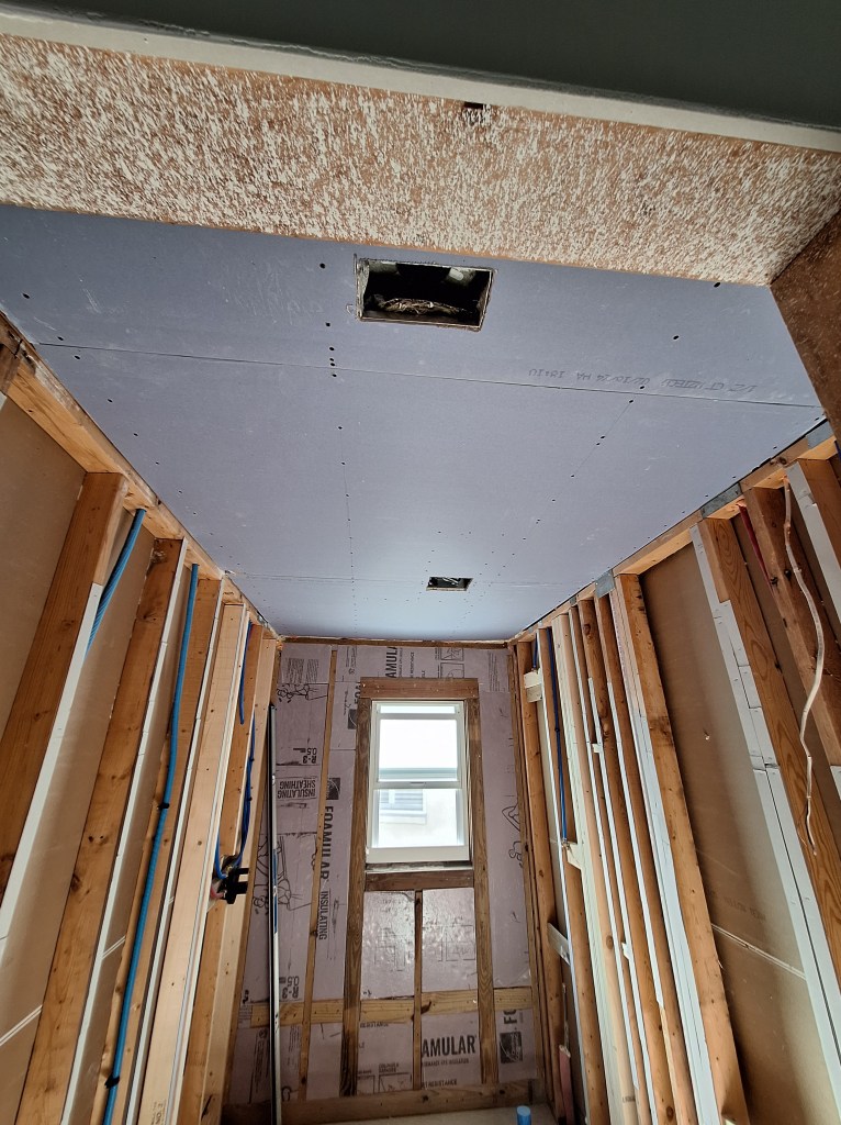
This bathroom originally had a bathtub/shower setup, so it made sense for the valve to be on that side of the wall. However, I no longer wanted a bathtub. All I wanted was a walk-in shower, with a curb. This meant that it made more sense to locate the valve, and therefore the supply lines, to the opposite wall, where you could set the temperature without having to be in the shower. To accommodate that, I pulled down some of the ceiling.

Making Room to Reroute the Shower Supply Lines.

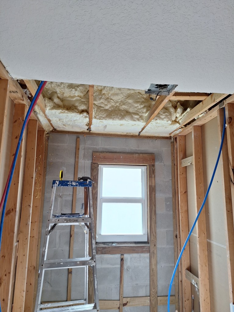
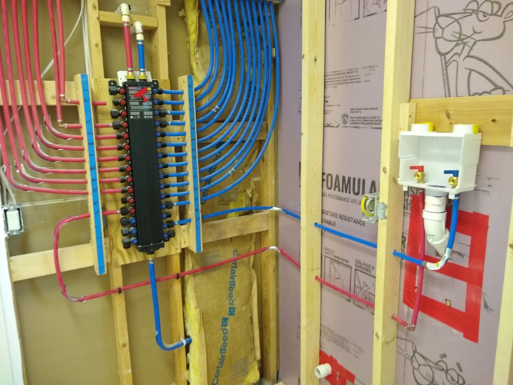
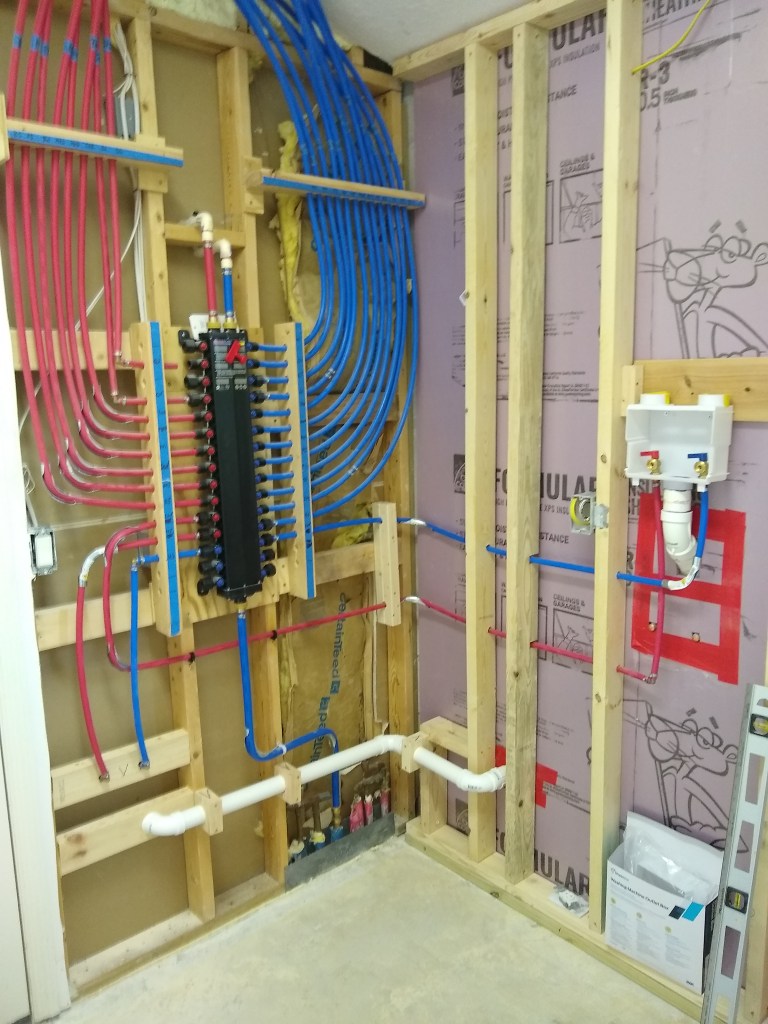
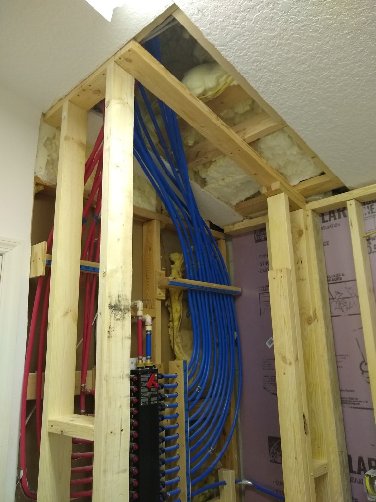
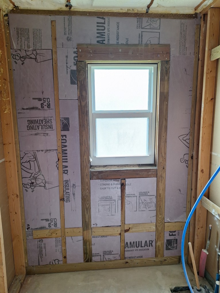
As you can see, there is a lot of spray foam up there, leaving little room to maneuver the PEX pipes. Opening up this area made this much easier, and I didn’t have to climb up into the attic to do it. In the image above, you can see the two supply lines dangling down from the ceiling on the left, which is the south wall. They will be fed down through the top plate of that wall once the framing work is done and I know where I will be placing the valve. But before that, I placed some foam board insulation against the exposed concrete blocks.

Foam board Added

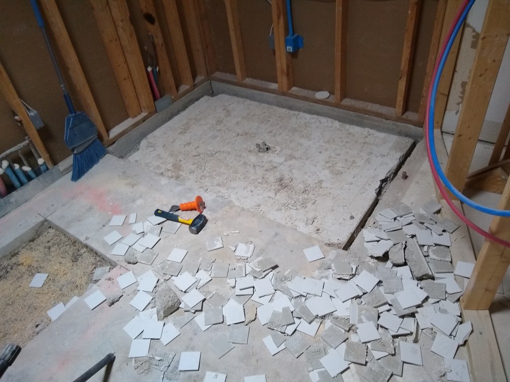
Next, I removed the toilet in order to get greater access to the shower area. It was a bit sad to remove the toilet because it worked flawlessly for so long. It had been my only working toilet since I started this renovation and it always just worked. I never even had to change the flapper.

Original Toilet Removed

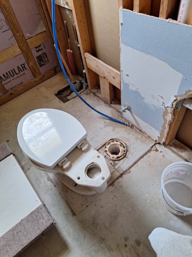
With the toilet no longer in place I removed the last of the drywall and tile that that surrounded it.

Tile and Drywall Removed

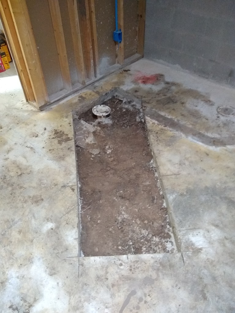
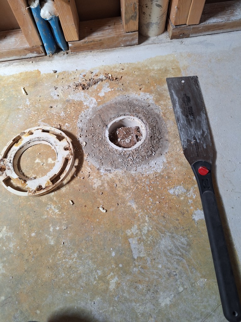
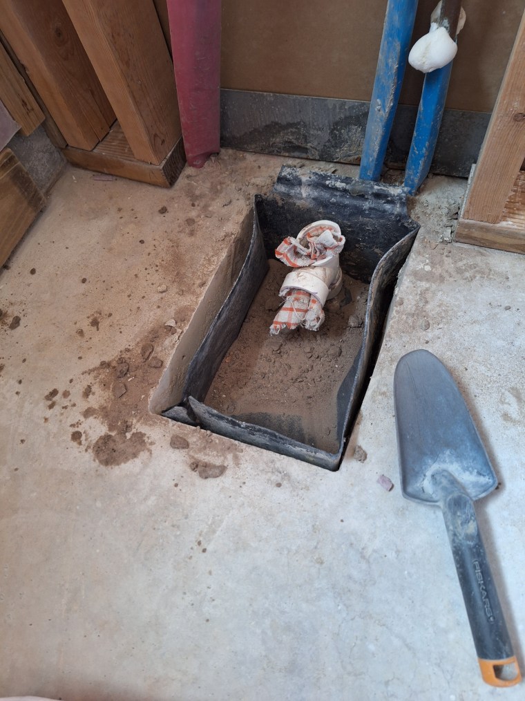
The original toilet flange held up well. It was set in place more than twenty years ago. It will be replaced.

Original Toilet Flange

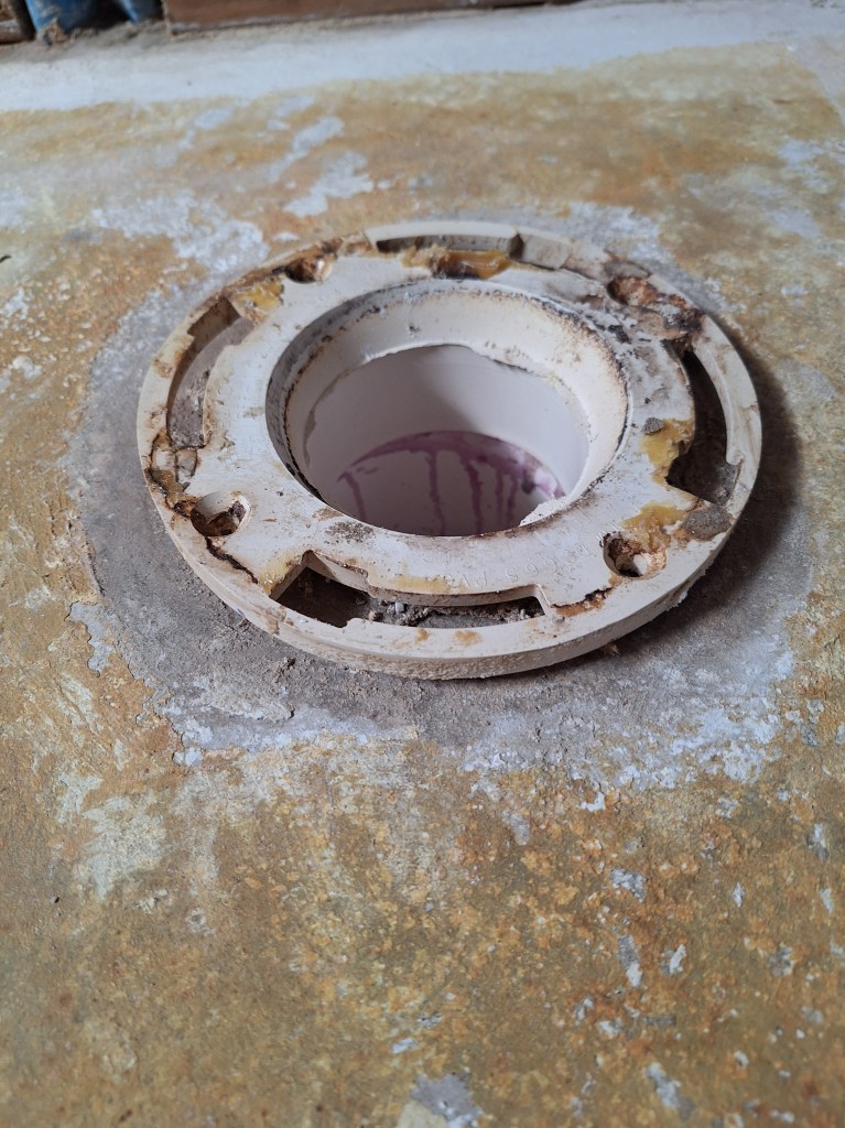
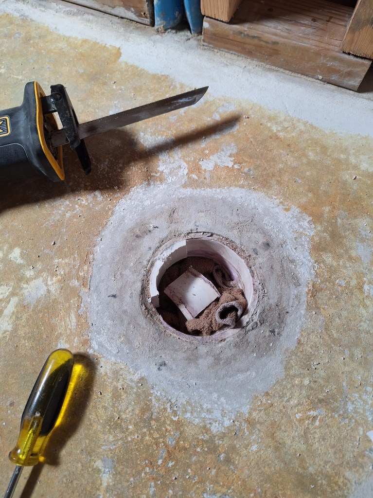
I removed the toilet flange using a pull saw. This worked extremely well, leaving the flange barrel flush with the floor. I stuffed a towel down the drain to prevent any debris from falling in.

Cutting Off the Flange
Flange Cut Off

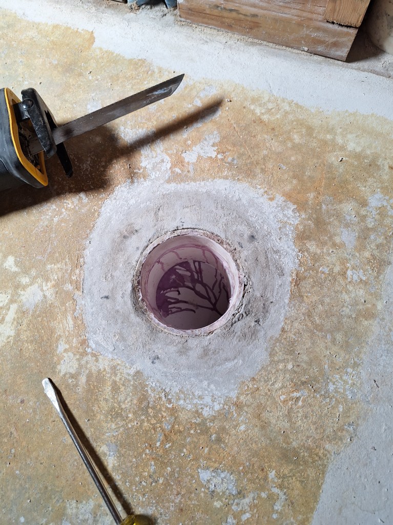
The barrel of the flange was removed by using my reciprocating saw to make vertical cuts, being careful not to cut into the drain to which it was glued, then chipping it out using a screwdriver. This was much easier than I expected. The pieces broke away easily.

Removing Flange Barrel
Flange Barrel Removed

With the toilet removed, I had room to install the shower curb.

Shower Curb Installed

This being a much smaller bathroom than the master bathroom, a curb makes sense here to contain the water. In anticipation of the glass wall and door that will enclose the shower, I added additional framing on either end of the curb.

Curb and additional Framing – South Wall
Curb and additional Framing – North Wall

The curb is made from pressure treated lumber. Since it will be covered in a water proofing material, only the wood touching the concrete floor needed to be pressure treated, but I chose to make the entire thing from the same material. To the right in the shot above, you can also see that I temporarily covered the toilet drain with a flange and plug to make sure nothing falls into it. This flange will not be the one I use in the end, because it is too small, but it serves as a protective cover for now.

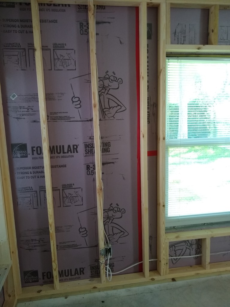
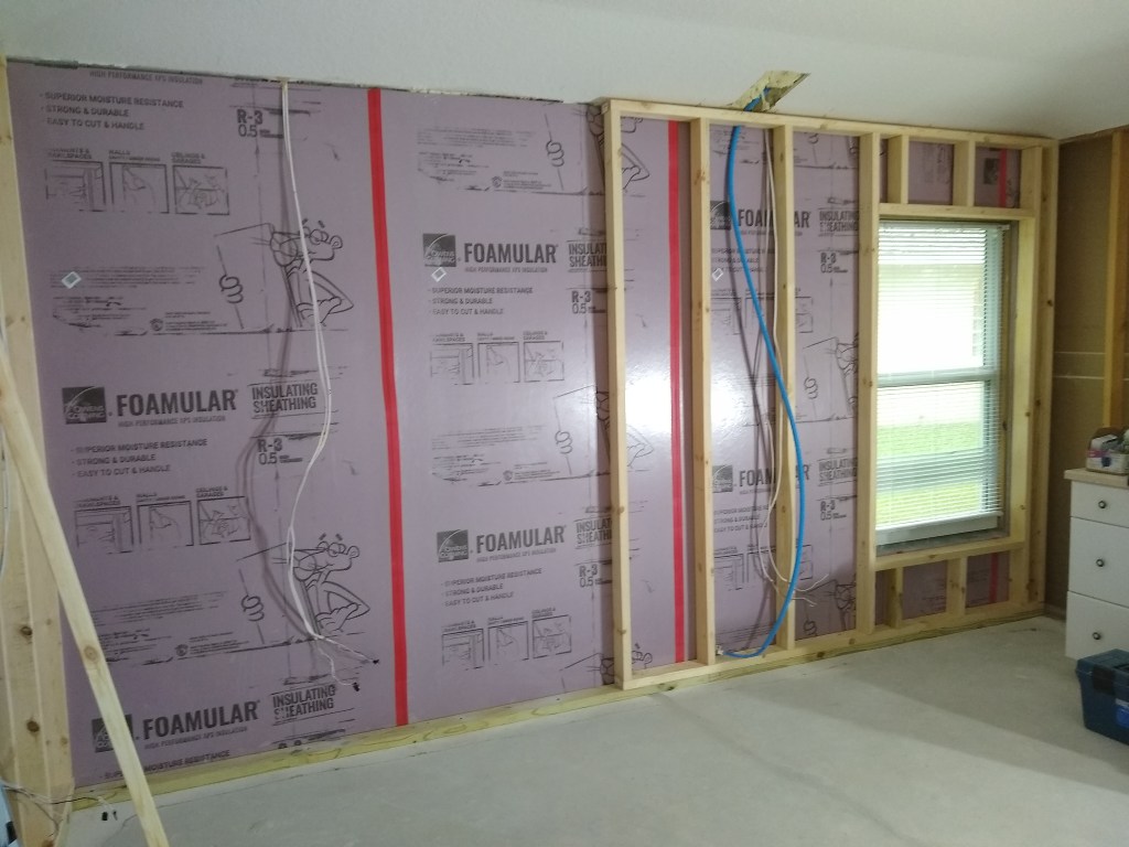
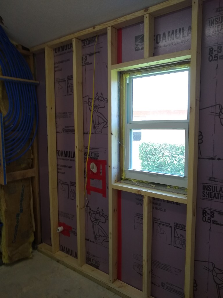
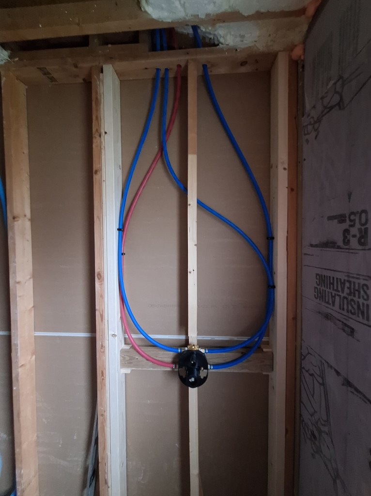
Next, I installed the shower valve.

Shower Valve Installed

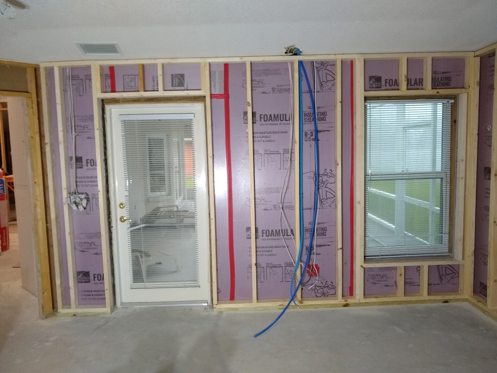
As you can see, in order to position the valve centrally on that wall, I had to cut a notch in the center stud to make room for it. I also added another stud along the outside wall in order to provide more area to attach the waterproofing board (Kerdi Board).

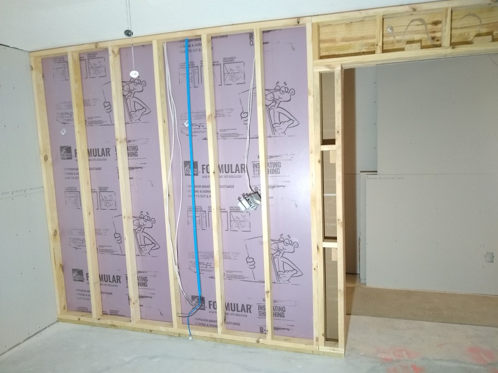
I brought the hot and cold supply lines down through the top plate, but it was extremely tight, especially for the cold line (blue). The two lines that leave the valve and travel overhead to the opposite wall would have to be done in a more round about way.

Supply Lines to the Valve
Supply Lines from Valve to Shower Head and Hand Held Wand

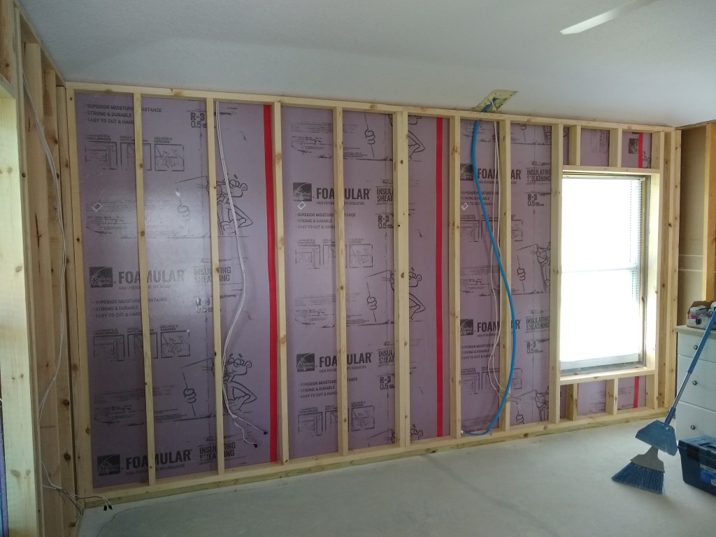
Given the tight spacing, I had no choice but to run the two traveler pipes to the valve as shown below.

Supply Lines Connected to Valve

I also made a change to how I brought down the two travelers to the drop ear elbows.

Supply Lines Connected to Drop Ear Elbows

If you look a couple of pics up, you’ll notice that I originally ran the two lines down the preexisting holes in the top plate. After deciding where to place the blocking for the shower head and hand held wand, I moved them to more directly align.

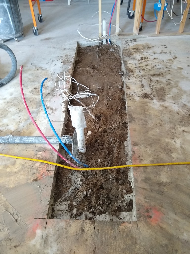
With the supply lines in position, I started looking at the drain situation. Since there was a tub/shower in place before, the drain needed to be replaced with one suitable for the shower, which meant pulling out the existing 1-1/2″ drain and installing a 2″ drain, as required by code.

Existing Drain for Shower/Tub

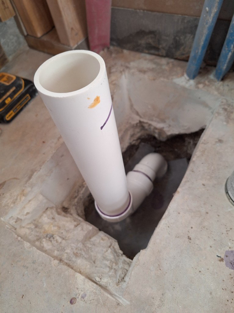
Below you can see how the fitting I just removed has an inlet for the drain and another for the overflow drain of the tub. The remaining stub goes down about 12″ to the bottom of the p-trap.

Tub Drain After Removal

Below I show the new arrangement that will tie into the remaining stub.

Drain Fittings Dry Fit

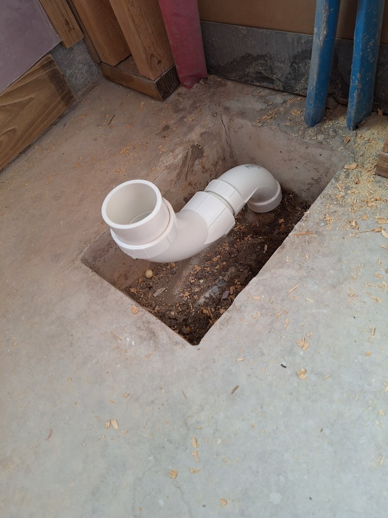
As you can see, it sits way too high. This is made even more clear when the drain itself is added.

Drain Dry Fit

Even after the shower pan is added, I would still have to lower the stub by close to 8″ to accommodate this, which meant cutting out the concrete at the bottom of the box. It also appeared that once the drain flange was added and this whole assembly was lowered, it would come into contact with the front of the box. So the front edge of the box would have to be chipped a way a bit to make room for it.

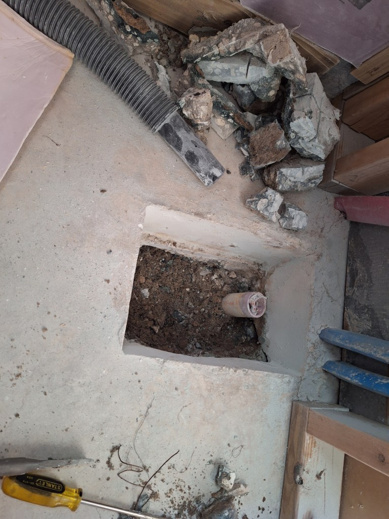
I began by using my angle grinder to score a series of lines as deep as it would manage. After that, I used my small jackhammer, and the pieces broke away quite easily.

Cutting Away the Concrete

I continued in this way until I had cleared away everything around the existing 1-1/2″ riser pipe.

Concrete around Pipe Removed

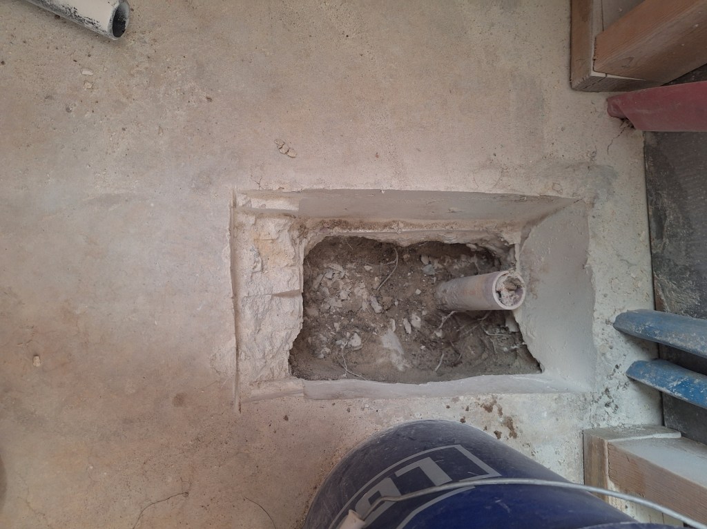
Next I removed the dirt from around the pipe until I reached where it connected to the p-trap. I wanted to go as low as possible and still have something to connect to. Once the dirt was removed, I placed the dry fitted assembly roughly in position to determine if I needed to expand the front edge to accommodate the drain flange. As expected, I did have to expand it, so I chipped away only enough to make room for the flange.

Making room for the Drain Flange

After that, I used my inside pipe cutter to remove all but an inch or two of pipe above the p-trap fitting then added a long sweep 90 degree fitting.

First 90 degree Fitting Installed

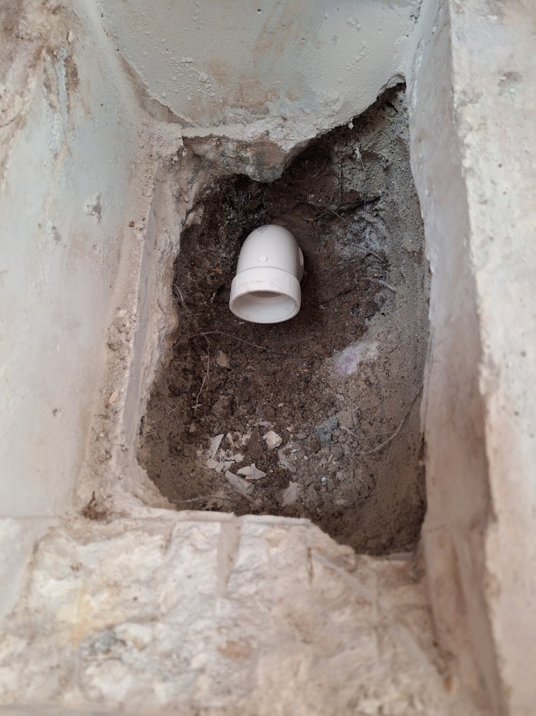
Then the remaining pipes could be added, which included a short 1-1/2″ connector to a reducer bushing that would fit into another long sweep 90, but this time with a diameter of 2″, as required.

Transition from 1-1/2″ to 2″.
Drain Pipes in Position

I kept the 2″ riser long so it can be cut to final height after the shower pan is in place, just like I did in the master shower. Once given the okay from the inspector, this area will be ready for a concrete pour to lock it in place.

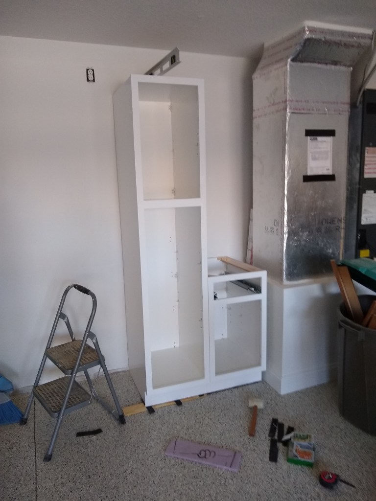
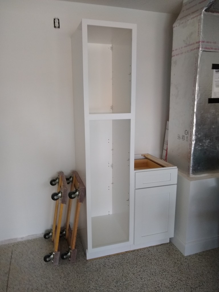
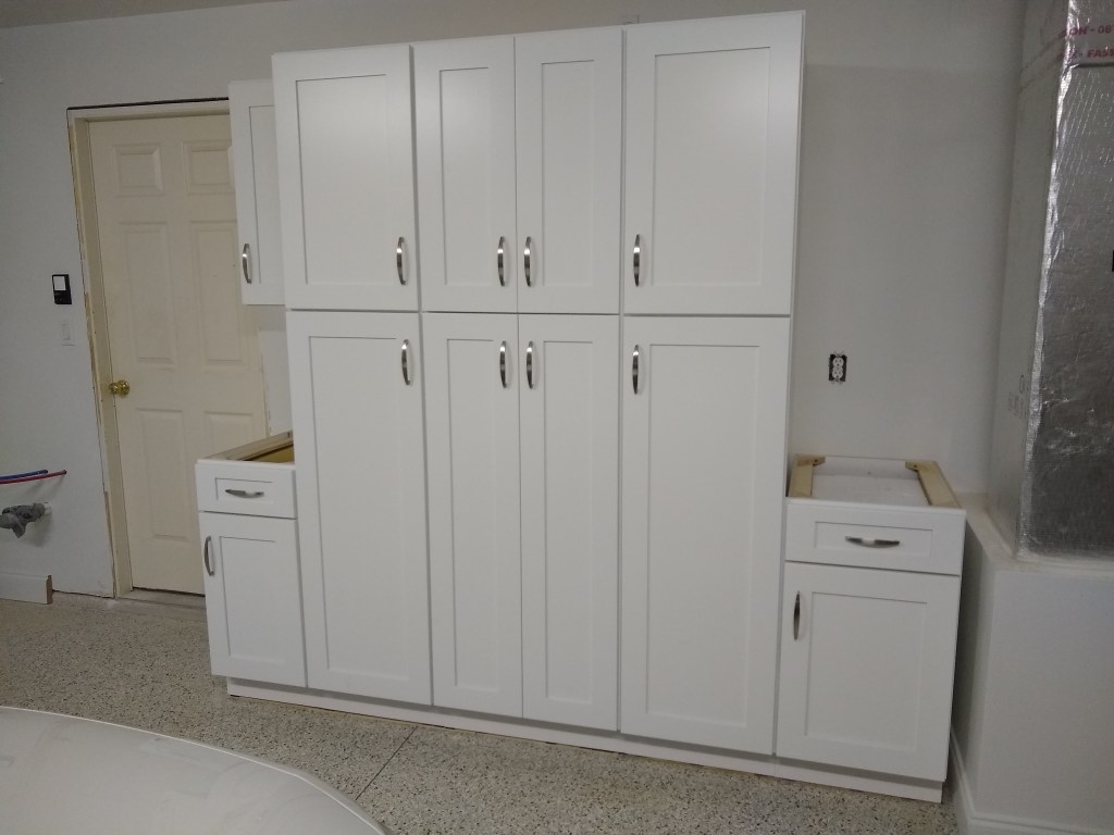
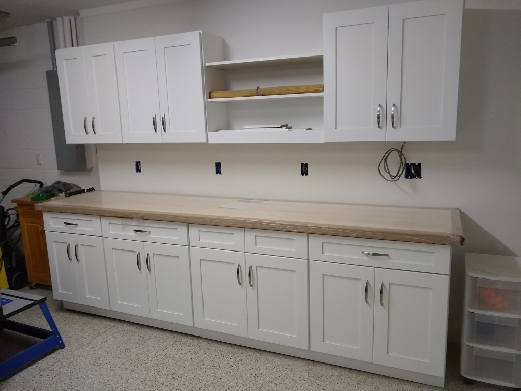
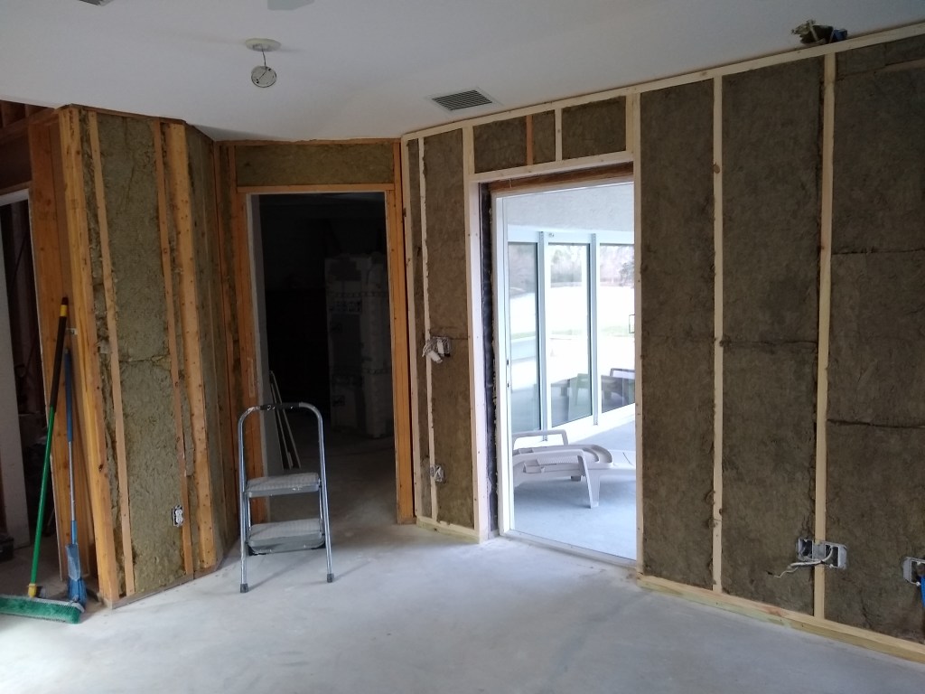
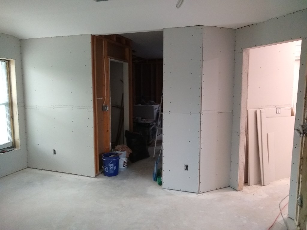
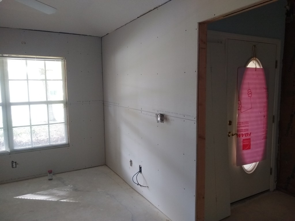
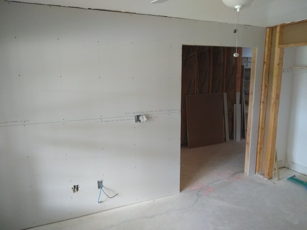
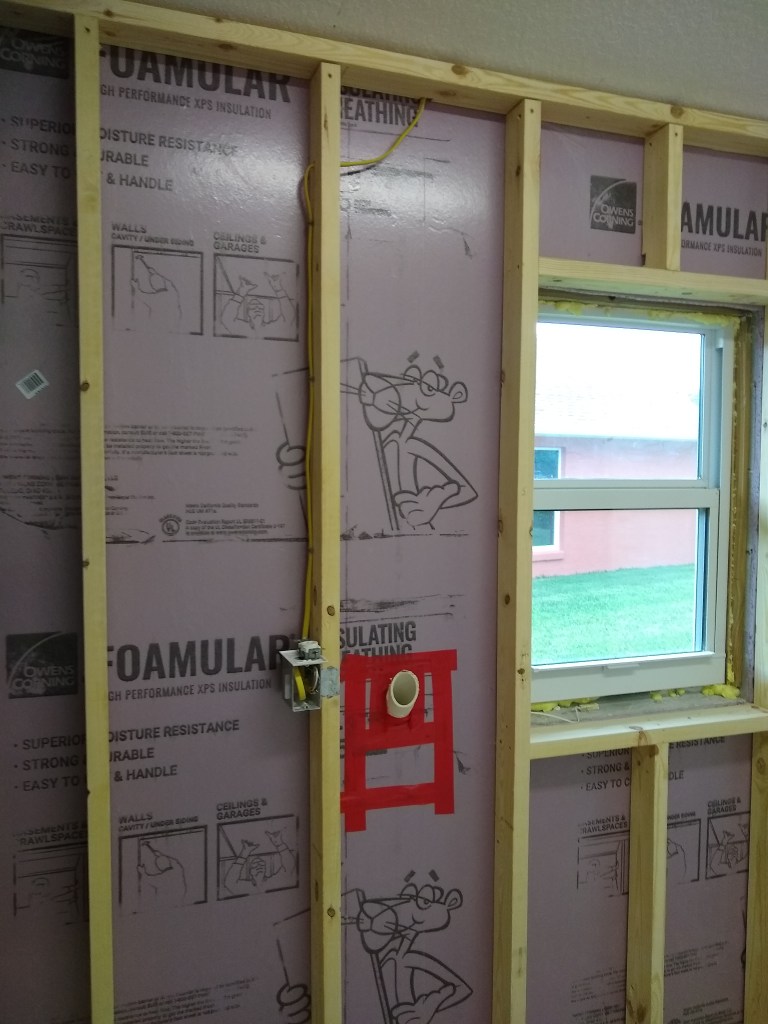
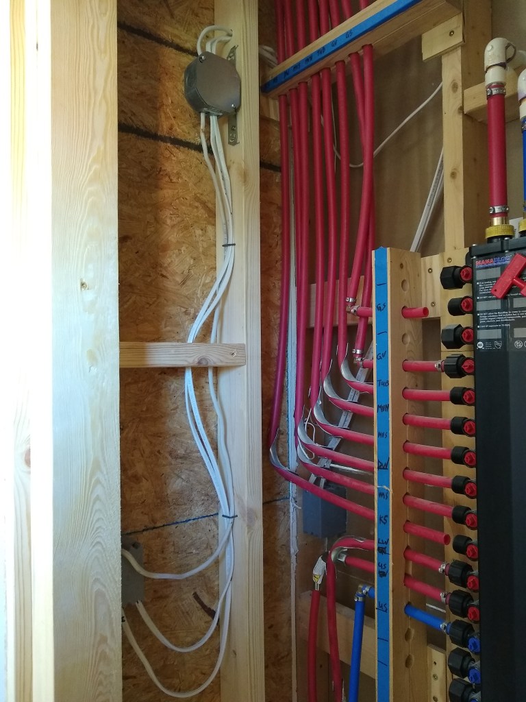
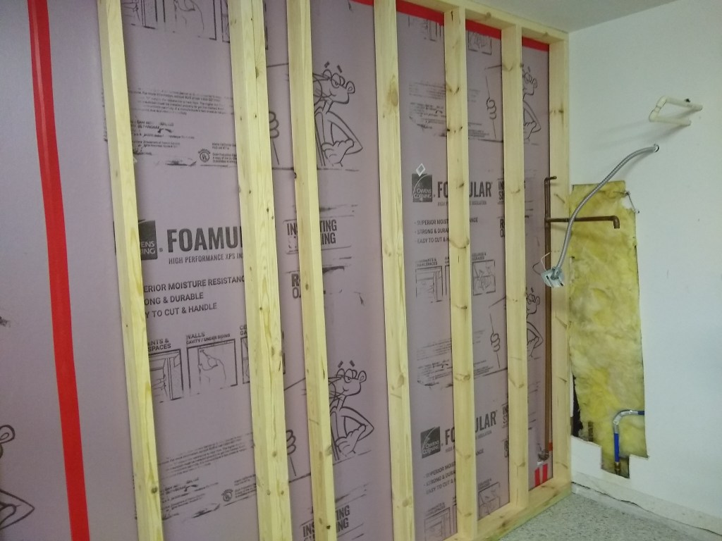
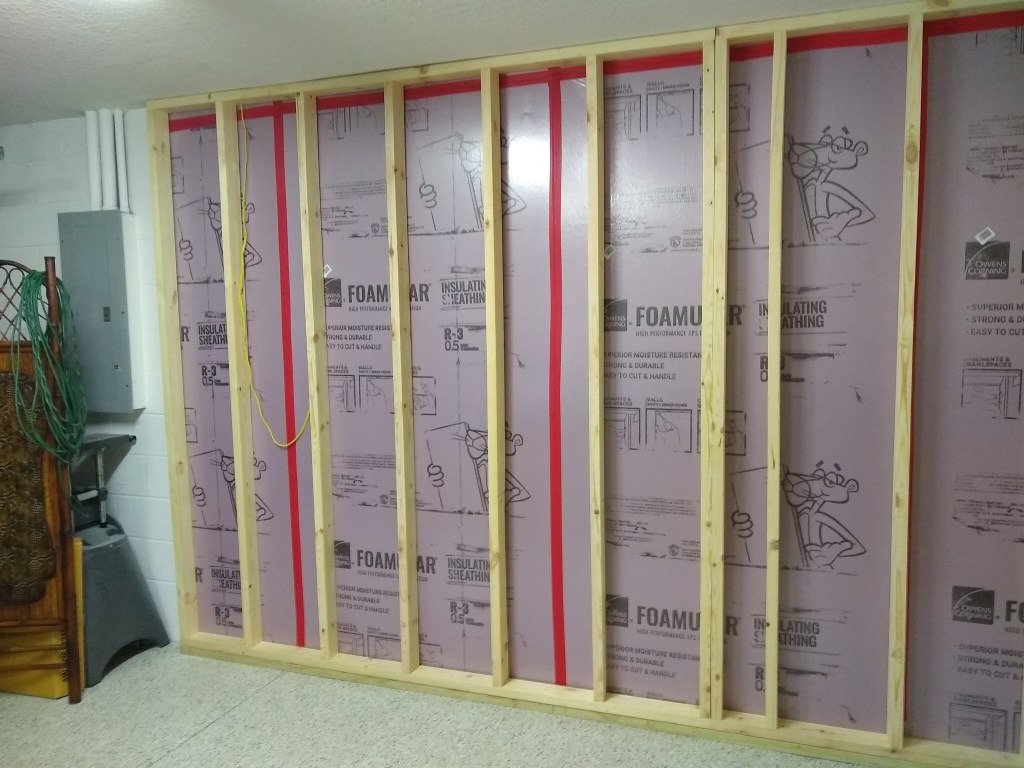
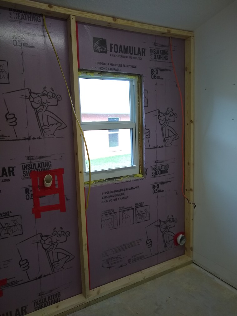
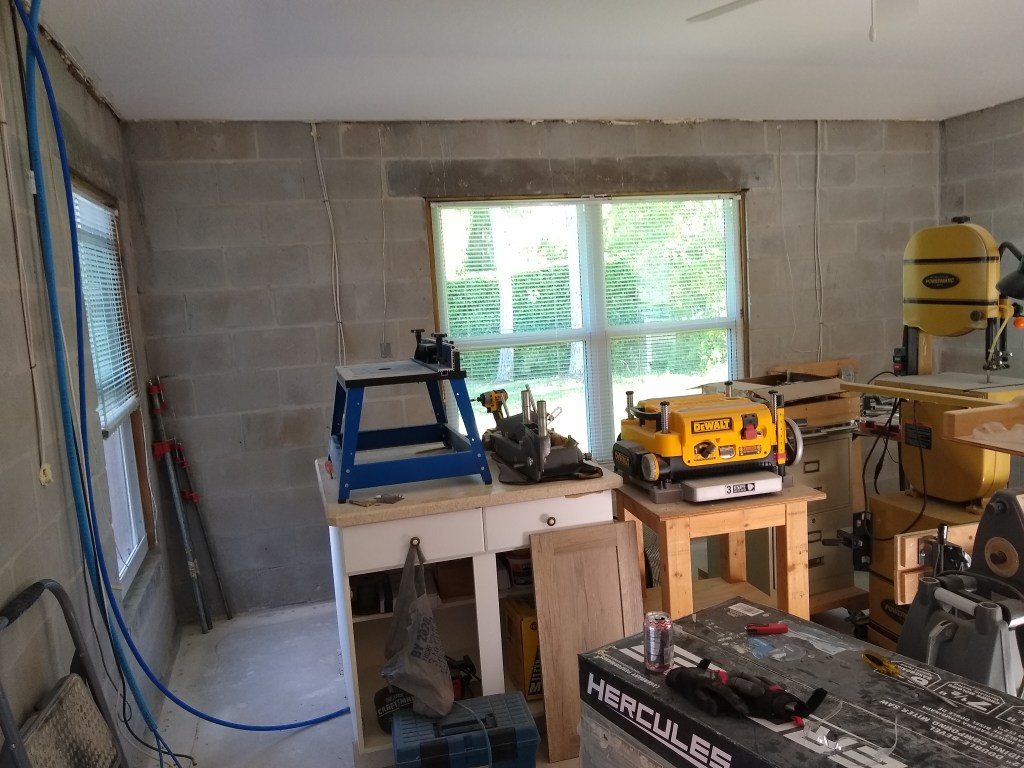
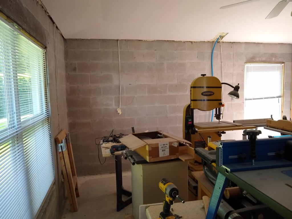
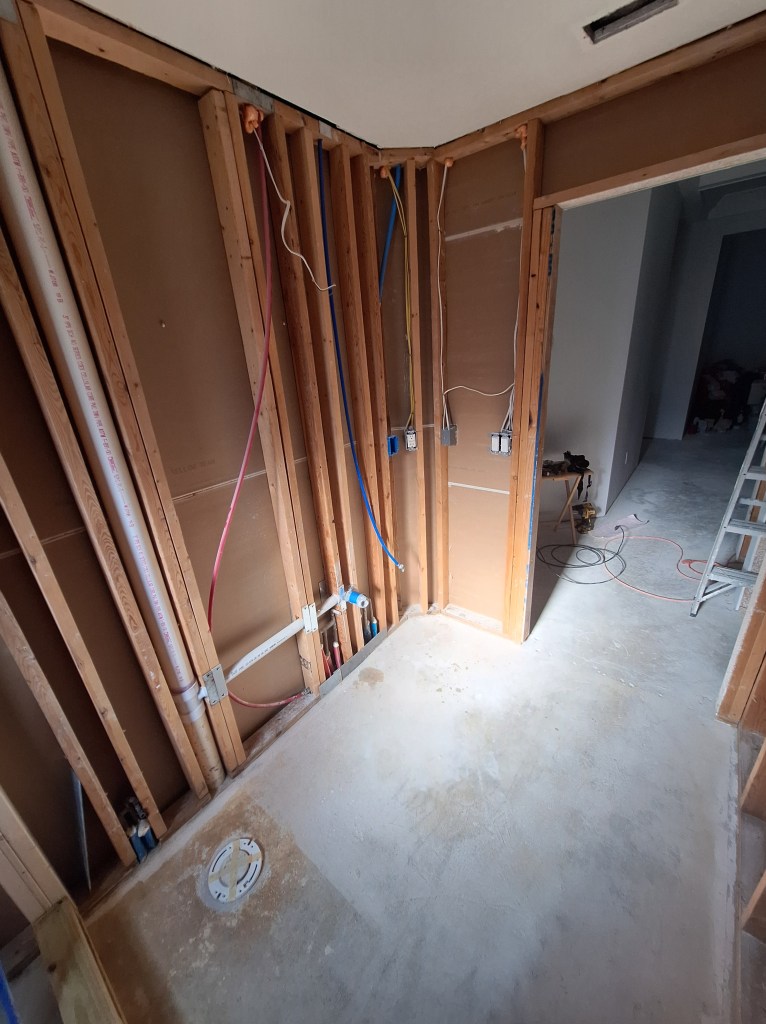
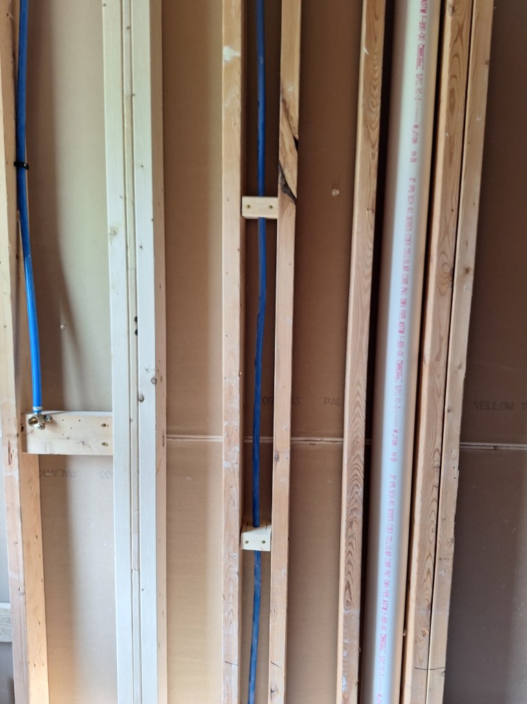
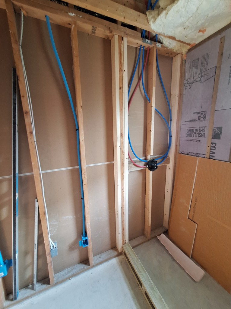
Reluctantly, I removed the utility sink. I had intended to keep it in place as long as possible, but now I was ready to check the walls for flatness and add shims where needed, and the utility sink was in the way. Also, I was ready to schedule a plumbing rough-in inspection, so I needed it out of the way so the inspector could see the drain situation behind the sink. Here are a couple of shots after I removed the sink.

Utility Sink Removed

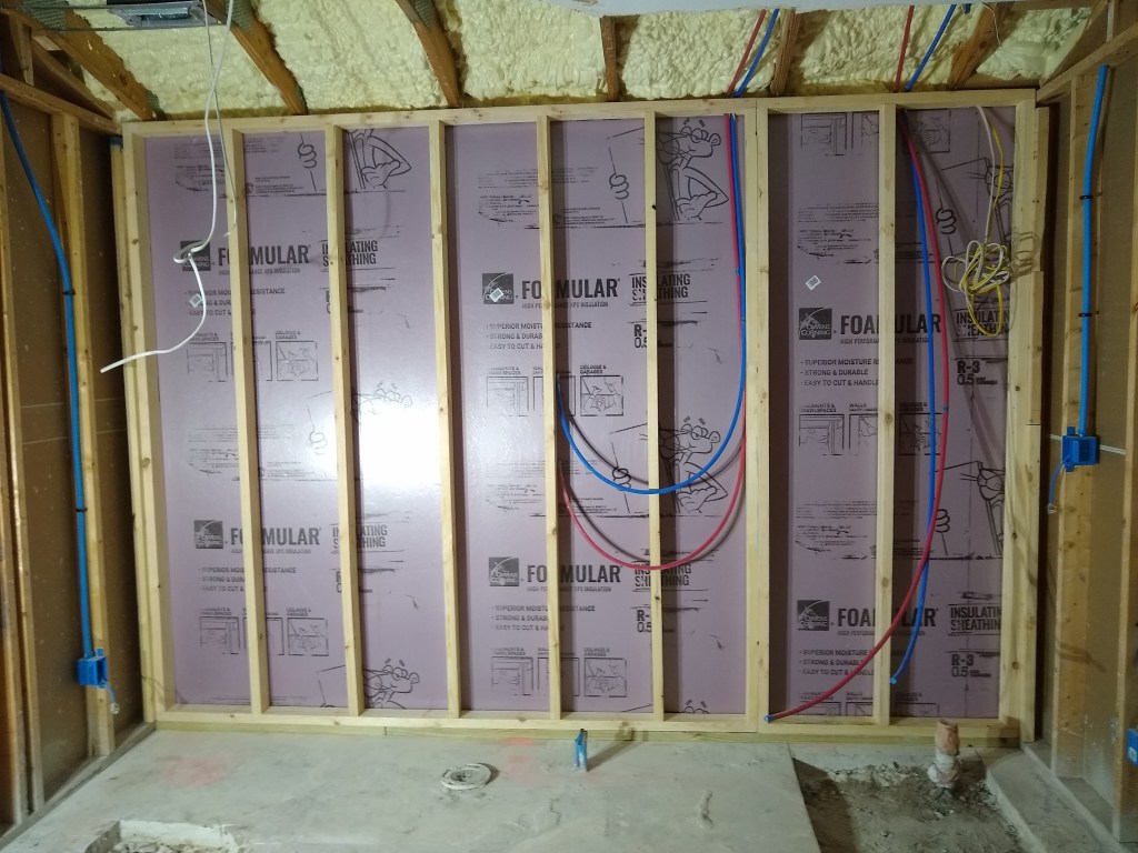
With the area cleared, I began securing the supply lines. I used plastic clips to secure them to the studs.

Vanity Supply Lines Secured

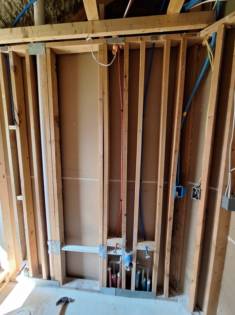
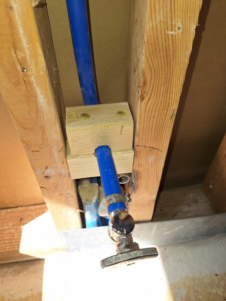
Where they emerge from the wall cavity I added a 90 degree PEX fitting (hidden behind the wooden clamps) and secured them with homemade clamps. These worked very well and allowed me to position them between the studs where I want.

Homemade Clamps for Vanity Supply Lines

Due to the limited space between the studs where the toilet supply line ran, I could not use the plastic clips to secure the PEX pipe, so I made my own, as you can see below.

Homemade Clamps for Toilet Supply Line
Toilet Supply Line Emerging from between Studs

With that done, the inspector came by and approved my work, meaning I was now free to cover it all up. For the ceiling and walls, this would mean putting up drywall. For the shower, this would mean Kerdi board. It also meant I could fill in the shower drain pipes with concrete. In preparation for that I added back the dirt I removed and added some TapCon screws to serve as mini rebar (as suggested by the inspector).

Drain Pipes ready for Concrete

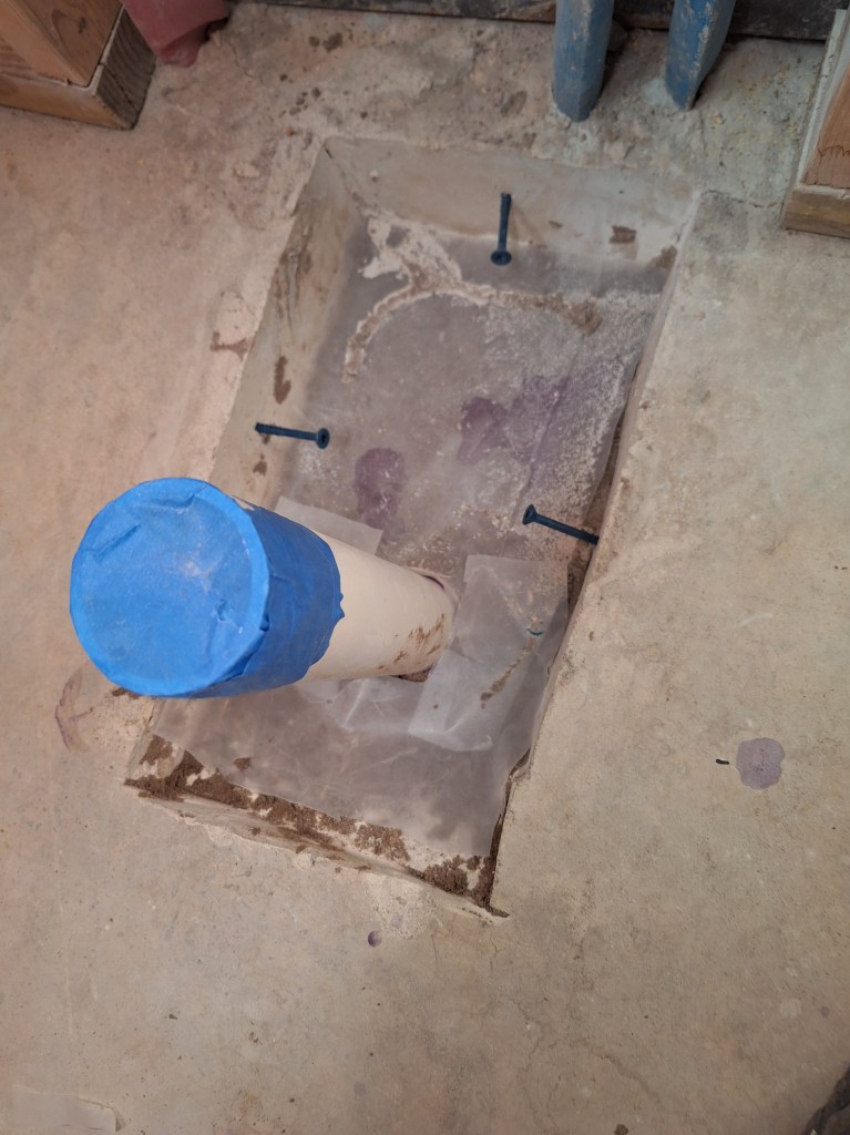
Since the area around the drain pipes is quite small, no rebar is really needed, but adding a few screws only took a few minutes, so why not? Later in the process I poured concrete to cover part of the opening. I left the area around the riser pipe open as the under side of the drain will need that space.

Concrete Poured

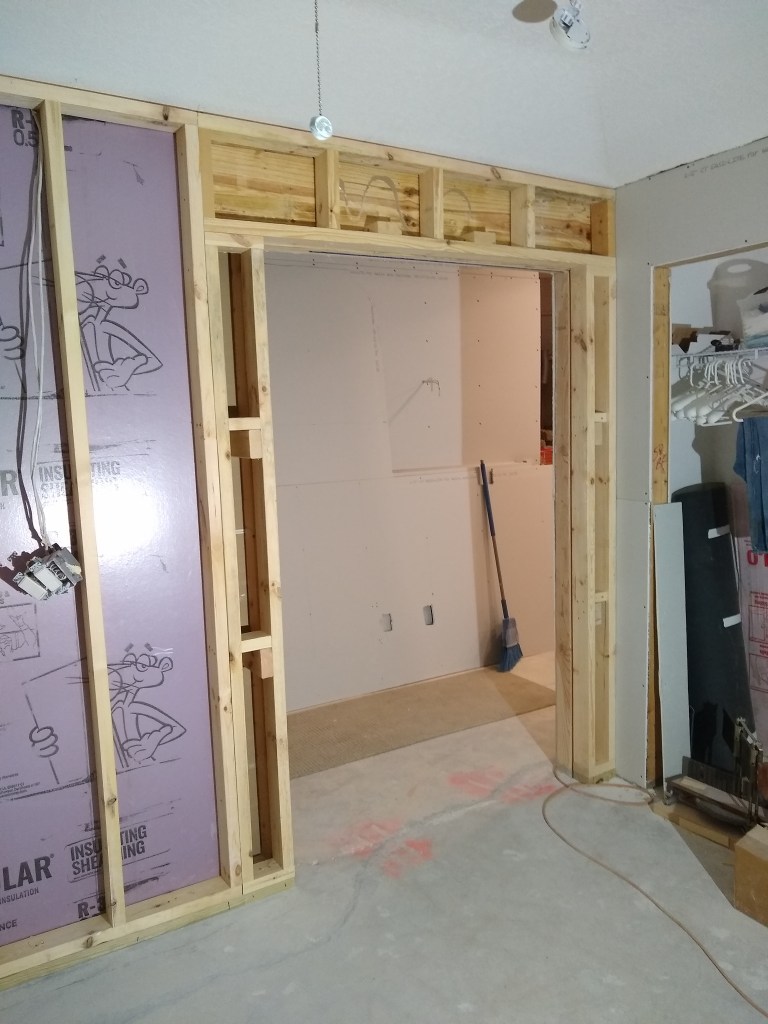
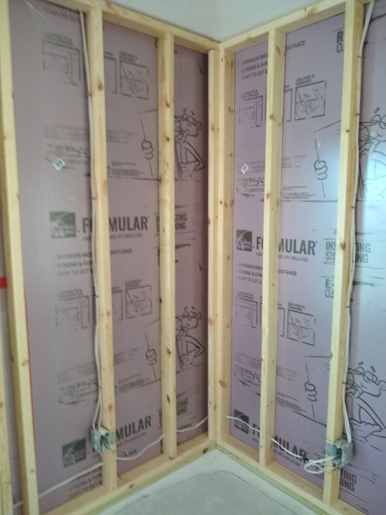
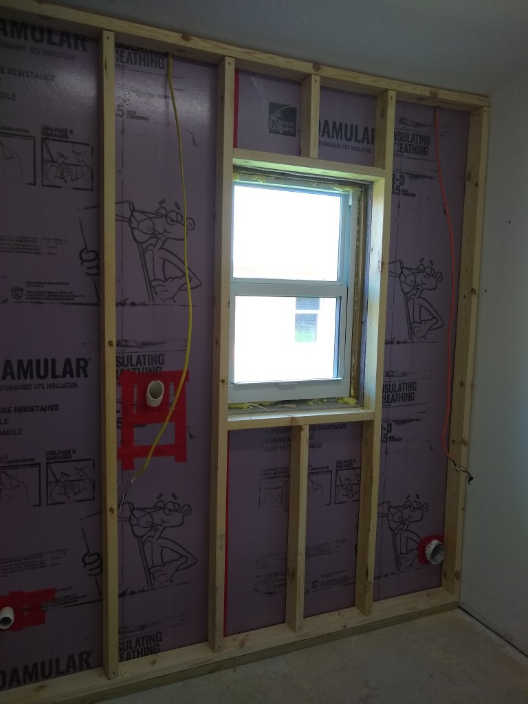
Before putting up drywall, I also wanted to add additional blocking where I thought it might be helpful. I added another stud to the outside of the shower curb to serve as a nailer.

Nailer added to North Wall outside of Curb
Nailer added to South Wall outside of Curb

These nailers were added because this will be the junction between the Kerdi board and the drywall, so I needed something for the edge of the adjoining drywall sheet to screw into. I also added an additional stud to the inside corner between the entrance wall and the vanity wall (shown below), which is angled at about 45 degrees. Originally there was nothing there for the drywall to attach to, which is probably fine given that it would receive no stress, but since the walls were open, I decided to add it to make the inside corner more secure. Notice how I had to notch it in order to make room for the Ethernet conduit.

Additional Stud added in Corner

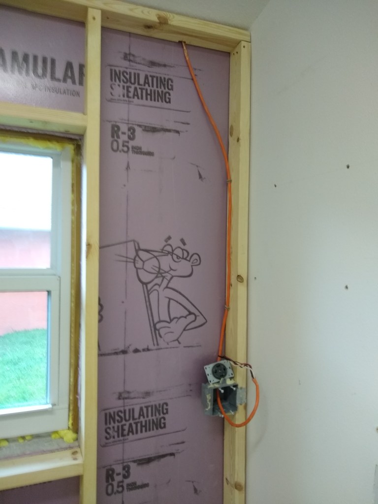
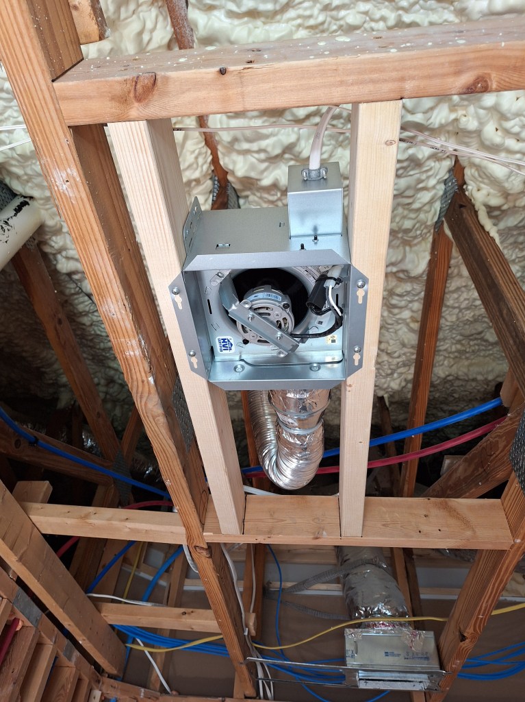
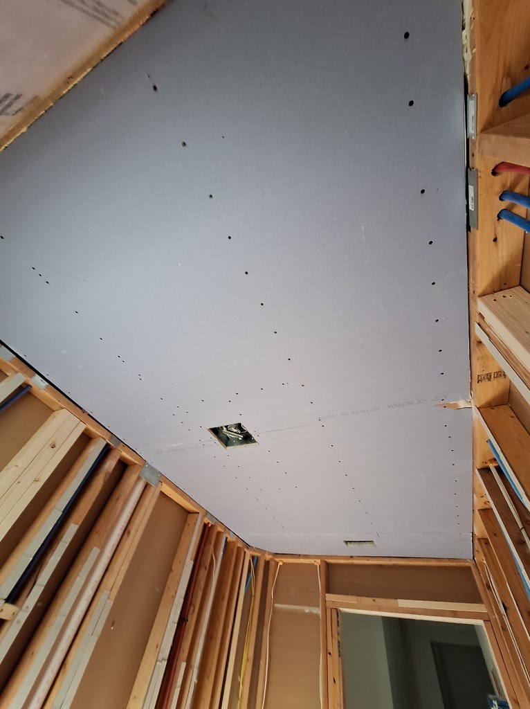
I decided I would replace the original vent fan with a new one that would also have a light. This meant I would have to replace the wiring to the fan from a 14/2 gauge to a 14/3 so that the vent and the light can be controlled by separate switches. As a result, I decided to pull down the remainder of the ceiling. You can actually see evidence of this in a couple of the shots above. With the ceiling opened up, I was able to create a custom opening for the new fan/light, as shown below.

Framing for new Vent Fan

One of the nice things about doing it yourself is that you have the ability to customize and even change your mind. Although this bathroom has a window in the shower area, I thought it would be a good idea to introduce a fan with a light so that you are not depending solely on the vanity light at night time.

Vent fan Installed

Since I didn’t have quite enough 14/3 wire to reach the fan housing, I had to splice two separate lengths together, which required a junction box.

Junction Box to extend wire to Fan housing.
Vent Fan Wiring Complete

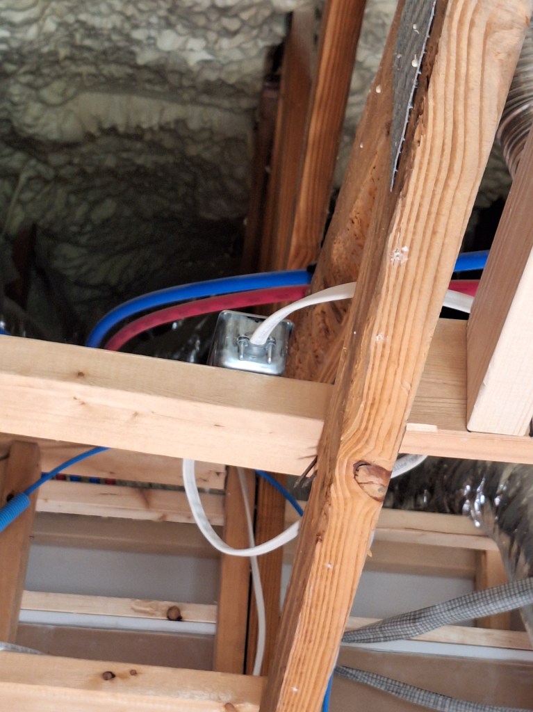
With no switches in place, I tested the fan and light by temporarily connecting the neutral and ground wires and then manually bringing the hot wire in contact with the wire to the fan and then to the wire for the light.

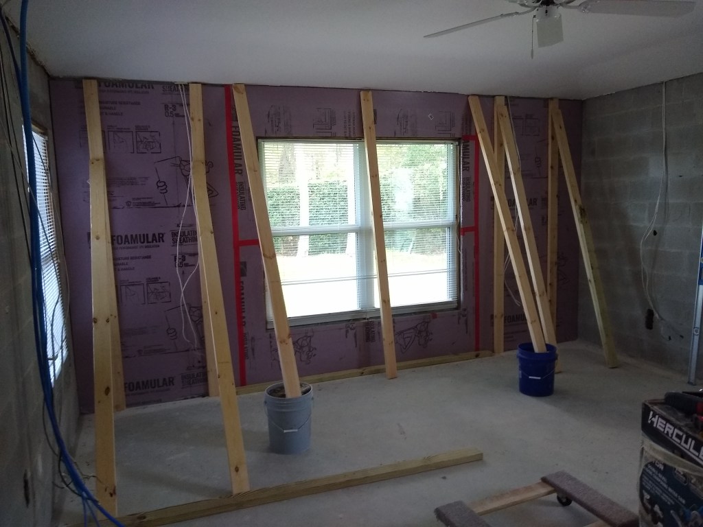
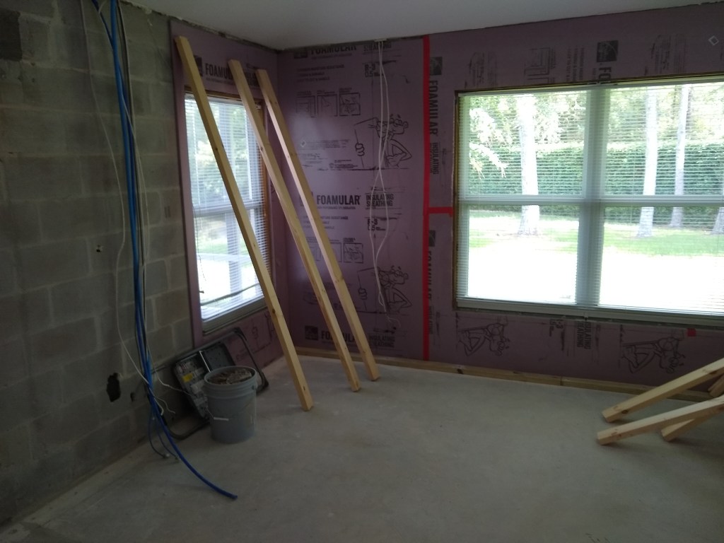
One of the lessons I learned from doing the master bathroom was the importance of having flat walls. The walls in the master shower were flat, but the wall behind the vanity was not, so I had a lot of “mud framing” to do to get it close to flat. This could have been avoided if I had paid more attention to the flatness before the drywall went up. So this time I paid close attention to make sure all the studs were aligned, and planed down those that stuck out and added shims to those that were recessed. It’s a nuisance, but well worth it when it comes time to finishing the walls. I also added blocking at the bottom of the walls where baseboard with be added.

Blocking and Shimming South Wall

The shims are thin strips of cardboard layered on top of each other. Using this material made it easy to fine tune. Also, notice that I added blocking for the other side of the wall too, which is the guest bedroom. That wall will have baseboard, so this will make it easier to attach. Unfortunately, I didn’t think of this on any other walls I did, so I’ll have to do it the usual way by searching for studs when nailing the baseboard.

Blocking and Shimming North Wall

Since there will be very little baseboard along the wall where the vanity will be, I only added blocking for the cabinet to attach to. I did add a piece of blocking for the wall outside the entrance to the bathroom to make attaching the baseboard there a bit easier.

With the blocking and shimming done, I was ready to hang drywall. But first, I had to go get it. And to do that, I used my fancy new rail system I created for the top of my car. Below you see seven 4×8 sheets of blue drywall. The color blue indicates it is water resistant, which is appropriate for a bathroom.

Drywall Successfully Transported using homemade Rail System

I began hanging the drywall on the ceiling, nearest the outside wall. Since I had already installed the shower curb, it got in the way of my lift, so I could not position it directly under the location I desired. So I added a temporary cleat to the wall above the window, about an inch below the ceiling, and moved the lift as close as I could. I then lifted the sheet almost to the ceiling before sliding it over and onto the cleat, which you can see below.

Hanging the first Ceiling Board

Once supported by the cleat, I raised it all the way and started securing it with screws. If you look really closely, you can also see that I applied construction adhesive to the joists. I do this with all my drywall to help ensure it does not come loose in an effort to avoid “screw pops”. Here it is after securing it.

First Ceiling Board in Place

The second board was a bit easier, as I was able to position the lift exactly where I wanted it. The final piece was small enough that I did not need the lift.

Ceiling Hung – View from Entrance
Ceiling Hung – View from Window

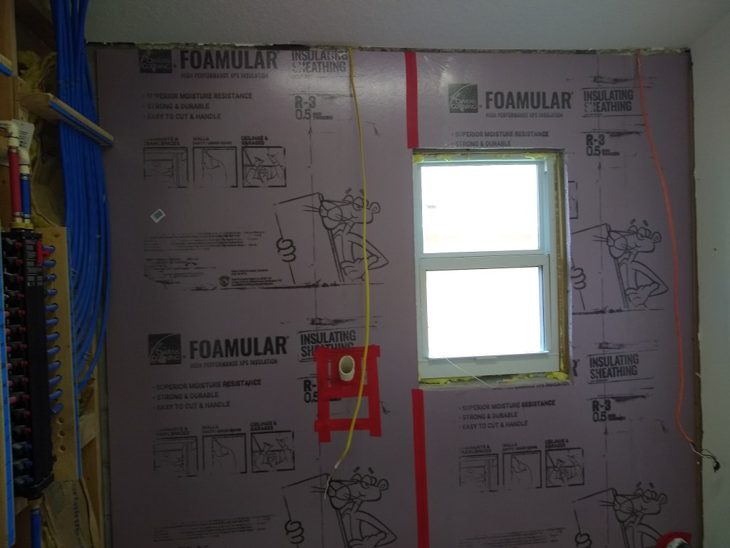
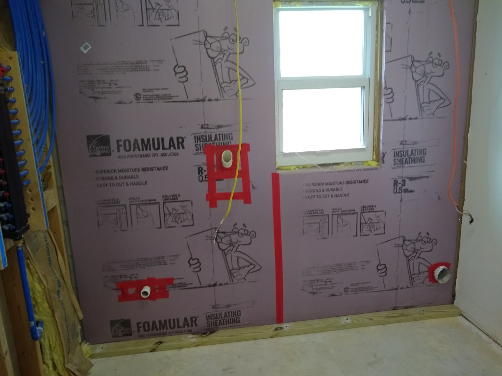
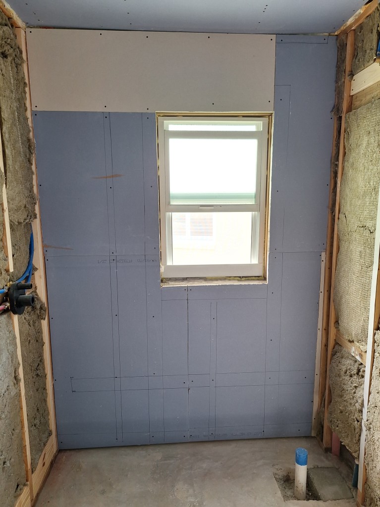
Before hanging the drywall on the walls, I added sound insulation, as usual. It’s amazing the difference it makes, especially in such a small space. After adding the sound insulation, the room just feels solid.

Sound Insulation Added – View from Entrance
Sound Insulation – View from Window

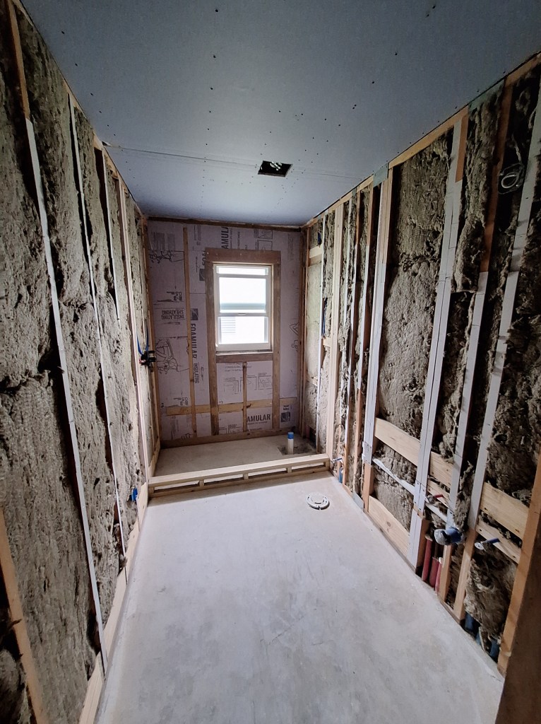
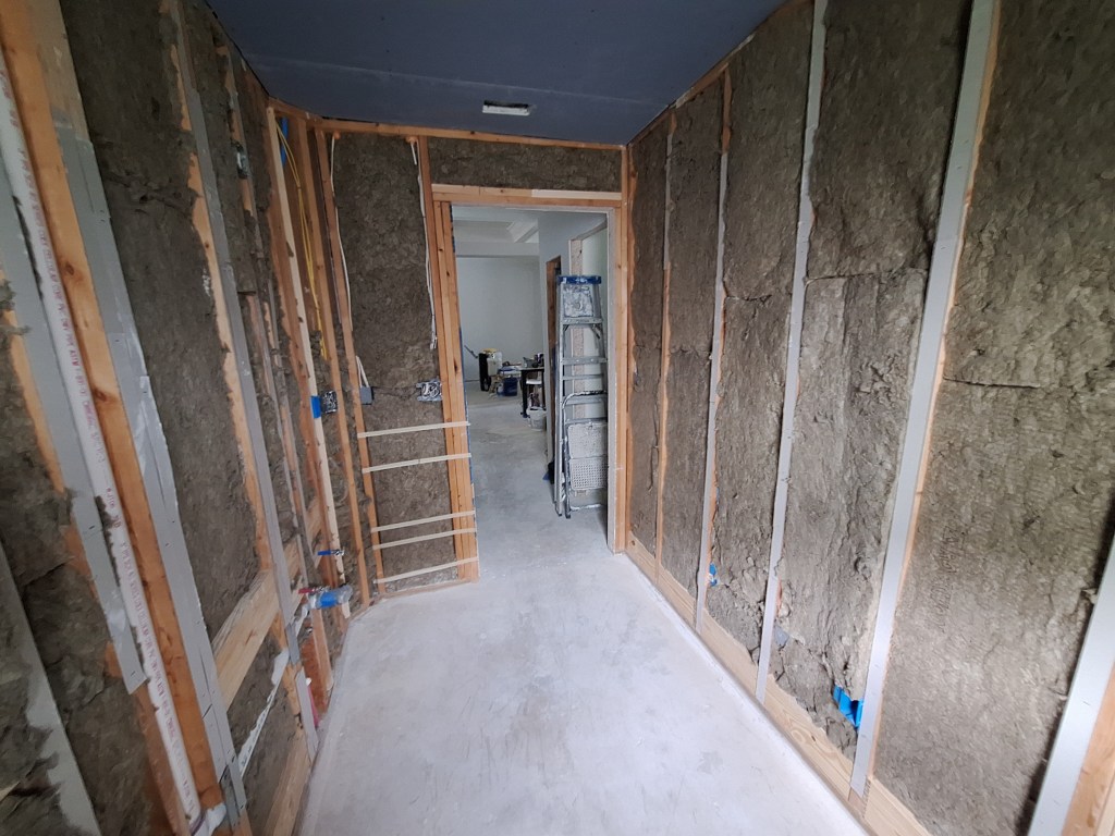
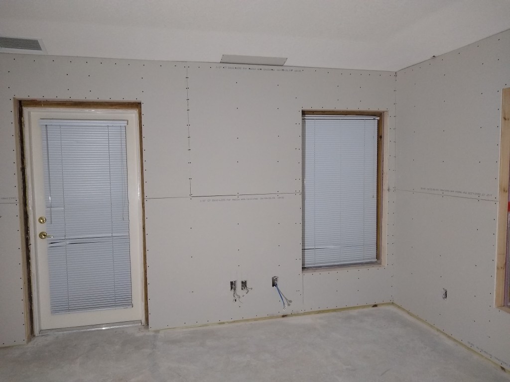
And here it is covered with drywall.

Drywall Hung – View from Window
Drywall Hung – View from Entrance

When cutting out the holes for the water supply lines and the drain, something happened that really annoyed me. I hung the top sheet first; the one that touches the ceiling. That went well. The sheet below it is the one where I had four round holes to cut in order to make room for three water supply lines and one drain. I was carefully measuring their locations, referencing them from the edge of the drywall that touches the curb and the lower edge of the top sheet I’d just hung. My measurements were aimed to locate the center point of the cut (I used a drill and a hole saw to make the cuts). I cut the three supply line holes first, then switched to a slightly larger hole saw for the drain. After making that cut I pushed the sheet against the wall and everything fit perfectly except the hole for the drain. Then I realized that after being so careful with the other ones, I made a silly mistake when measuring for the drain. Instead of measuring down from the top sheet to the center of the drain, I measured to the top of it. So that is why you see a sizable gap above the drain. The other holes will be covered by flanges, but I’ll need to do some repair work on the hole around the drain. Even if I could find a large enough flange to cover it, I will still want to improve the situation.

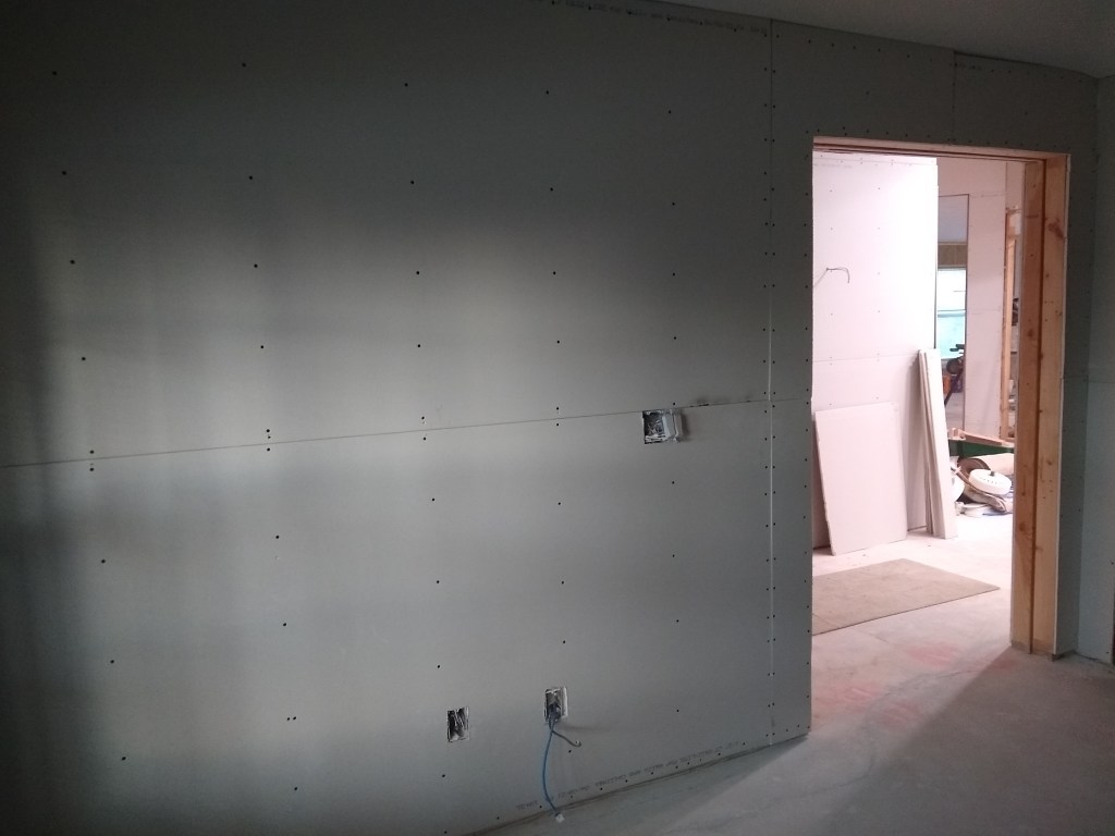
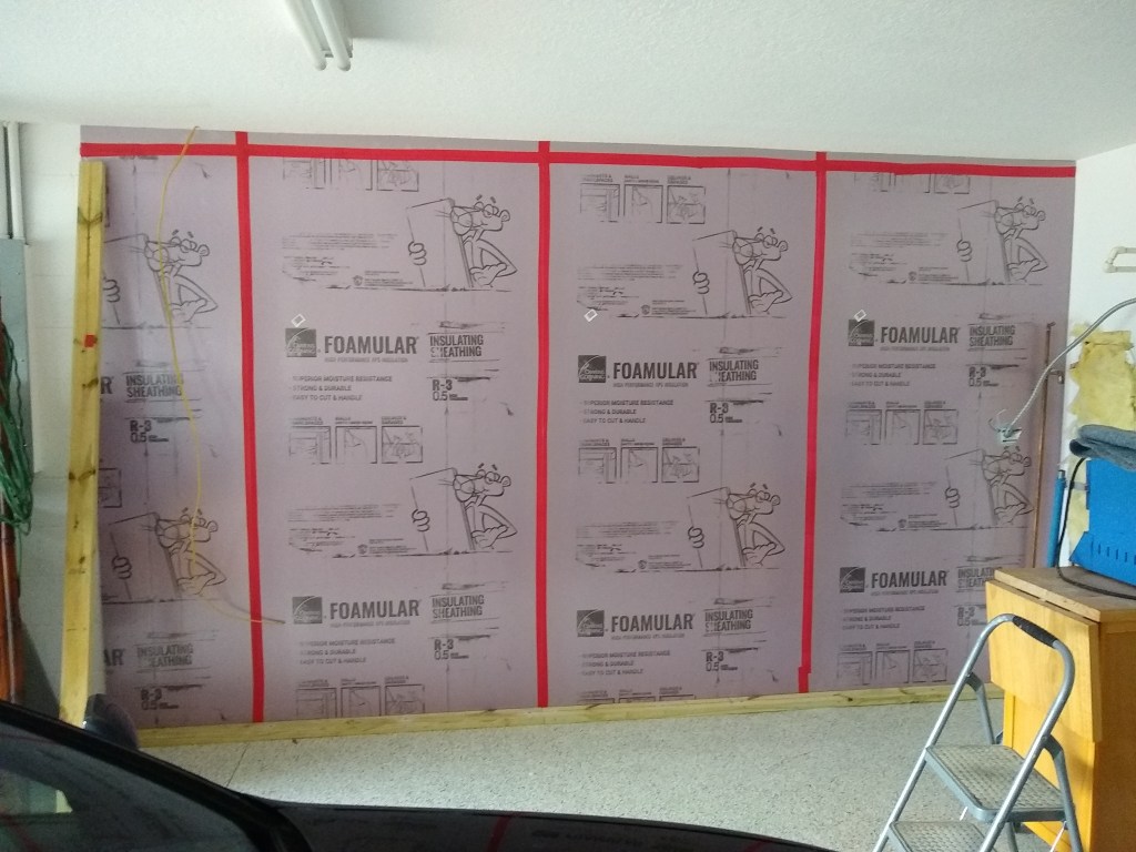
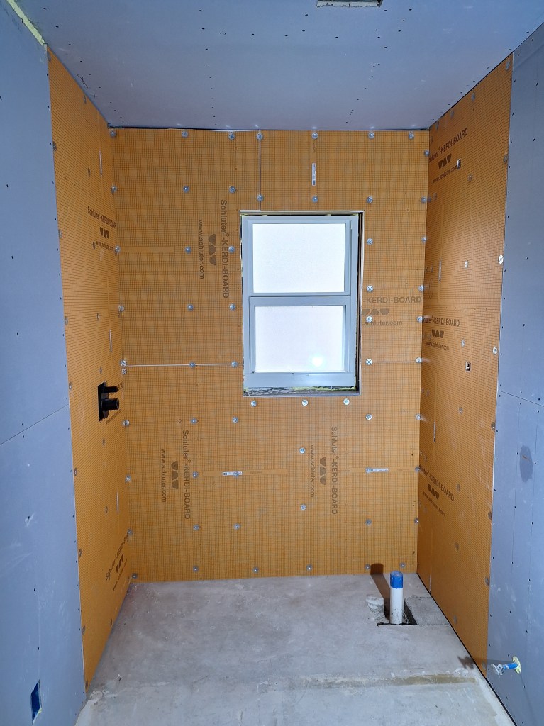
I scheduled a drywall inspection, which is required before I start taping. While waiting for that, I started work on the shower area. I was about to start putting up the Kerdi board on the exterior wall when I realized that the thickness of the Kerdi board (1/2″) plus the thickness of the furring strips (3/4″) attached to the concrete block wall was less than the length of the screws (1-5/8″). I needed at least another 3/8″ to avoid hitting the concrete block. This was not a problem in the master bathroom because all the walls surrounding the shower were interior walls, meaning there was 3-1/2″ of stud to drill into. Rather than add to the thickness of the furring strips, I decided to use the extra drywall I had, which was 1/2″ thick, and attach it to the furring strips. It came out like this:

Drywall added to Build Out exterior Wall.

This worked really well and I loved that I was able to make use of the extra drywall. Since this would all be hidden behind the Kerdi board, there was no need to tape it. All the lines you see drawn on the drywall are there to identify where the underlying furring strips were located. This would be needed when attaching the Kerdi board, which you can see below.

Kerdi Board Hung on top of Drywall

One of the consequences of having to build out the exterior wall, was that I was reducing the space within the shower. It was already a bit tight, and I didn’t like that I was making it tighter, even if only by 1/2″. So I started entertaining moving the curb over one stud. Recall that I added an extra stud on the outside of the curb to serve as a nailer for the drywall. I could shift the curb to align with this stud and gain an extra 1-1/2″. But it was not as simple as that because I also had to take into account the distance between the toilet and the curb. The curb was initially located 15″ from the center of the toilet flange which, from what I read online, was what you want in order to provide enough elbow room. Moving the curb out by 1-1/2″ would reduce that space. However, what is more important is the distance from the center of the flange to the glass wall that will sit on the curb; the thing that will impact your elbow. The glass wall will sit in the middle of the curb, which means I’ll get back to the 15″ I wanted. So I was comfortable pushing the curb out to widen the shower space.

While thinking this through, I did a bit more research on the Schluter curb product. The Kerdi curb is something you attach to the floor using thin-set mortar and is covered with a waterproof membrane, just like Kerdi board. It is strong and can support a glass wall/door. The benefit of switching to this, is that it doesn’t need to be screwed down to the concrete floor, giving me more flexibility when positioning it. So I can keep the area open until I absolutely have to put it in place. One less thing to step over. Below you can see the remainder of the Kerdi board in place and the curb removed.

Kerdi Board Installation Complete

Next, I prefilled the drywall, then taped.

Prefill and Taping Complete

I also added Kerdi band to the seems and to cover the screws in the shower.

Drywall Taped and Kerdi band added in Shower

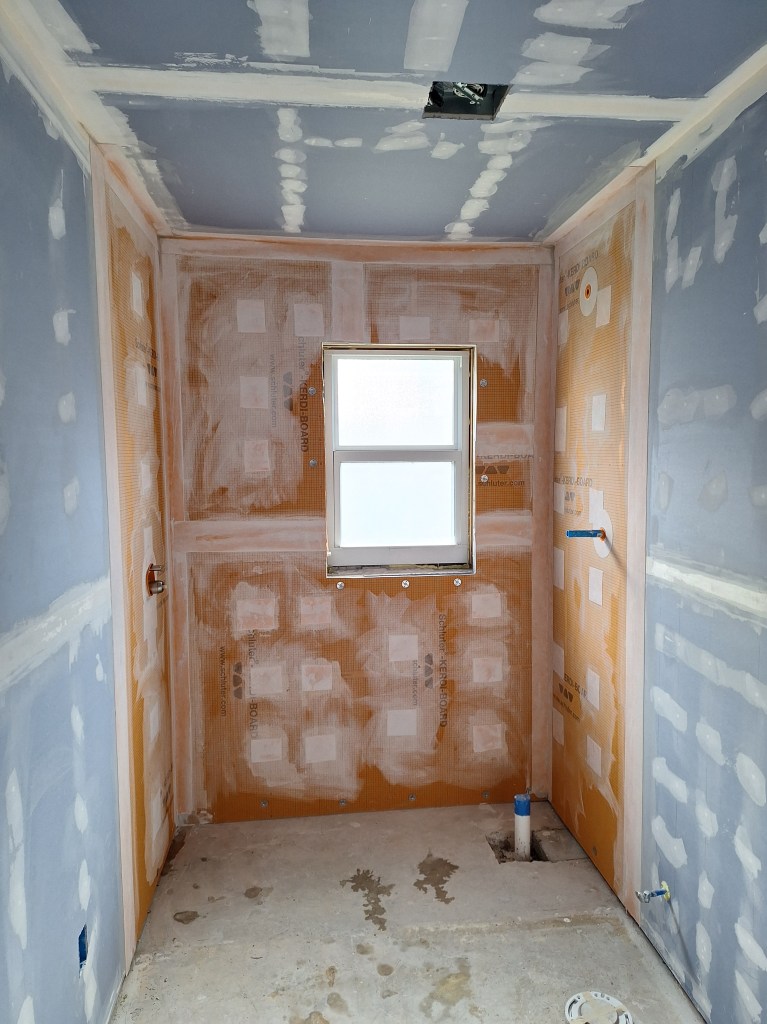
I left the screws around the window and near the floor uncovered because they will be addressed when I add the shower pan and waterproof around the window. Next will come the cover coats to the drywall. I don’t plan to do anything on the floor (i.e., shower pan) until the walls and ceiling are at least primed. Since this is the last day of October, I’ll close the post here and continue in the next post.

Ceiling Prep, Garage Cabinets, and More Drywall Hanging – January/February 2023

After returning from the holidays, I knew I would still be waiting for a while before I would have anything from Jennifer, so I decided to continue work in the garage as best I could. I was still missing a 24″ pantry cabinet that would be the center cabinet along the back wall of the garage, so I did as much as I could in the meantime. This meant adding baseboard, painting the walls, and installing two cabinets of the five cabinets that will go along that wall.

This was all I could do along the back wall since the next cabinet to go in was the missing 24″ pantry cabinet. Not wanting to be idle, I shifted my attention to a task I was not looking forward to; preparing the kitchen and great room ceilings for painting.

Prepping the ceilings meant filling all cracks with wood filler, sanding, then caulking. This would be a long, slow, and laborious task, and one that would require standing on a scaffold working above my head. However, it is a very important task, as it would mean the difference between a great looking ceiling and something less than that. So I got to it.

First Coffer Prepped
First Coffer Prepped, alternate angle.

I started with the kitchen ceiling and then moved on to the coffered ceiling. I didn’t take any pics of the kitchen ceiling because there wasn’t much to show other than sanding marks and such. You can kind of see it in the background of the images above. These images are the only ones I took of the coffer prep because once you’ve seen one, you’ll have seen them all. I had 17 coffers to prep and the images above are of the first one. It took about four weeks to complete both the kitchen ceiling and the coffered ceiling. It was hard work, but I am pleased with the results. Once the primer goes on, I’ll know if any further action is needed, but I suspect not (only very little if any). I don’t plan on priming/painting the ceiling until all the walls are ready to prime/paint, and that is a long way off.

I finished the ceiling prep work the day before the missing garage cabinet arrived, so I was able to return to the cabinet installation in the garage right away. I finished installing the cabinets along the back wall in a single day, resulting in this:

Back Wall Cabinets

Note that above the base cabinet on the right, I will add open shelving, but not anytime soon. Here is a shot of all the garage cabinets before adding the hardware.

All Cabinets Installed

The next day I added the handles. Doesn’t that look nice!

Handles Added
Handles and Butcher Block Countertop

You’ll also notice that the butcher block counter top is in place along the east wall, but not attached. It is still wrapped in plastic and I won’t remove the plastic and apply finish to it until I have moved in (or am at a stand still – heaven forbid), as it is of low priority. I’m still waiting on the corresponding countertops for the outside base cabinets on the back wall, but, again, no hurry.

With the work in the garage done for now, I was ready to return to work on the inside of the house, but unfortunately and frustratingly, still no construction drawings from the designer. We had settled on the design changes to the kitchen and master bathroom, so she is supposed to produce construction drawings that I will submit to the permitting office to update my permit. Not wanting to wait, I scheduled an inspection of the master bedroom (framing and electrical) so I could push on. The inspection went without incident, so I resumed work in the master. The first job was to add insulation.

Once that was done I started hanging drywall. I started on the south wall.

South Wall

The next day I worked on the west wall, which required I first add a patch to the ceiling where I previously opened it up to feed the Ethernet cable.

West Wall

I used the two remaining 12 foot long sheets along the west wall so that I could limit the butt joints to above and below the window, so less work required when taping.

I continued in a clockwise manner to complete the room.

North Wall
Northeast Corner
East Wall

On the ceiling along the east wall I had to do another patch, again due to adding an Ethernet line.

When the inspectors came to look at the master bedroom, I also had them look at the wall in the workshop that I framed. Recall that I originally hung drywall along the west wall of the workshop only to pull it down when I discovered that the entrance to that room was messed up. So I framed that wall as I did in the master and had the inspectors give me the okay on it too.

West Wall of Workshop Framed

So I insulated and hung drywall along that wall next.

My next step will be to bring the inspectors in again to okay the drywall I just put up so I can begin taping and mudding. My preference was to call them in only after all the drywall was up, but with the poor response time from the designer, I am requesting inspections piecemeal so I can push on with the things I can control.

I will be off to Cancun for a few days to meet up with family and friends to celebrate a significant birthday of a family member, so I will resume work at the beginning of March.

Plumbing Closet and Bits and Pieces – September/October 2022

In my last post I ended by stating I would call in an inspector for the framing. I did that and the inspector showed up, but unfortunately I was not ready for a framing inspection. The inspector informed me that, although I had completed (most) of the framing, it is not ready for inspection until the plumbing and electrical are done because they can impact the framing. So that was good to learn.

I also mentioned at the end of the last post that I had a problem to fix that was of my own creation. In the front bedroom that will become the workshop, the door opening was not right. The right side was wider than the left (as you enter). You can’t hang a door properly with that.

Although in the above shots it’s hard to see the problem, I show them so that you can get some idea of the repair that took place. I pulled down the drywall in order to get a better idea of what was going on.

From what I could tell, the furring strips where the problem. I had not accounted for the extra thickness they added on the other side of the door opening. But rather than adjust for that, I decided I would frame the entire wall as I had done with the master bedroom and the like. That would provide the same benefits and solve the alignment problem too. So that’s what I did.

Wall section Framed

With that issue fixed, I started working on the electrical and plumbing that would affect the framing. This involved adding new wiring and and securing the existing wiring to the new framing. I started by adding ample outlets to the east wall of the garage. These will be GFCI protected and required 12 gauge wire.

For the master bedroom I ran some new wire under the large window so that one of the outlets next to the bed will be controlled by a switch as you enter the bedroom. Another outlet in the master bedroom was already controlled by that switch, but it was in a place that was of no use to me, so I rerouted it.

Also in the master bedroom, I fashioned a couple of supports to secure the conduit for the Ethernet and the PEX pipe for the spigot.

PEX and Conduit Secured
A Closeup

I secured the laundry room outlets for the washer and dryer.

Although not required for the framing inspection, I removed the tiles from the floor of the master shower. I had been watching a lot of YouTube videos about how to create a shower pan, so while I was “in the neighborhood” I decided to take care of that task.

I then moved to the laundry room to hook up the drains for the washer and the utility sink (that will be relocated to the garage) and their respective supply lines.

Washing Machine Box with Drain and Supply Lines in place
Drain and Supply Lines in place for Utility Sink (to go on other side of wall).
Big Picture

With the laundry room plumbing hooked up, I could now start building the closet to enclose it. I started by opening the ceiling some more so that I could install nailers to support the framing that was to come.

After that I attached the bottom plates for the closet. The closet will have a 24″x80″ bi-fold door, so the opening you see below will accommodate that.

Ready for Framing the Closet

Although it is just a small closet, the sloped ceiling made it a bit tricky. I was only able to get two sections put up that afternoon. I was hoping to do it all in one day.

If you look closely at the section next to the garage door, you’ll notice that there is no vertical framing member up against the adjoining wall. This is because I did not have the room for it (the red PEX pipes are in the way. Because of that I will add OSB sheathing along that side to provide extra support for the drywall when it goes up. It will be tight, but there will be a small gap between the drywall and the garage door casing when it’s all done.

The next day I was able to finish the framing.

Plumbing Closet Framed

Here you can see the OSB sheathing I mentioned above. The opening in the ceiling outside the closet will be drywalled. I made sure there was sufficient nailing surface for that. I don’t think I will do anything inside the closet to pretty it up; only add insulation. There are places where I could add drywall, but I don’t think I want to close anything in. I want to be able to get full access to all the plumbing, so I think it will remain raw. I can always change my mind about that later. I also may find that I want a light in the closet some day, so keeping it unfinished makes that easy.

The remaining work related to the plumbing closet involved wiring up the 3-way switch, moving the switch in the garage for the garage light, and patching the opening I left when installing the PEX. Here’s a reminder of that big hole.

And here is the repair.

From the image on the right (above), you can see where I moved the switch for the garage light. In the original position it was a bit of a reach. Because the switch box for the 3-way switch for the laundry room light was occupying that space (nailed to that stud), the original builders used the next closest stud to attach the switch box for the garage light. Since I had to move the 3-way switch to the side of the plumbing closet, that space became available, allowing me to move the garage light switch to the more convenient location.

Above left is the newly hooked up 3-way light switch positioned on the side of the plumbing closet as you enter the laundry room from the garage. In the image on the right I’m showing the wiring behind it. Notice that I had to introduce a junction box to extend the existing wires. Even though the switch was only moved a foot or so from its previous location (just around the corner), there wasn’t enough slack to make up that small distance. Since I had to add extra wire, I decided to move the existing wires to a location within the closet that was less likely to interfere with the red plumbing lines, which is why you see them coming down from above.

I still have more plumbing and electrical work to do before I can re-request a framing inspection, but some of that is dependent on the design I’m waiting for. I’ll be meeting with Jennifer (the designer) this coming week, so I hope to have more information to guide my next set of tasks and the content of the next post.

Framing Continued – September 2022

In the last post I just finished framing the exterior wall of the master bathroom. My next job was to clear out the tools and such from the master bedroom and get to work framing its three exterior walls I imagined the job of clearing out the master would be a big one, but it didn’t take me too long, so I was able to get right to putting up the foam board on the south wall.

South Wall with Foam Board

As you can see, I used some of the many 2x4s to help keep the foam board pressed against the wall as the adhesive takes hold. I also put down the pressure treated 2x4s that attach to the concrete slab with tap-con screws. While doing that I realized that I had to put up the foam board for the adjacent walls in order to get the dimension for the pressure treated boards correct, since they would be butting up against the foam board on those walls too.

The next day I returned to do the actual framing of the south wall.

South Wall Framed

The next day I started on the west wall and managed to get the foam board up and half the wall framed. So I was getting faster.

Foam Board up on West Wall
West Wall Half Framed

Having made good progress the previous day, finishing up the west wall didn’t take long the next day.

West Wall Framed

Although I made quick work of the remainder of the west wall, I could not start on the east wall of the master because I had to install a spigot on the outside of that wall, and for that I was waiting for the delivery of a special drill bit to create a 1-1/2″ hole through the concrete block. Not wanting to end my day early, I turned my attention to the garage wall that will receive cabinets. As usual, it begins by putting up the foam board.

Foam Board up on Garage Wall

You’ll also notice if you look closely, I fed the electrical wire down from the ceiling. This will power the outlets along that wall. The next day, I framed it.

Garage Wall Framed

The day after finishing the garage wall, Jennifer (the interior designer) came to the house. We had a good chat. The next step was for her to send me a proposal of the services they would provide, which should arrive in the next week or so. In the meantime, I would continue with the framing.

While working on the garage wall, the 1-1/2 inch coring bit I ordered arrived. That was nicely timed, as it allowed me to return my attention to the east wall of the master bedroom. I was a bit apprehensive about drilling out the hole for the spigot. I’d never drilled such a bit hole through a concrete block wall. I did a lot of exploring online and it seemed straight forward enough, but there is something unsettling about drilling a big hole in your exterior wall. But it all went very well. I fashioned a little jig out of a piece of 2×4 lumber to prevent the drill bit from wandering as I tried to get the hole started. Below you can see the jig and the long coring bit attached to the drill.

Hole Drilled – Outside View

I kept the jig in place using my foot as I pushed the spinning coring bit into the wall. Once the hold was started, I was able to remove the jig and carry on. While drilling I used a hose to keep the hole wet. The drill bit is a hollow steel tube with diamonds on the end. It was originally painted red, but as you can see, that didn’t last long once drilling started. I would push the drill in for a bit then pull it out and spray some more water in. It went quite well and it didn’t take long before I was through to the other side (about 8″).

Hole Drilled – Inside View

I was happy with the result. It left a nice clean hole. I fed the new spigot through from the outside and it extended just the right amount.

Spigot Installed – Inside View

And here is what it looks like from the outside.

Spigot Installed – Outside View with Cover Open
Spigot Installed – Outside View with Cover Closed

You’ll notice that the old spigot that is attached to the copper piping is still in place. That will just twist off and I will replace it with a cap, which I’ll eventually paint to match the exterior color, so it won’t be too noticeable.

You’ll also notice that the new spigot is kind of different from what you’re used to. it has a separate male attachment that connects to your hose and plugs into the opening revealed when you raise the cover.

How the Aquor “wall hydrant” connects.
Connected

When looking for a spigot to buy, I came across this and was impressed. It prevents anyone from making use of your water unless they have the appropriate attachment. I will add another one to the west wall, but will not replace the one on the east wall because it is attached to the main supply line, before the supply line feeds into the PEX manifold. So I’d have to take extra steps to take it out of the loop. For now, I don’t plan to do that, but I may change my mind once I’m moved it and fancy another project.

With the spigot installed, I could now return to framing the east wall of the master. And here is the result.

East Wall Framed

As far as I am aware, that is the bulk of the framing complete. I still have to create the closet in the laundry room for the plumbing, but that will wait until after the drain to the laundry tub (to be located in the garage) is hooked up.

Next, I turned my attention to repairing the framing of the kitchen extension. This was a job I was not looking forward to. The extension wall, although plumb, was not properly done (I didn’t do it). Two of the three vertical studs did not line up with the studs of the existing wall. If left alone, the drywall would have a slight but noticeable bend. So I had a lot of shimming and trimming to do. On one side of the each of the two studs I had to fill in the concave part of the bend, while on the other side I’d have to chip away wood to ease the convex part.

What made this so tricky was that the shimming was not uniform. It tapered along the lengths of each stud. To make this more manageable, I did each stud in sections. The studs are about 10 feet tall, so I created three separate shims to make up that length. Using my table top 4″ jointer, I planed down each shim a bit at a time, then took it to the wall to see how it fit. I did this over and over again until it lined up with the studs to the right of it. Once satisfied, I used wood glue and a lot of clamps to hold it in place.

Shimming a Stud

Here you can see two of the shims clamped in place. The shims are from left over furring strips I had, so they are wider than the 1-1/2 inch ends of the studs, but that was okay. The extra width didn’t do any harm. Below is an image taken after completing the first stud (it’s a bit blurry, but you get the idea).

On the other side of the stud I used a jigsaw to make horizontal cuts to the appropriate depth every quarter inch or so all along the length of the stud. To determine the depth of each cut I used a level to determine how far out the stud projected relative to those of the existing wall, creating a series of marks over the length of the stud. I then “connected the dots”, so to speak, producing a line at which I could aim. Note that this is just rough framing that will be covered with drywall, so it didn’t have to be precise. It just had to be close, so this approach worked fine. I then used a hammer and chisel to chop out the wood between the cuts. I did not get a picture of the result of this because there was not much to see. I suppose I should have taken a picture or two of the process, but it was a lot of work so story telling was not on my mind. So this is how I went about correcting the misaligned framing. Below are images of the end result with clamps removed.

Shimming Complete
Closeup of the Overhead Section

The overhead section did not require a shim over its entire length. It gradually lines up, so the shims you see above taper down to almost nothing. This means it is a bit wider at one end than the other. I don’t think this will be noticeable once the drywall is up and finished. If it is, then I will address it with trim.

At this point I believe I can call for a framing inspection, which I’ll do next week. While waiting on that I have another error to fix. Something I messed up. I’ll report on that in the next post.

A Lot of Waiting – May-September 2022

In the last post I mentioned that I had finally gotten my permit, so I could resume work. The first thing I did was hire out the work to re-cut the slab so that the electrical and refill could be brought up to code. On the morning of May 18th a couple of fellows arrived to cut into the slab in the master bath and kitchen. In preparation for this, I cleared the spaces, took down the walls for the alcove surrounding the toilet in the master bathroom, and used my chalk line to outline where I wanted the cuts made.

I was really glad I outsourced this job because these guys made quick work of it and were done within three hours. Well worth the expense. Here is the result.

The next day I replaced one of the 14/2 wires with 12/2 and enclosed them in a conduit. I later (months later) discovered that even that was not sufficient. But we’ll get to that in another post.

With the newly issued permit, I decided I would look for someone to do the two bathrooms. To this end I met with Georgette at David Waller Interiors to see if they could help. That seemed encouraging and we set up an appointment for May 26th to have Georgette come to the house along with some of the subcontractors they use. The electrical guy had all sorts of negative things to say, telling me that a lot of the wiring had to be changed because once the walls have been opened up, you have to replace the wire (with exactly the same stuff, only newer). He recommended I get an inspector in right away to assess the situation. After he left, one of the other guys, Richard, who was privy to the exchange with the electrician, told me that it was not so dire and that he knew a guy who could manage the entire project and handle the inspection process. Having done so much work already, I was concerned about the inspections and was very receptive to the idea of having someone help me navigate that space. So Richard put me in touch with Marty, who was a general contractor (GC) he had worked with.

Marty showed up on June 6th. I really liked him and we had a good discussion. I sent him my SketchUp model so they could provide me with an estimate. Unfortunately, on June 20th (two weeks later!) Marty told me he did not want to take the job. He was too busy. That was annoying given that he took two weeks before he bailed out; wasting my time. So I called Richard again and he put me in touch with another GC, Joe.

Joe came by on June 23rd and looked over the place. He mentioned while looking around that it was a bigger job than he expected, so I was not optimistic that he would take it on. So he left and was going to get back to me. On June 28th, having not heard from Joe, I contacted him and he told me that he could not take the job. Too busy. It’s funny how I have to chase these people down just to find out they don’t want the job. This has become a common theme in this industry. I find that it is rare that someone will call you when they say they will. I frequently have to chase them. So I called Richard yet again and he put me in touch with Mike.

I met Mike on June 30th at the house. He seemed willing to take the job and we arrange to meet again on July 7th, at which time he would bring someone else along to take a look. We met as scheduled and Mike and Scott showed up. Scott would be the one managing the project, so I walked him through the house, explaining what I was after. It appeared that they were still up for the job, so I gave them the code to the lock box so they could access the place while I was away on vacation for the remainder of July, returning early August. They planned to bring other trades by to get their input and to determine costs.

I had a conversation with Scott and the plumber while I was on vacation. The plumber needed a few more details. So I was happy to know that Scott was bringing people by. When I returned in early August I contacted Scott to find out what the situation was. He still did not have a number for me, but did have a drywaller scheduled to come by the house. So I met the drywaller at the house. Nice guy, and we had a good exchange. A couple of days later Scott told me that the drywall guy wanted to return to the house to take more measurements and that Scott would drop by too. So I met with them on August 11th and we had a chat.

Scott proposed that we do it in stages. The first stage would be to get the place ready to the point where flooring would be next. I liked that idea because it would be progressive and consequently, I could take over should I choose after each stage. Scott figured he’d have a price for me on the Monday (August 15th). So I was feeling pretty good about that.

On Thursday, August 18th, having not heard anything from Scott, I texted him asking what was going on. I got no reply that day, but did the next day. Scott informed me that he was still waiting to get with Mike to discuss it. Mike was out of town on some personal business.

The next week I was notified by my apartment complex administrator that my lease renewal was upcoming and asking me about my intentions. To answer that and tell them how long I intended to keep the apartment, I needed to know if I was going to hire Scott and company, and that required I have a cost estimate and some idea of how long it would take. So I texted Scott again on the Monday (August 29th). He responded that he was busy on a job but that he would contact me later in the day, which he did not. So the next day I asked again. I got no response that day (like pulling teeth). He did respond the next day, August 31st, giving me a price estimate of $70k. To that I immediately responded that I wanted a breakdown of the costs. I wanted to know where that number came from. It seemed very high for just the first stage. At the time of writing, September 4th, I have yet to hear from Scott.

Given that I seemed to be in a perpetual state of waiting, I decided I had to do something and made an appointment to have an inspector come over and help me understand what I needed to do. I was concerned about doing this on my own, fearing that they would tell me I had to pull all sorts of things down, but I was fed up waiting for people, so I bit the bullet and decided I would open myself up to whatever they had to say. When making the appointment, I explained my situation, which was that I wasn’t looking for a specific type of inspection (i.e., framing, electrical, etc.), that I was looking for guidance more than anything. So they sent two guys over on Friday, September 2nd.

The two inspectors, Chris and Dennis, were very good. They explained a lot to me and made me realize that I didn’t really need a GC to manage this part of the project. There was nothing drastic that needed to be done. Most of the things they pointed out where things I was happy to hear about and can easily incorporate. So I am now thinking I will proceed without the help of Scott and Mike. I’ll pull in the subcontractors myself, as needed. If I do hear back from Scott I will consider what he proposes, but for now I am proceeding as though I am on my own.

As a result of this, I contacted an interior designer. I want to put together a comprehensive plan of what I am doing. So far I have only had a general idea, figuring I would cross the various bridges when I came to them. But if I am going to bring in subcontractors, I’m going to have to have a better idea of what I want them to do. For example, if I bring in a plumber to do the piping to the bathtub, I need to know what bathtub I am getting. Similarly for the vanities in both bathrooms. I’ll also have to know what tiles I want and such. So I’m looking for some help with this and set up an appointment with Jennifer for September 14th.

In the meantime I have started working on the house again, finally! Now that the inspectors have alleviated my concerns, I am ready to resume framing the exterior walls. This includes the laundry room, master bedroom and master bath, and the east garage wall. So I picked up a load of lumber and foam board and got to work on Sunday, September 4th. Here’s what I accomplished:

Framing Started

It’s amazing how good it feels to be finally moving forward again. I wonder if I’ll ever hear from Scott.

The next day, Monday, I finished framing the laundry room and started on the wall in the master bath.

Framing Started in Master Bathroom

On Tuesday (today) I finished the Framing in the Master Bathroom.

Framing Complete

Next I will tackle the master bedroom. That will require that I empty the room, and there is a lot of stuff in it, as you can see. So that will be a bit or work.

I will end here, since this has been long enough. In the next post I will show more of the framing work and hopefully will have something to share about my meeting with the interior designer.