Page 2 of 4

Kitchen – April 2023

This post was written concurrently with the one for the master bathroom, so you should start with that one (Master Bathroom – April 2023) to keep the time line straight.

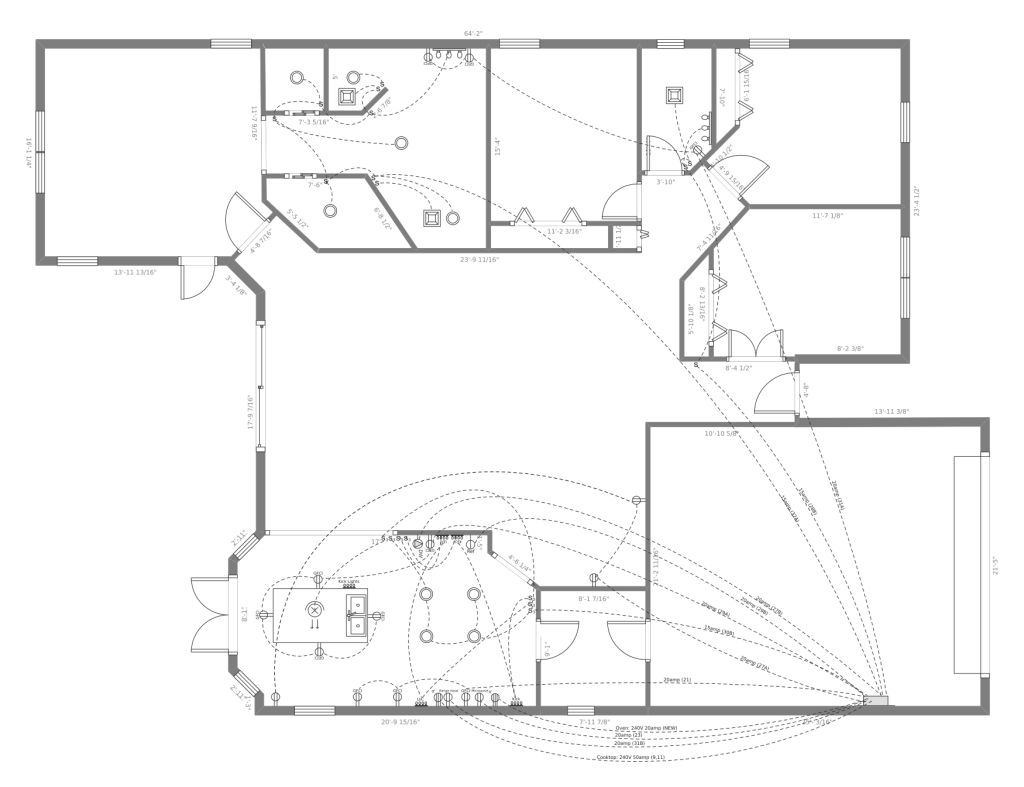
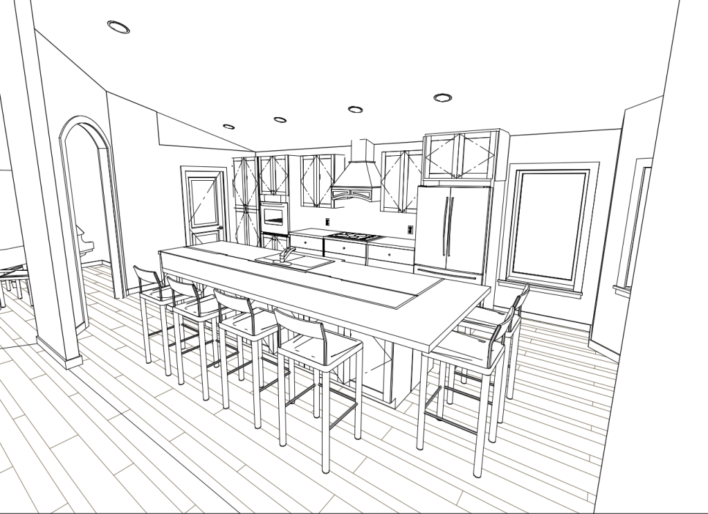
Since I had to wait for the concrete in the master bathroom to cure (I wanted to give it a week to be certain it was safe to drill into it), I turned my attention to the kitchen. While I was doing the concrete work in the master bathroom, I received word that the revisions to my permit, that I submitted a couple of weeks prior, were approved. So now it is time to reveal the changes to the kitchen. I start by showing images of the original plan.

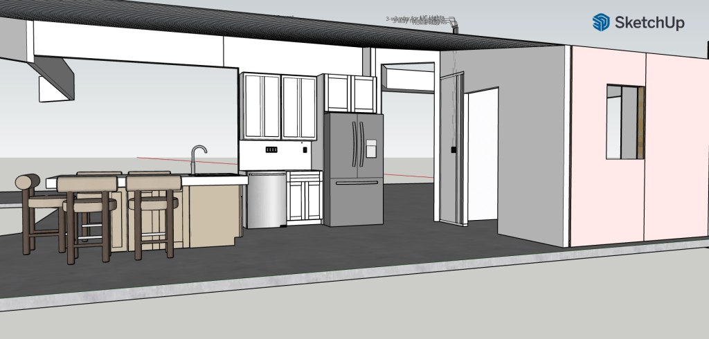
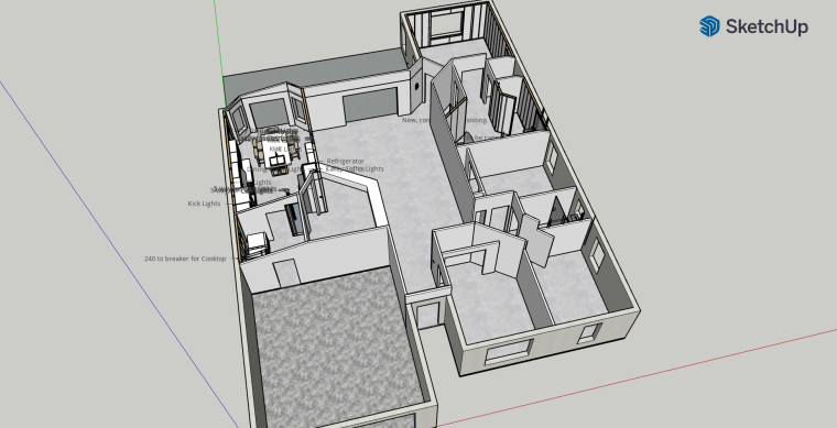
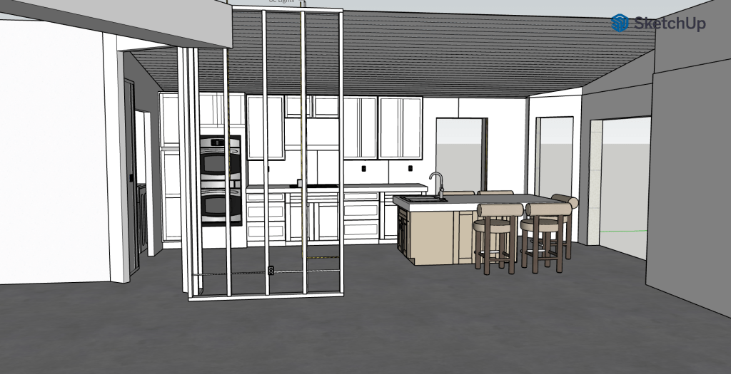
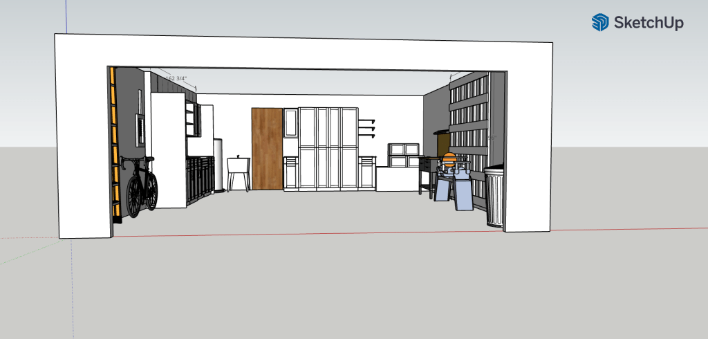
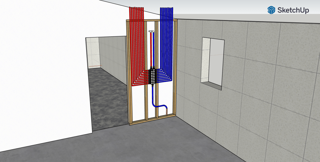
And here is what the new plan looks like.

New Kitchen Layout

This rendering is not exact. It just gives you a sense of what is coming. The entry to the dining room will not have an arch, and who knows what vent hood will be selected. What is worth noting is that I will be removing a significant part of the wall that divides the kitchen from the great room. The designer, Jennifer, convinced me that my original plan provided very little prep space. The part I really liked in my original plan was that I would be looking out over the beautiful view I have as I stood at the sink. But she was right, and this makes more sense. The refrigerator will move to the opposite wall from where it was and the dishwasher will be housed in the island. To prepare for this, I had a lot of electrical and plumbing lines to relocate. I’ll also have to do some more cutting into the slab to route the water and electrical lines, and there will also be some modifications made to the drains (so more concrete to pour in my future – yay!). But that will be covered in another post.

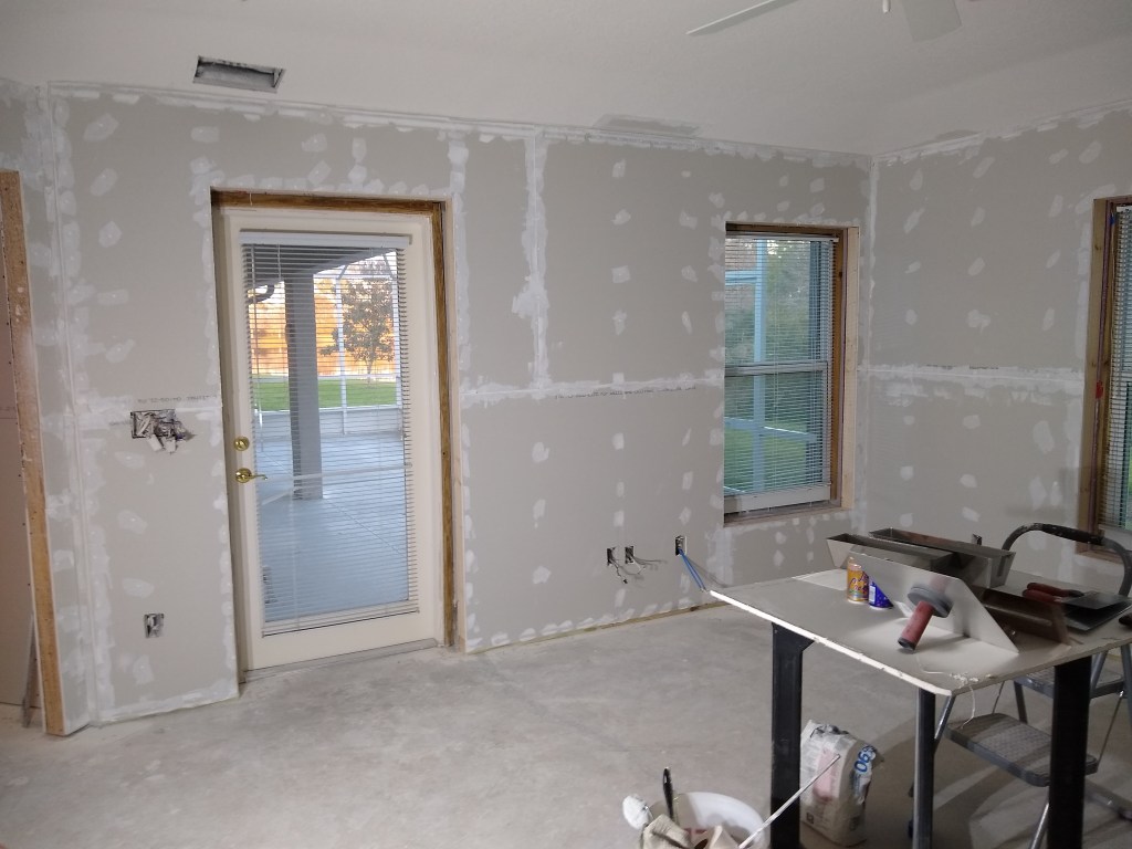
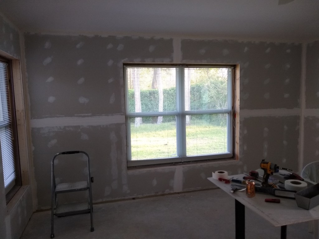
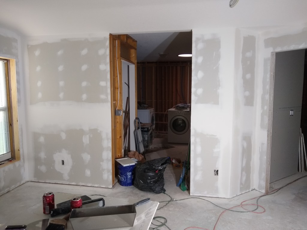
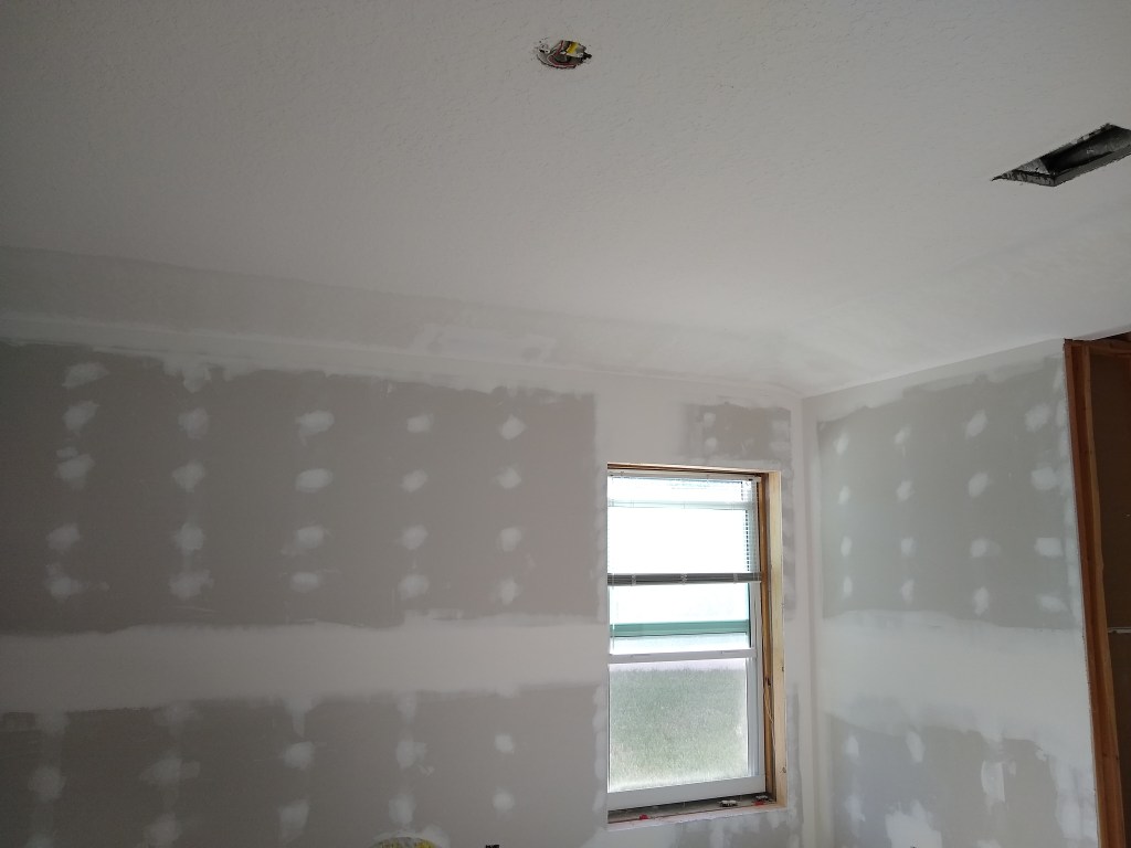
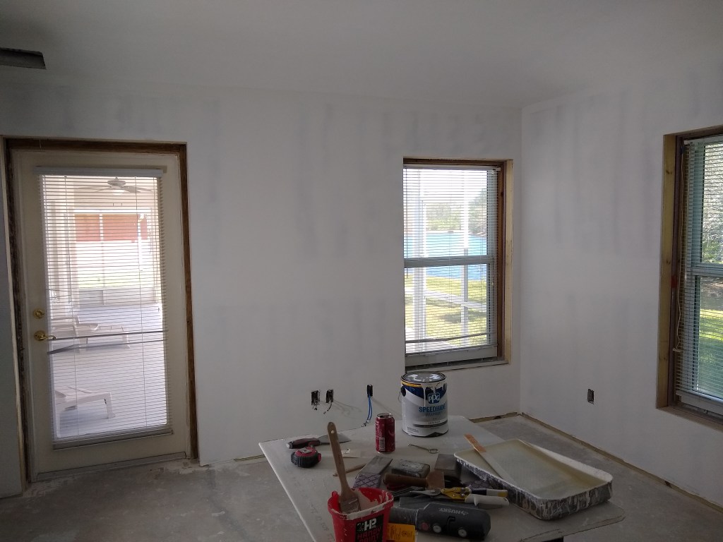
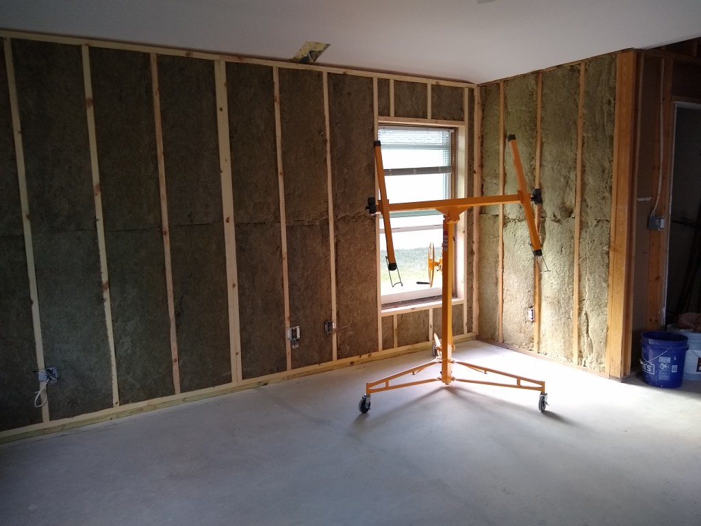
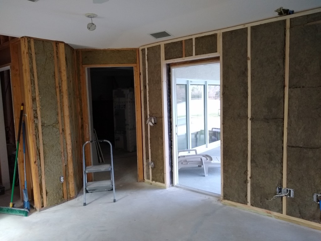
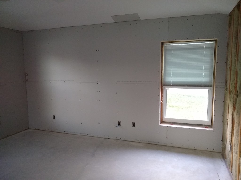
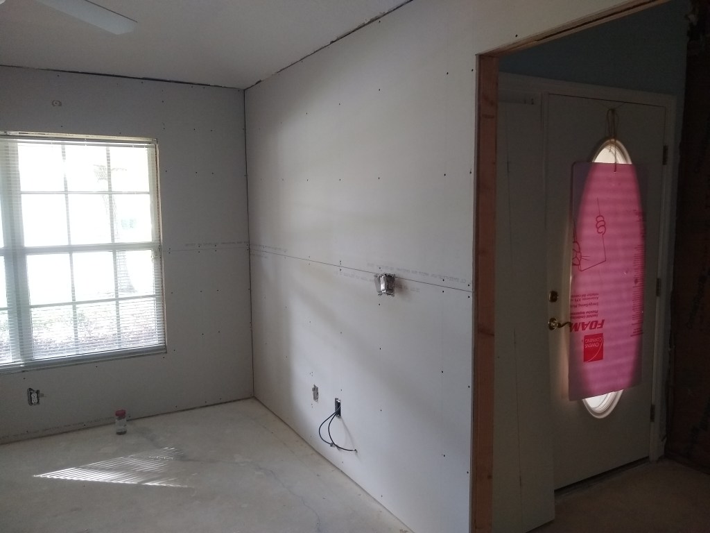
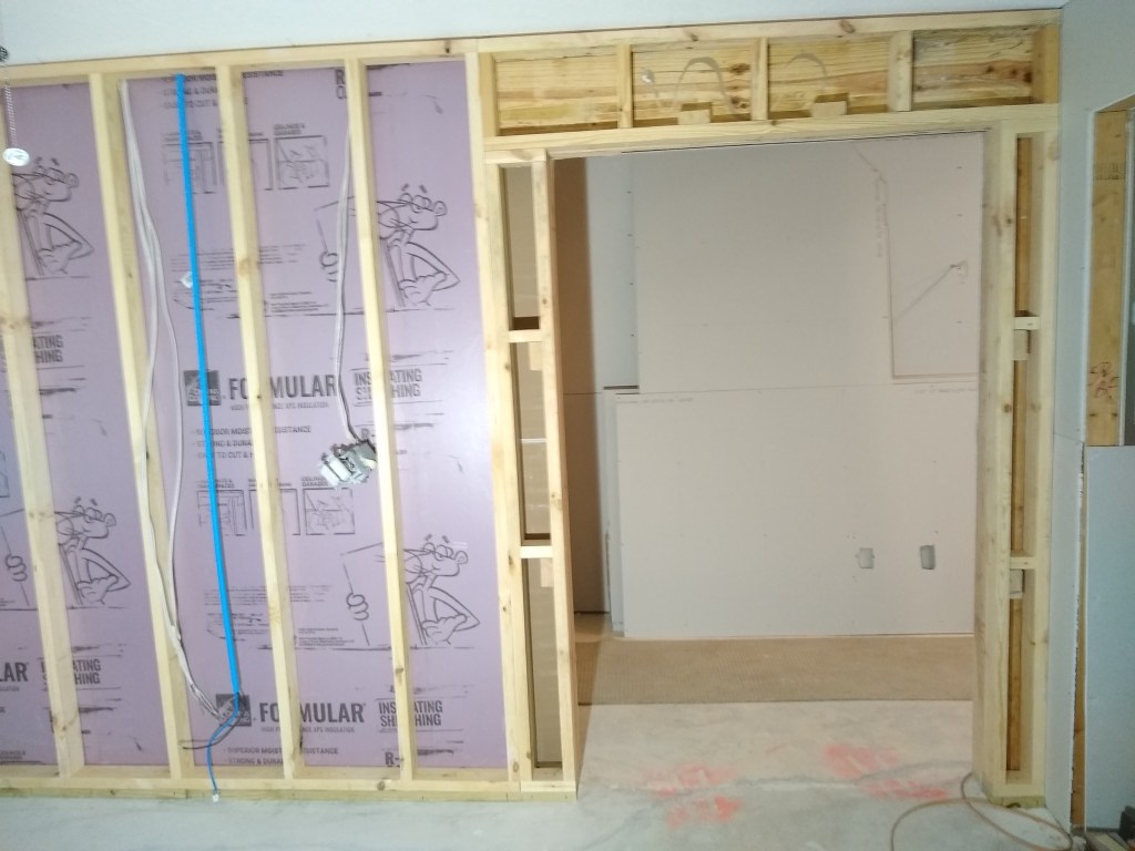
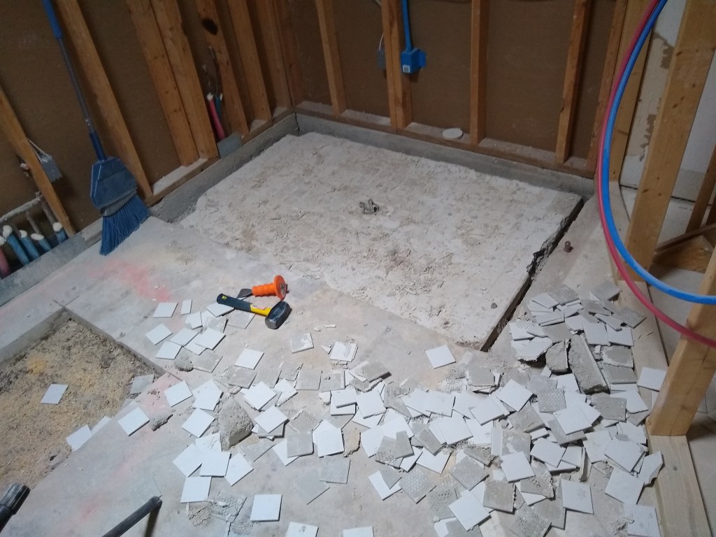
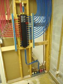
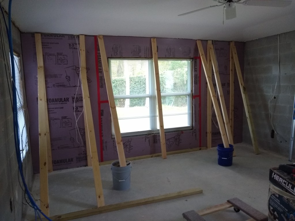
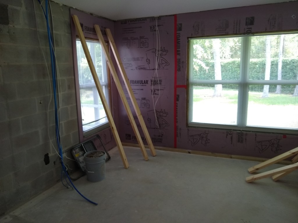
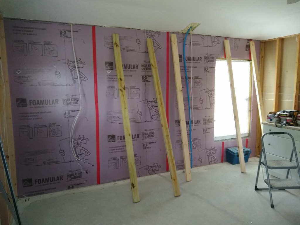
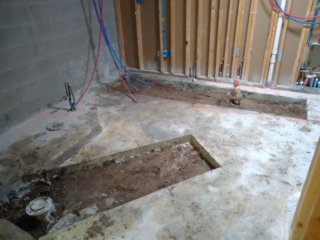
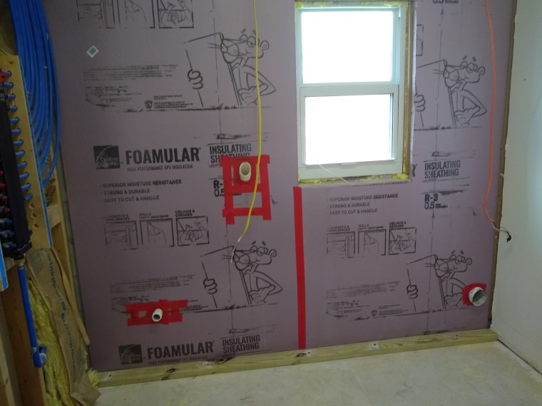
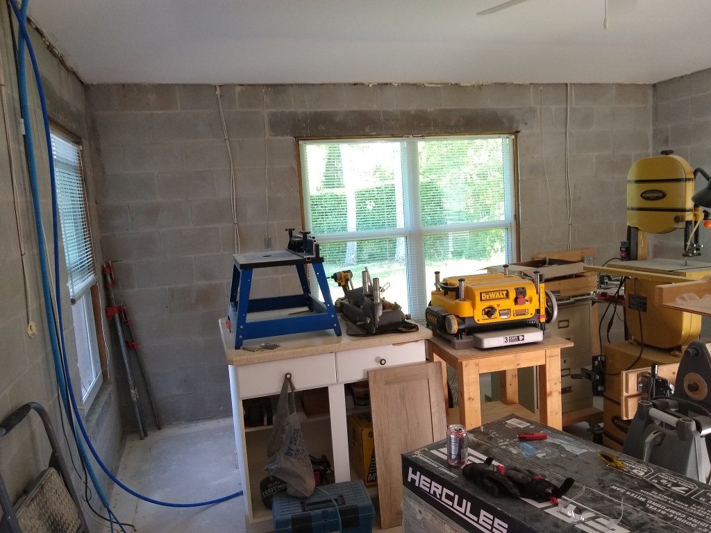
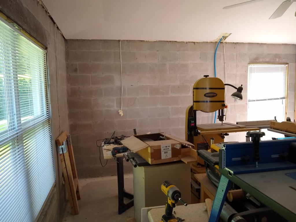
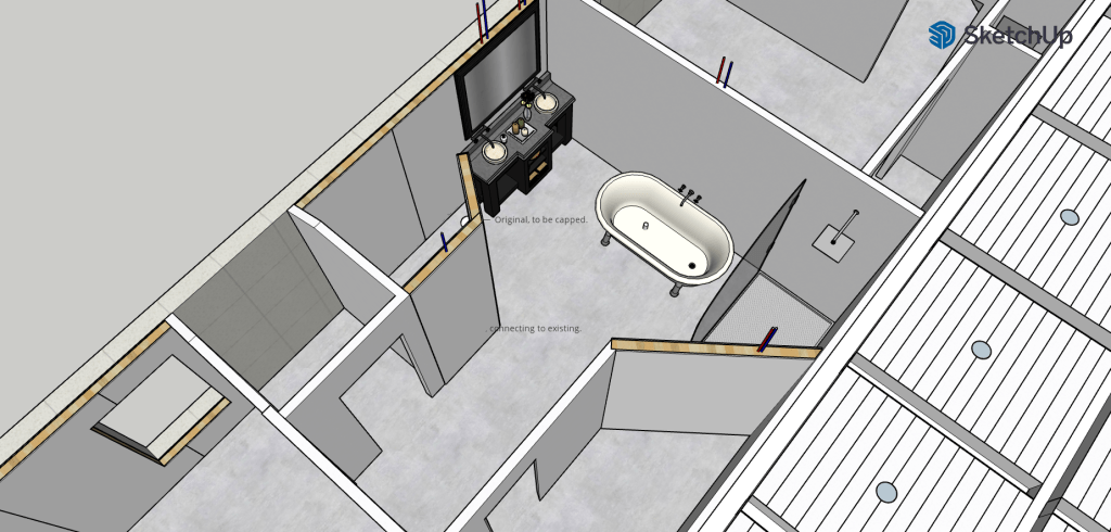
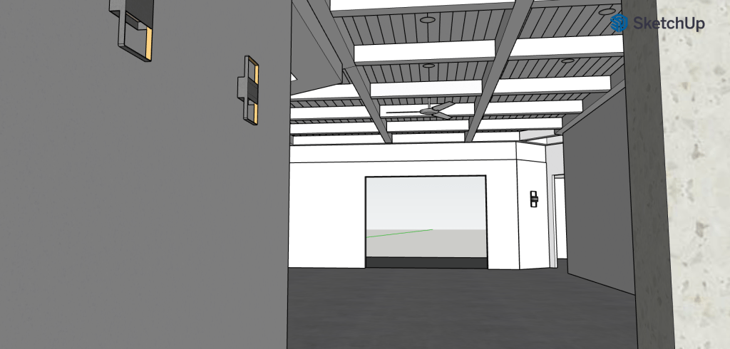
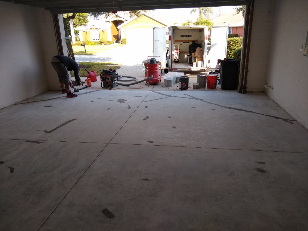
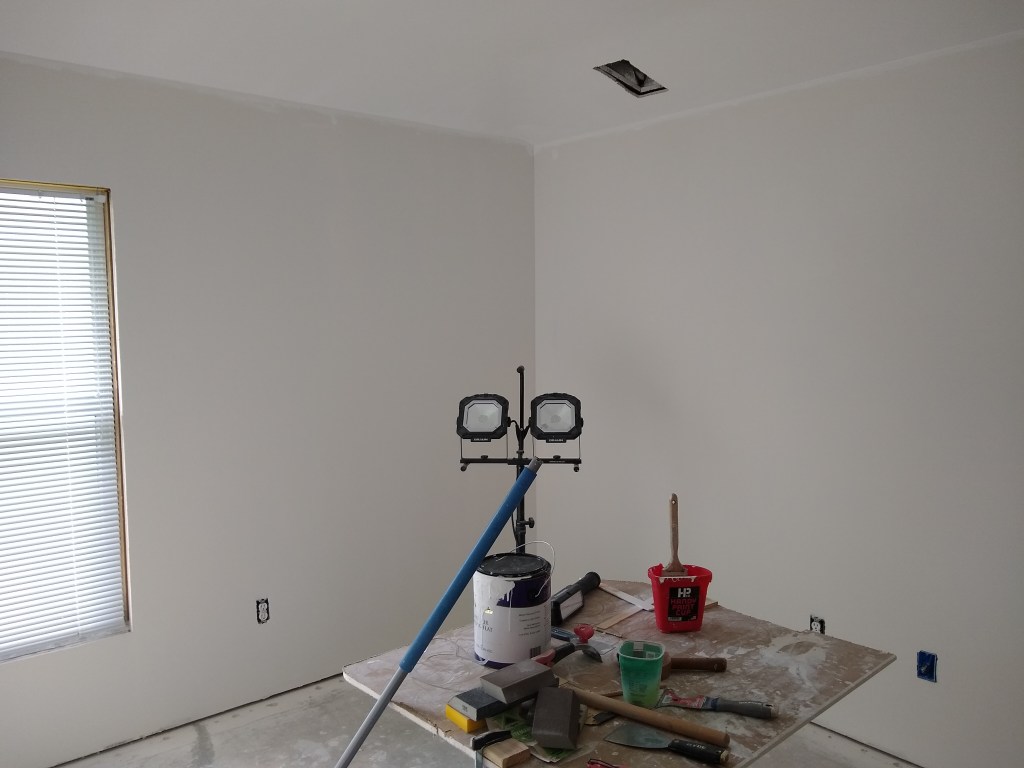
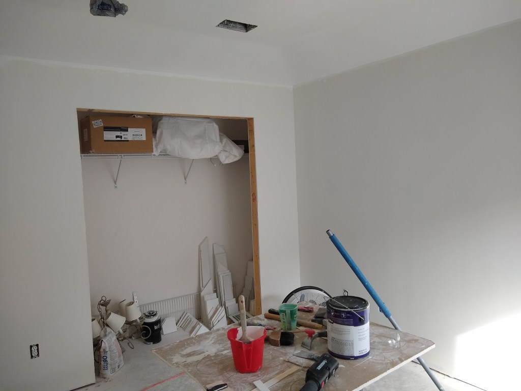
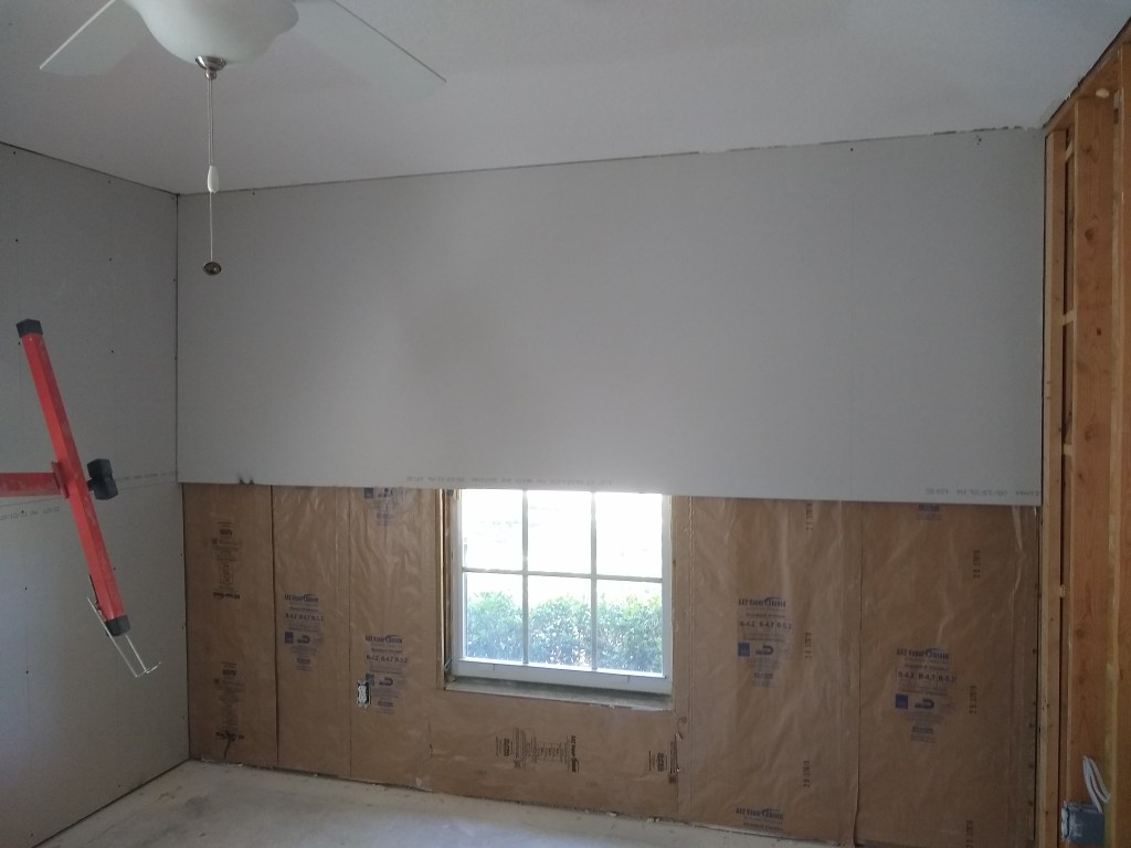
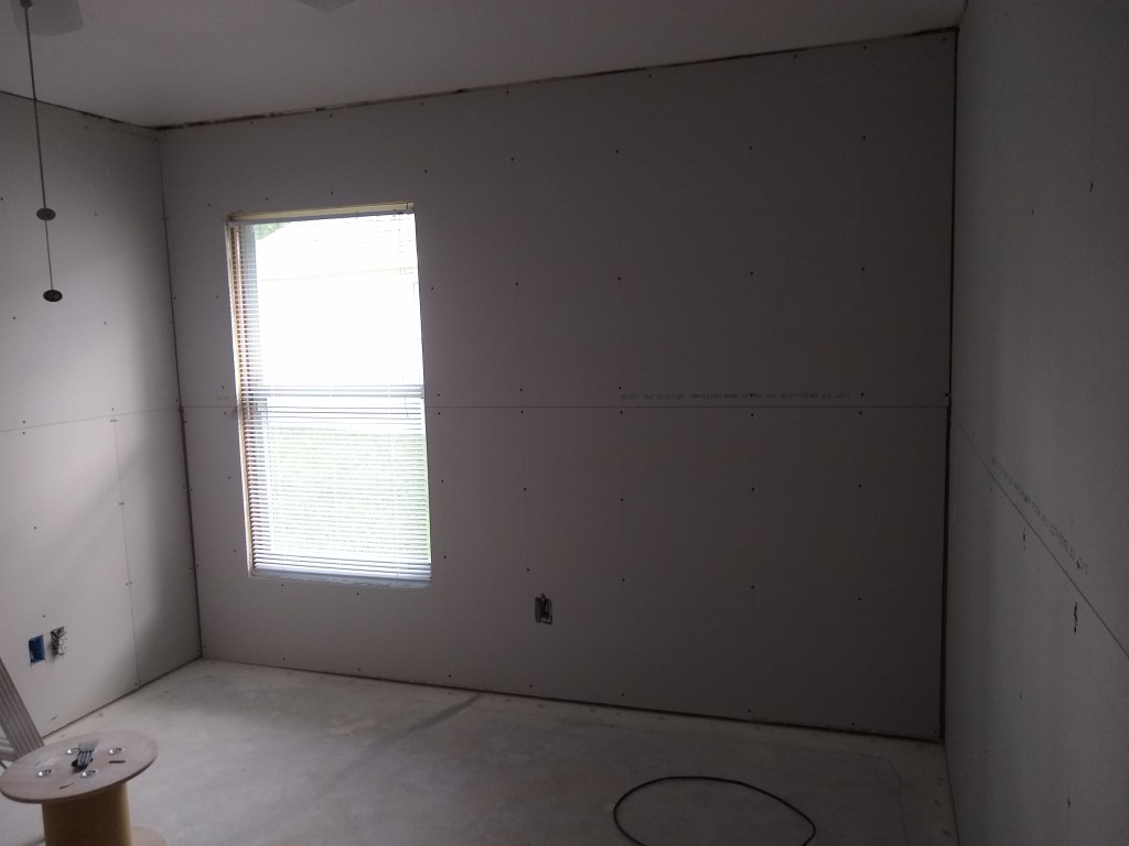
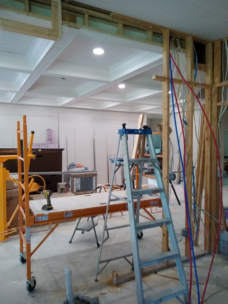
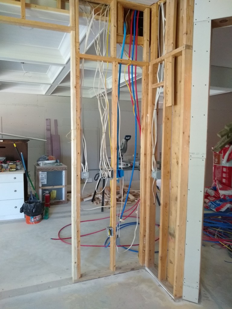
I began by removing most of the existing wall that divides the kitchen from the great room. Here is the before image.

Before demo

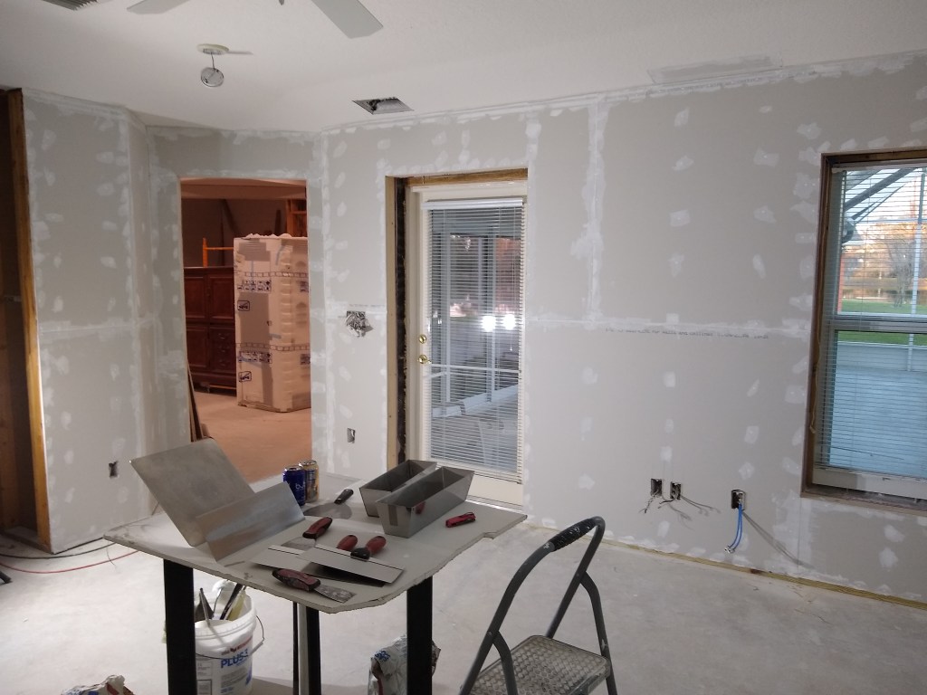
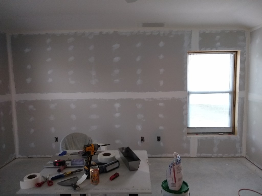
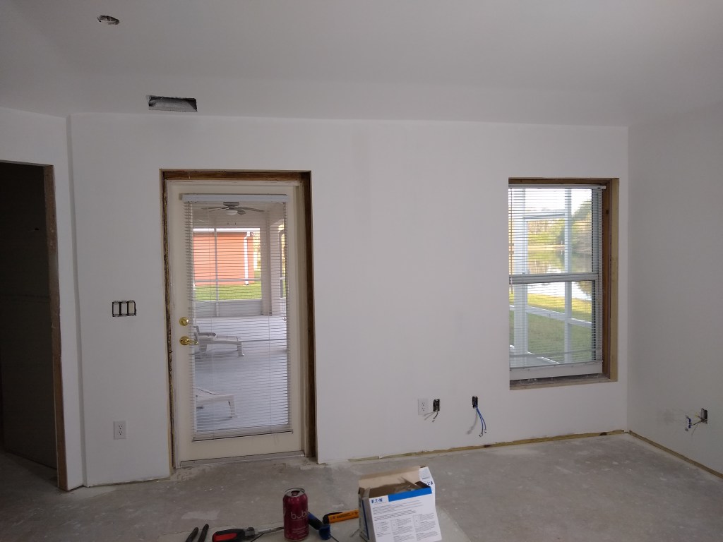
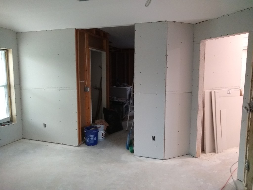
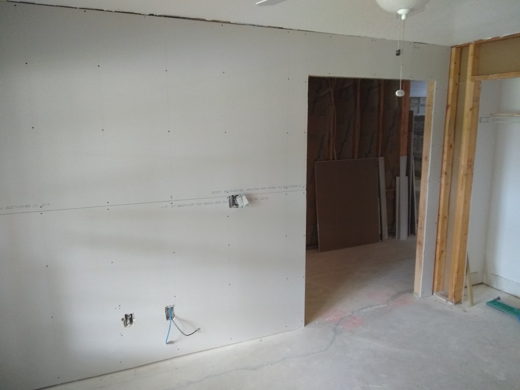
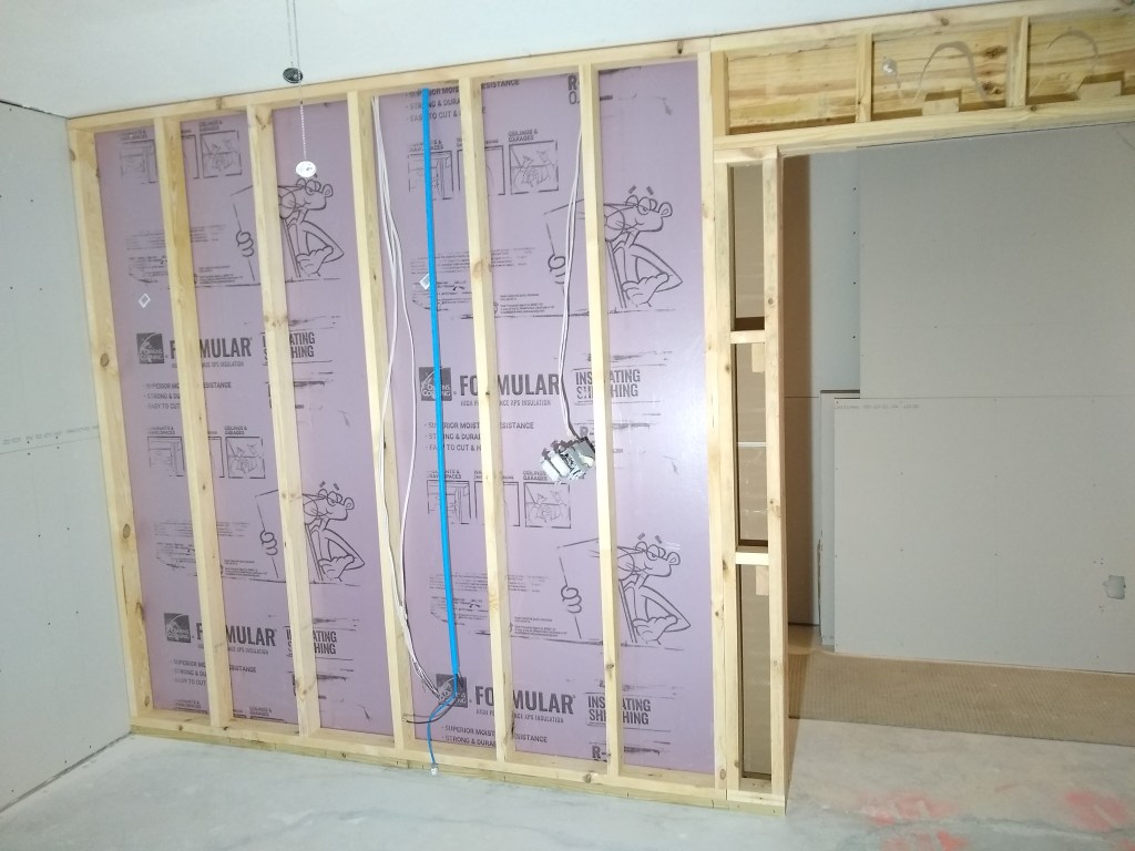
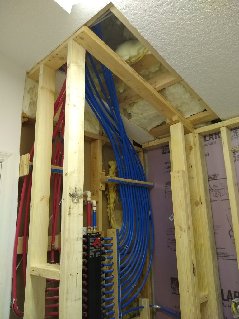
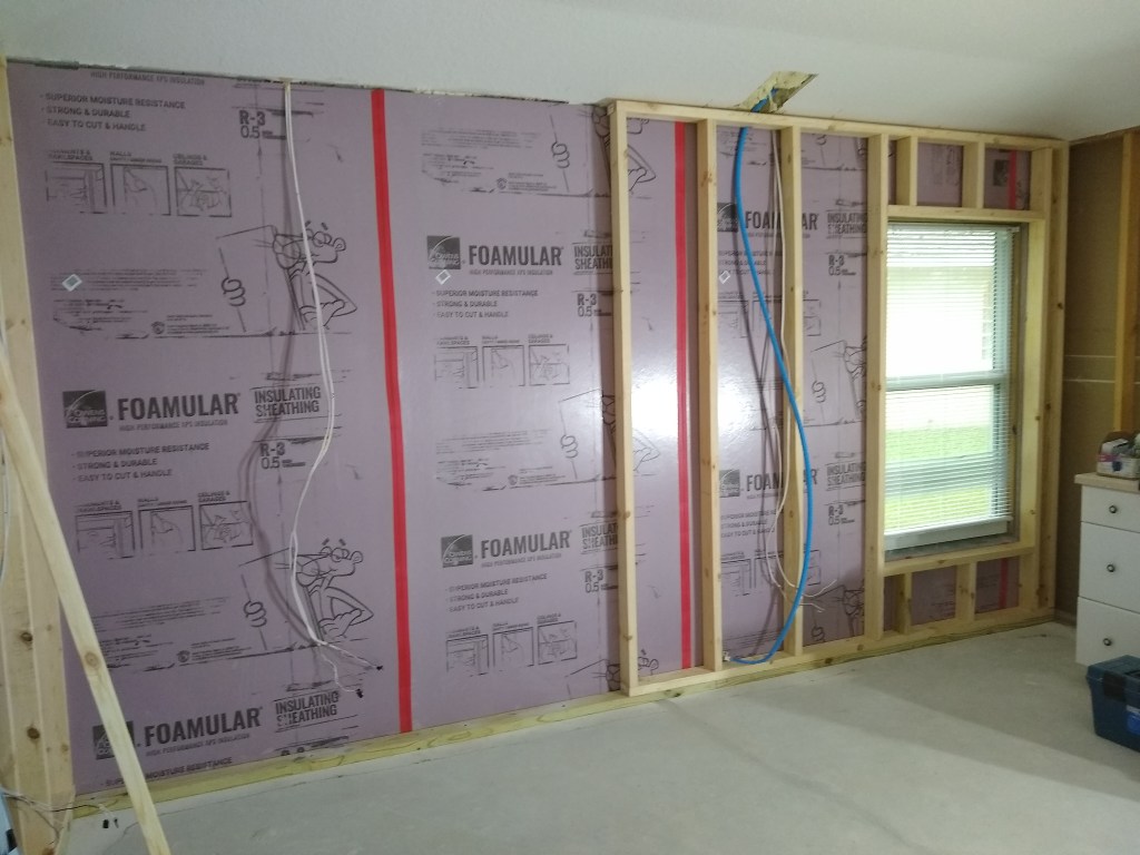
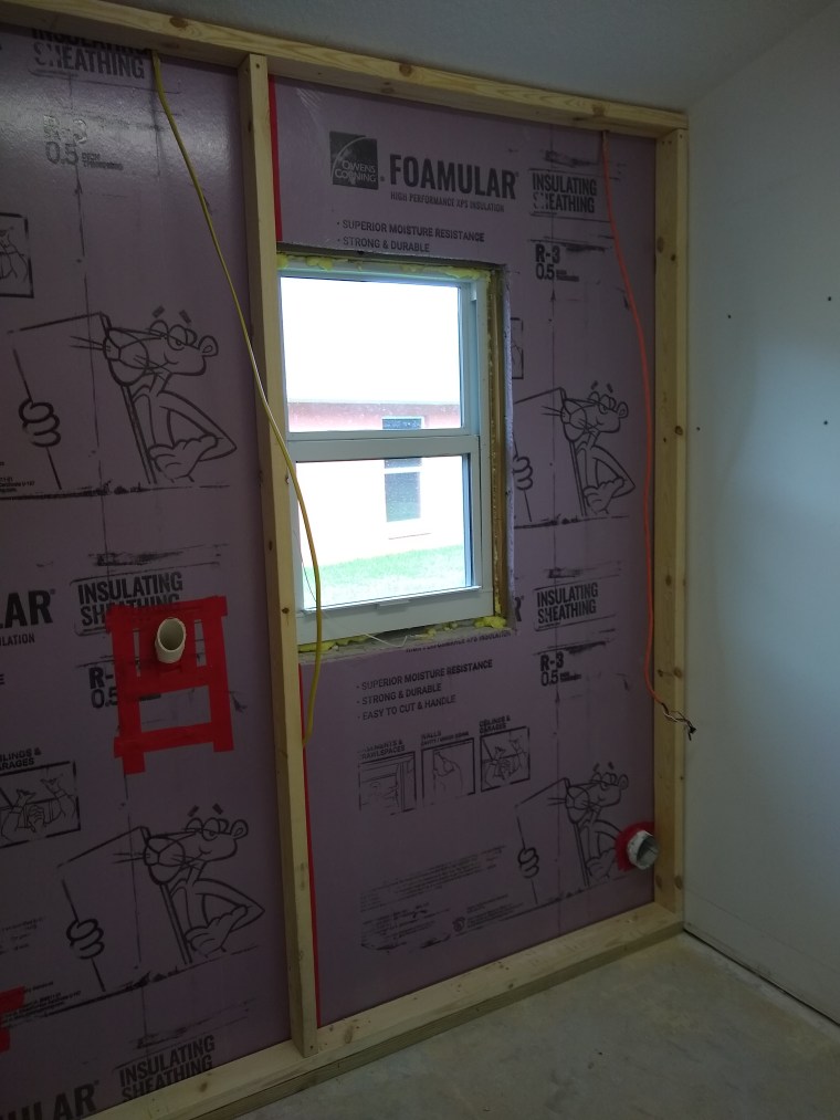
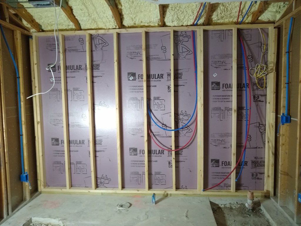
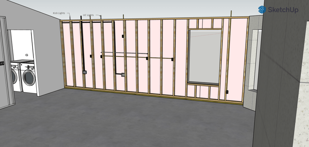
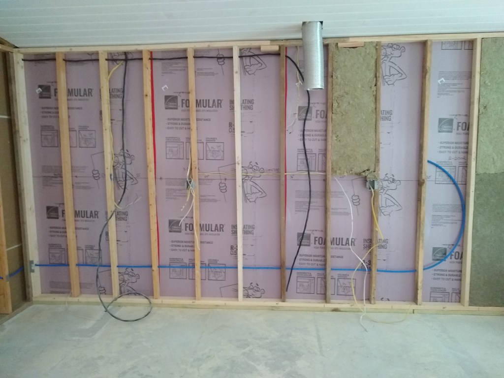
Notice the electrical and water lines that had to be relocated. In the image below I have moved the lines and removed most of the wall.

Removal In Progress

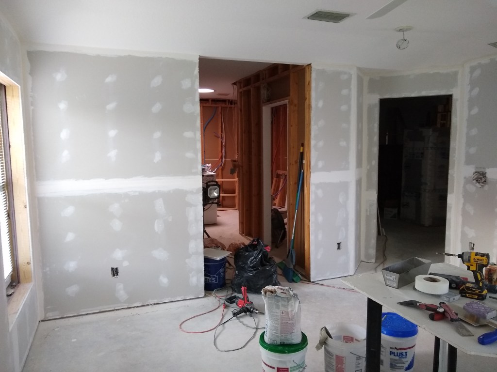
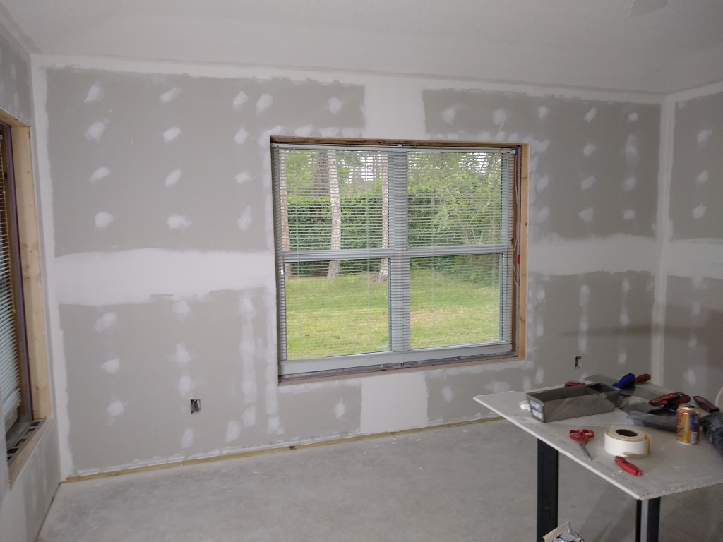
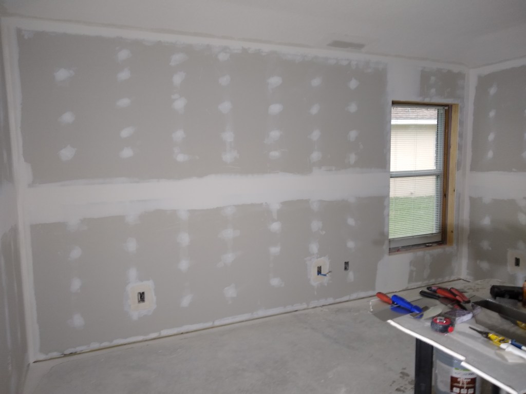
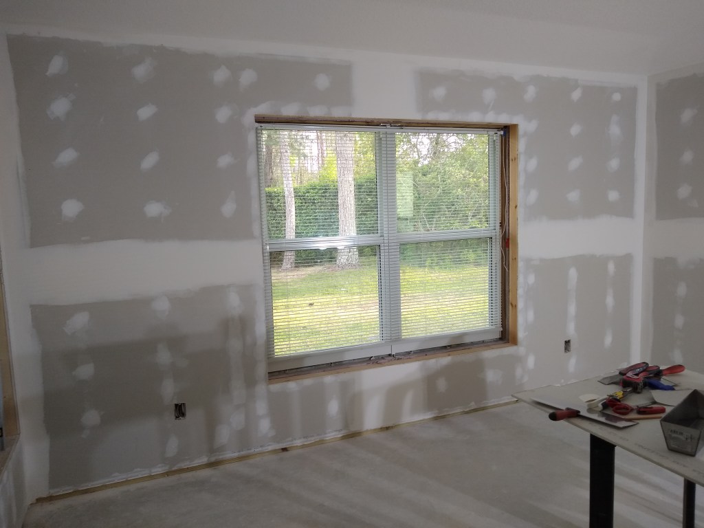
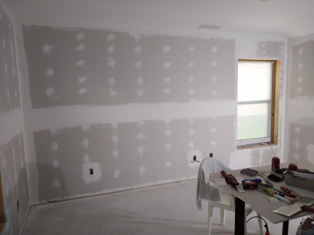
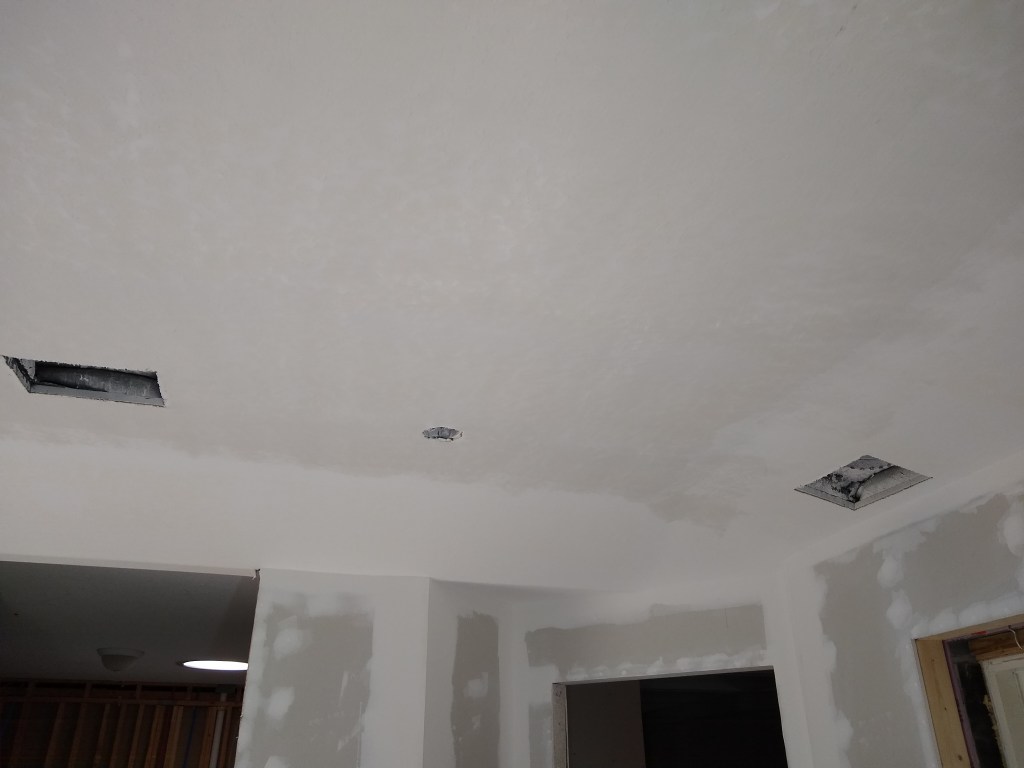
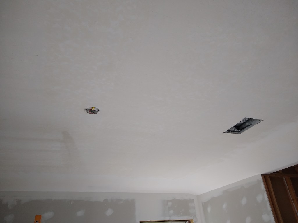
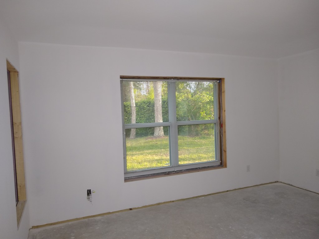
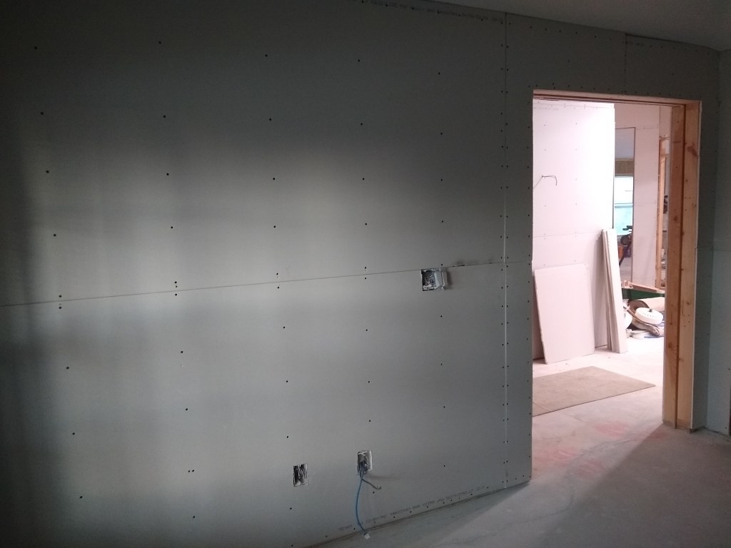
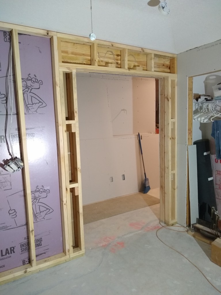
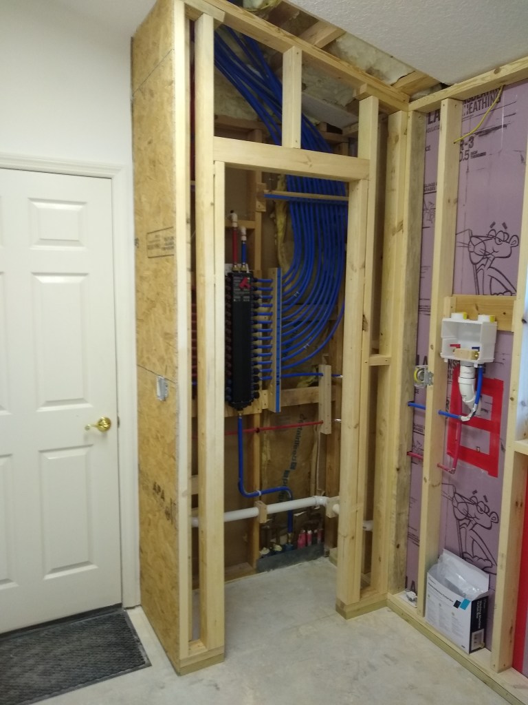
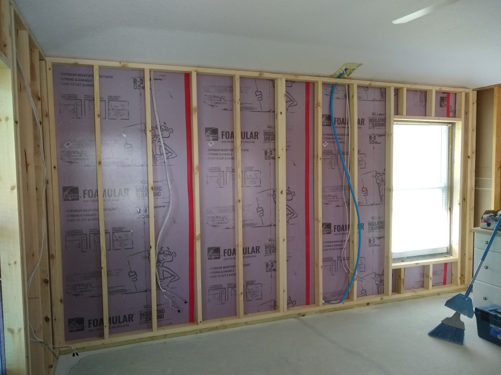
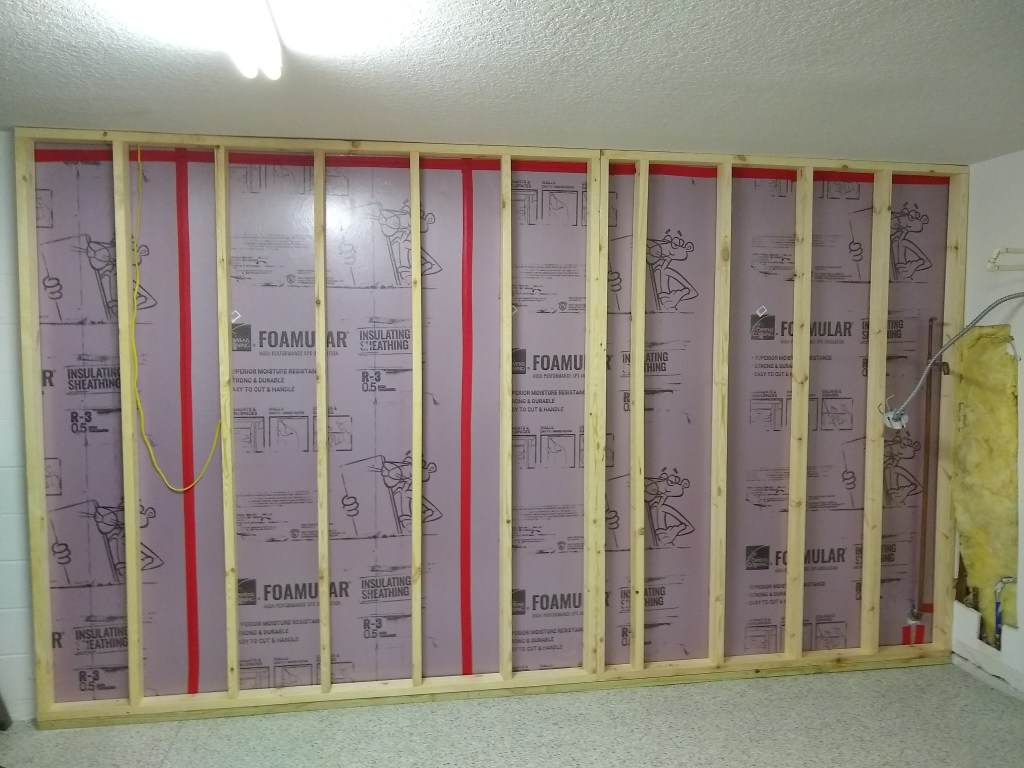
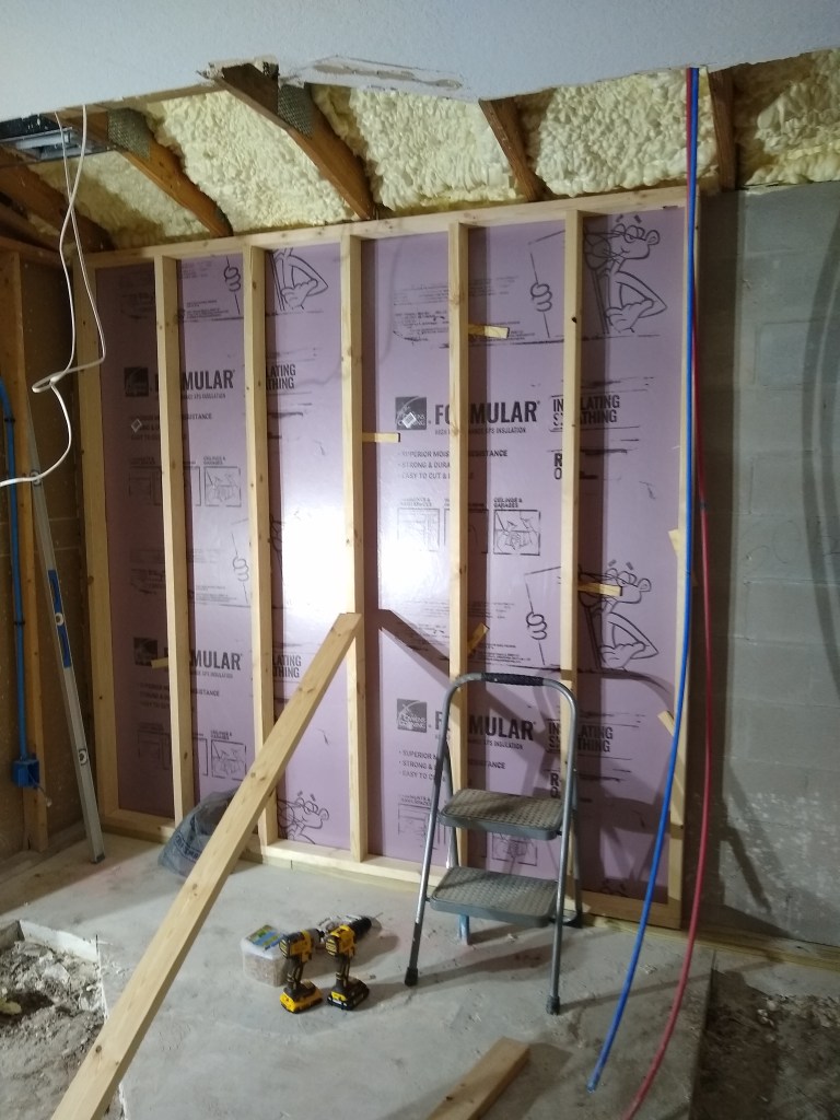
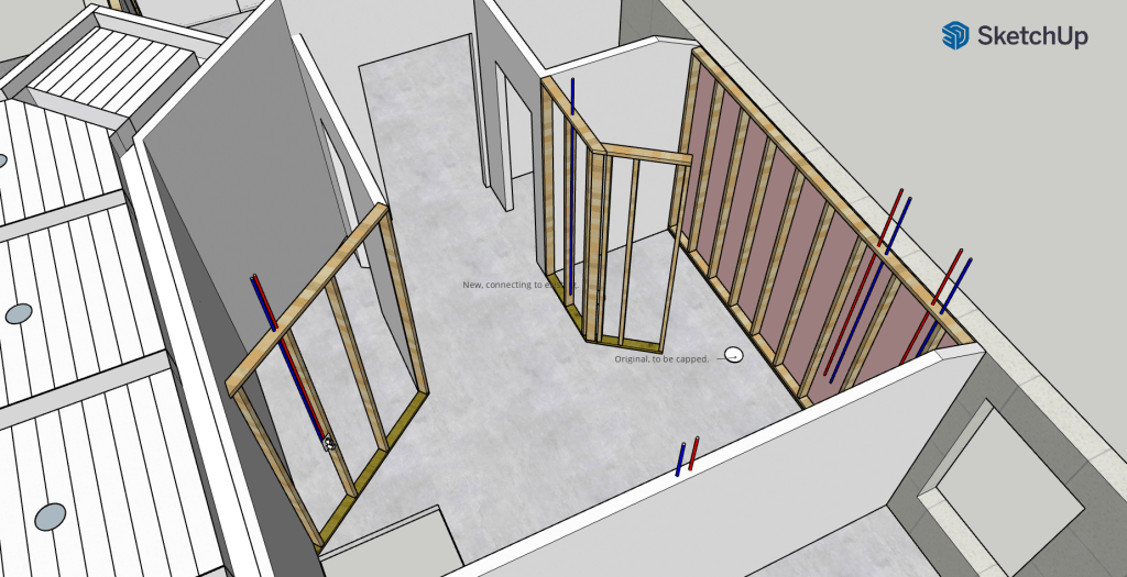
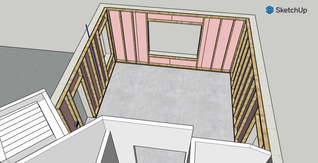
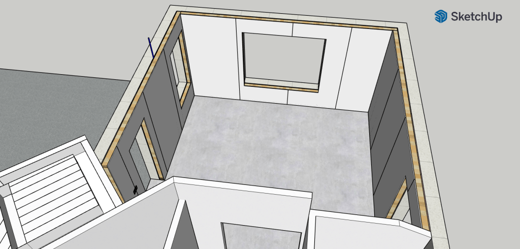
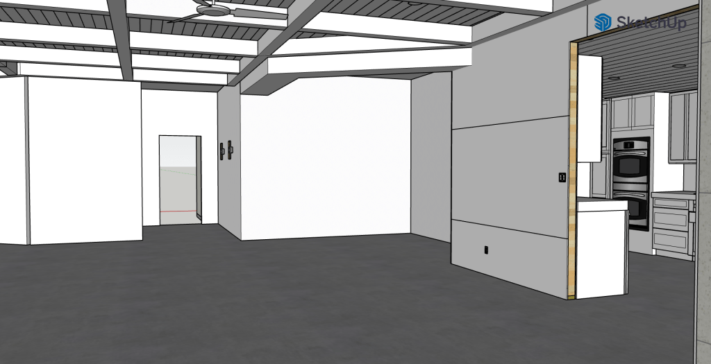
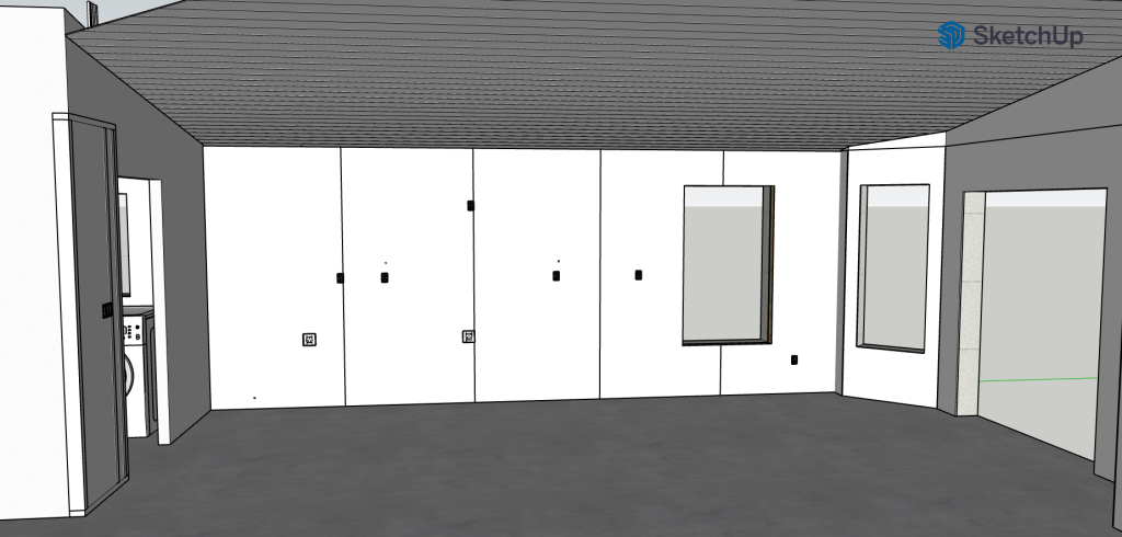
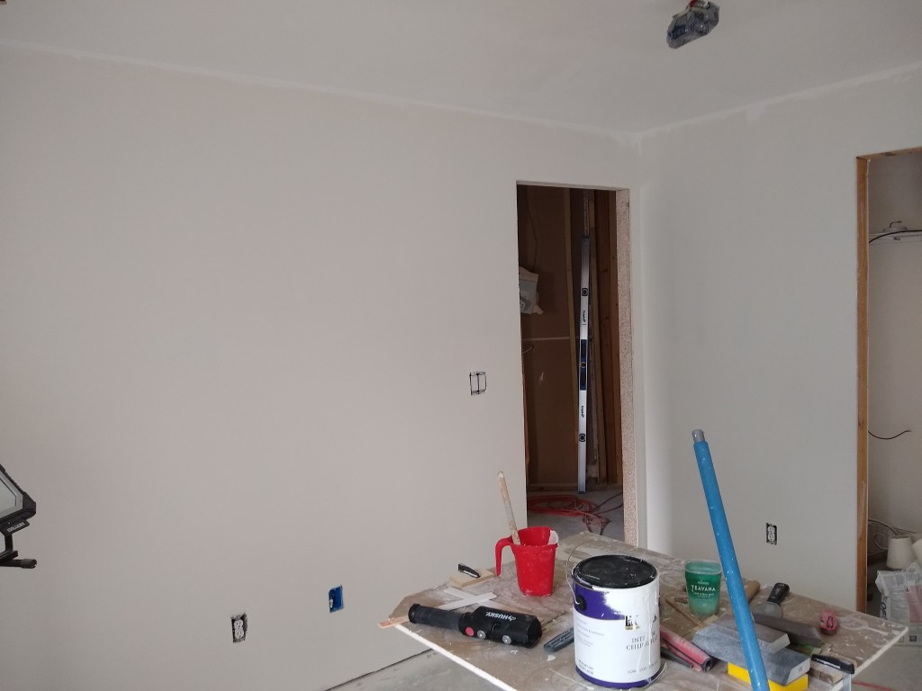
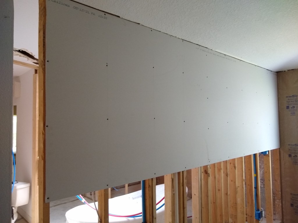
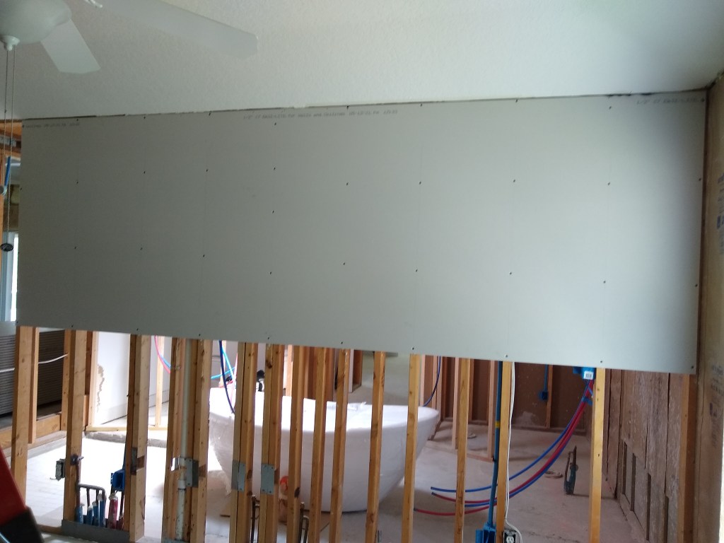
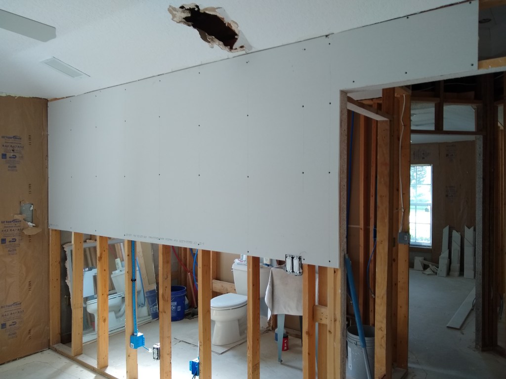
And here is the result. Note the new framing up top to connect to the existing part.

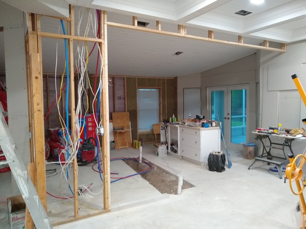
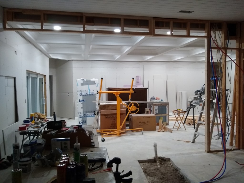
There is about 2 feet of the wall remaining, and that is there because we needed somewhere to put switches and water lines.

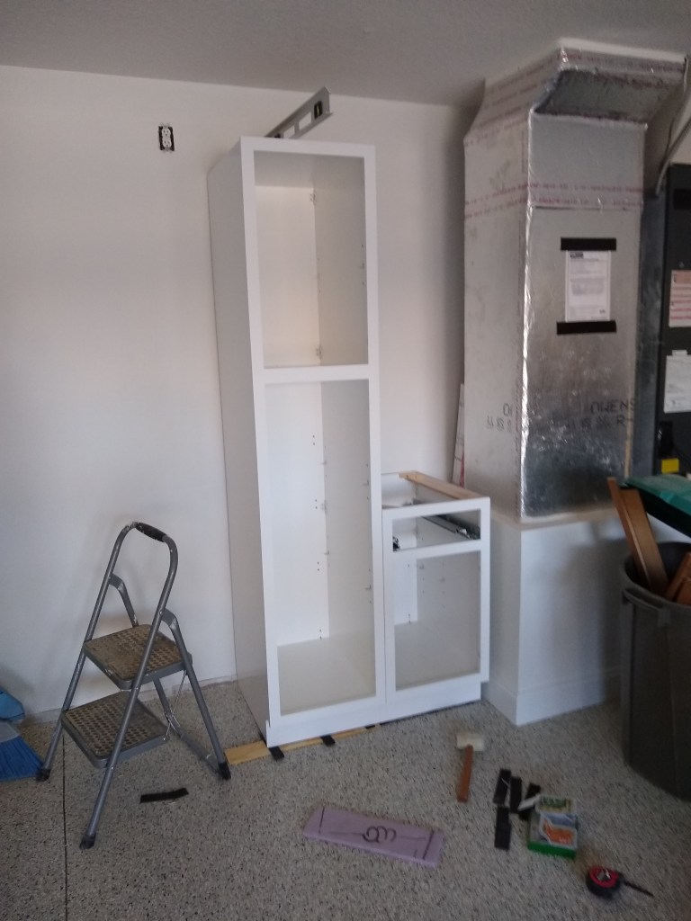
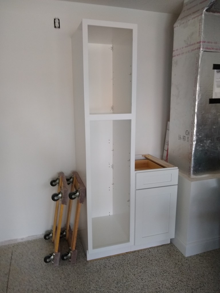
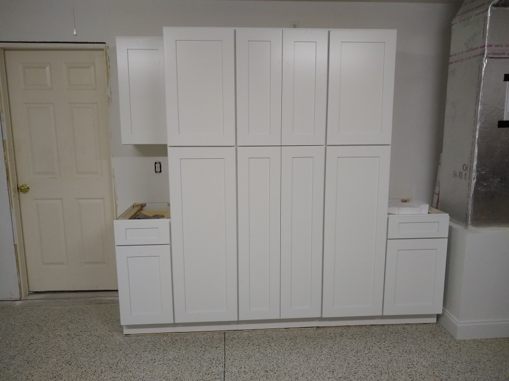
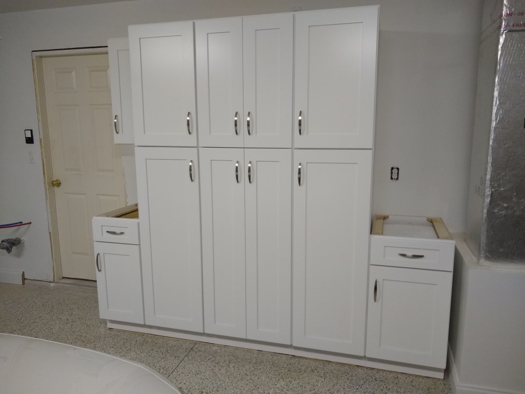
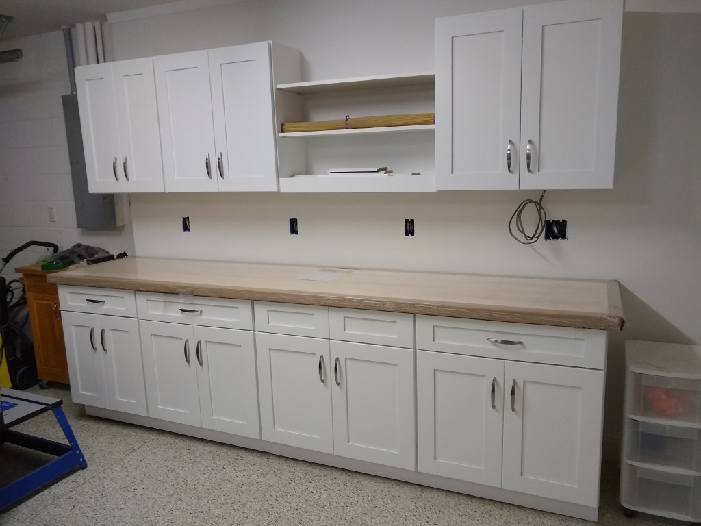
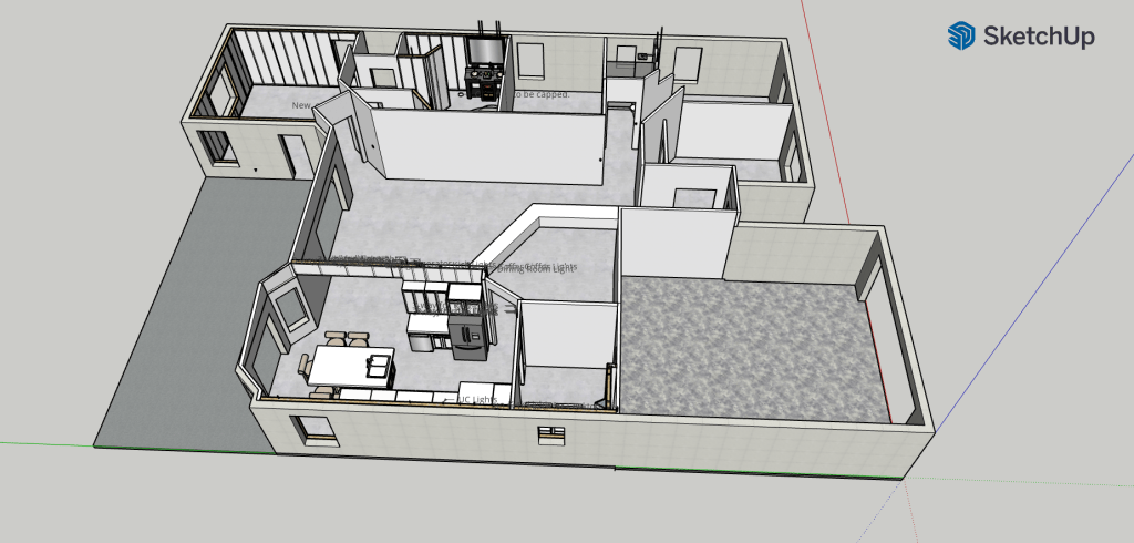
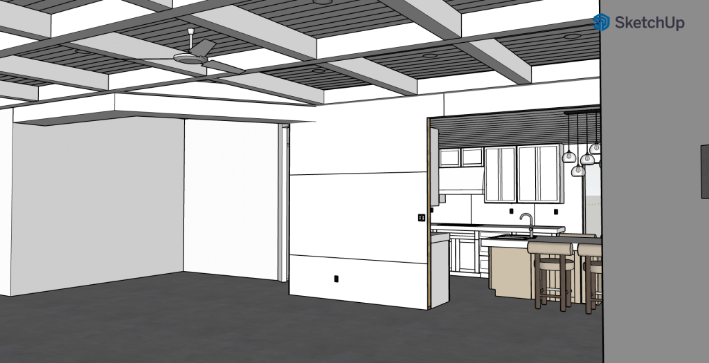
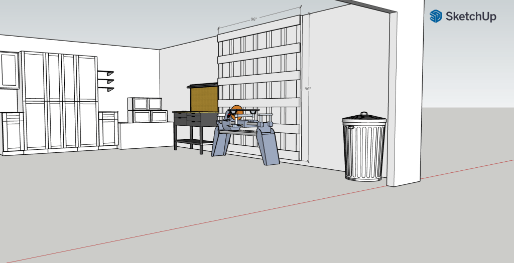
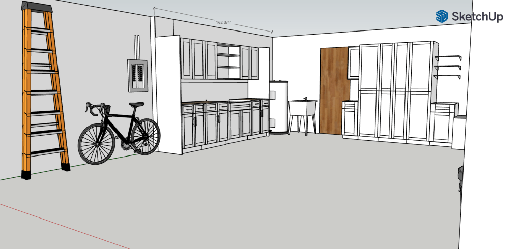
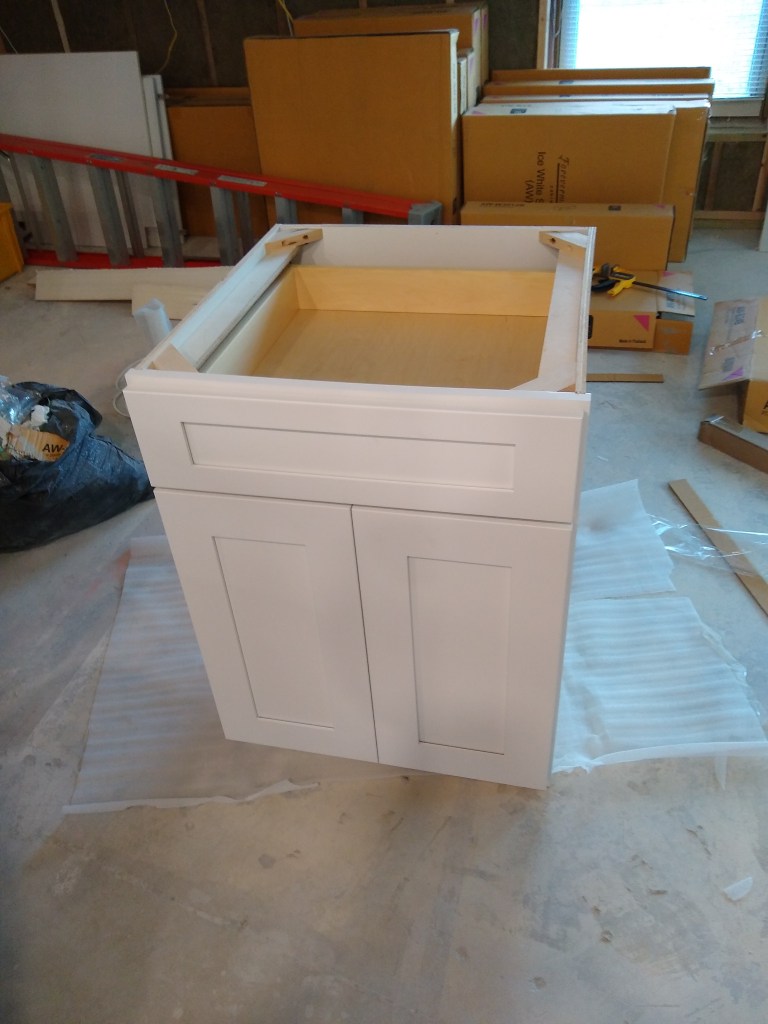
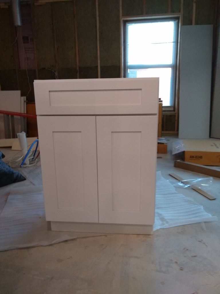
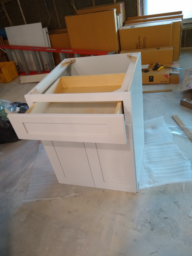
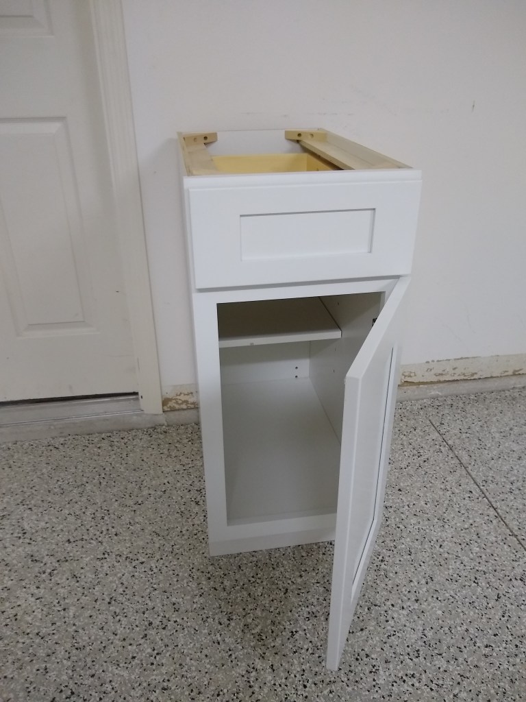
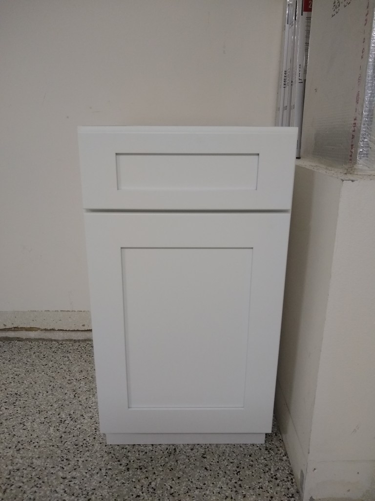
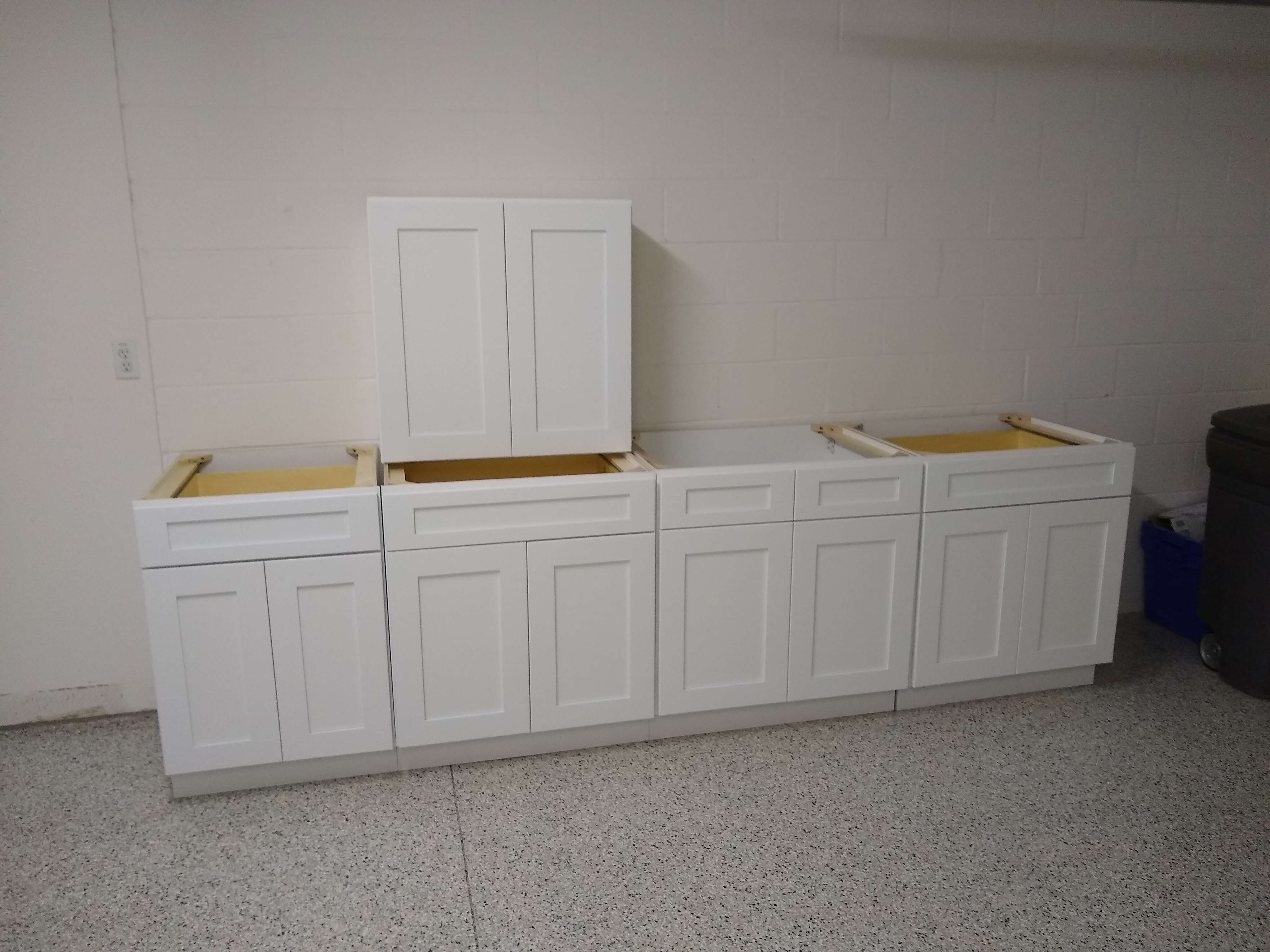
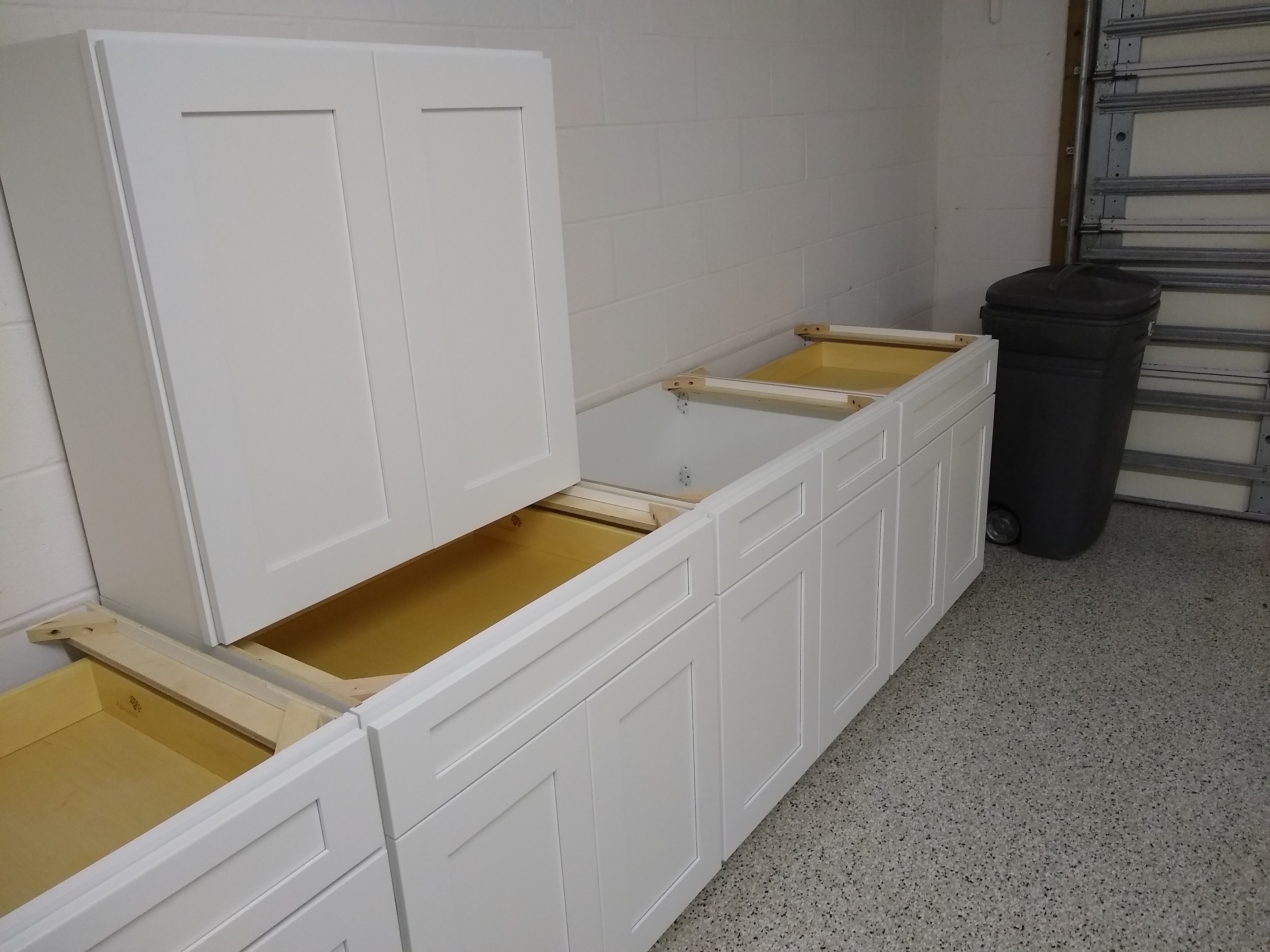
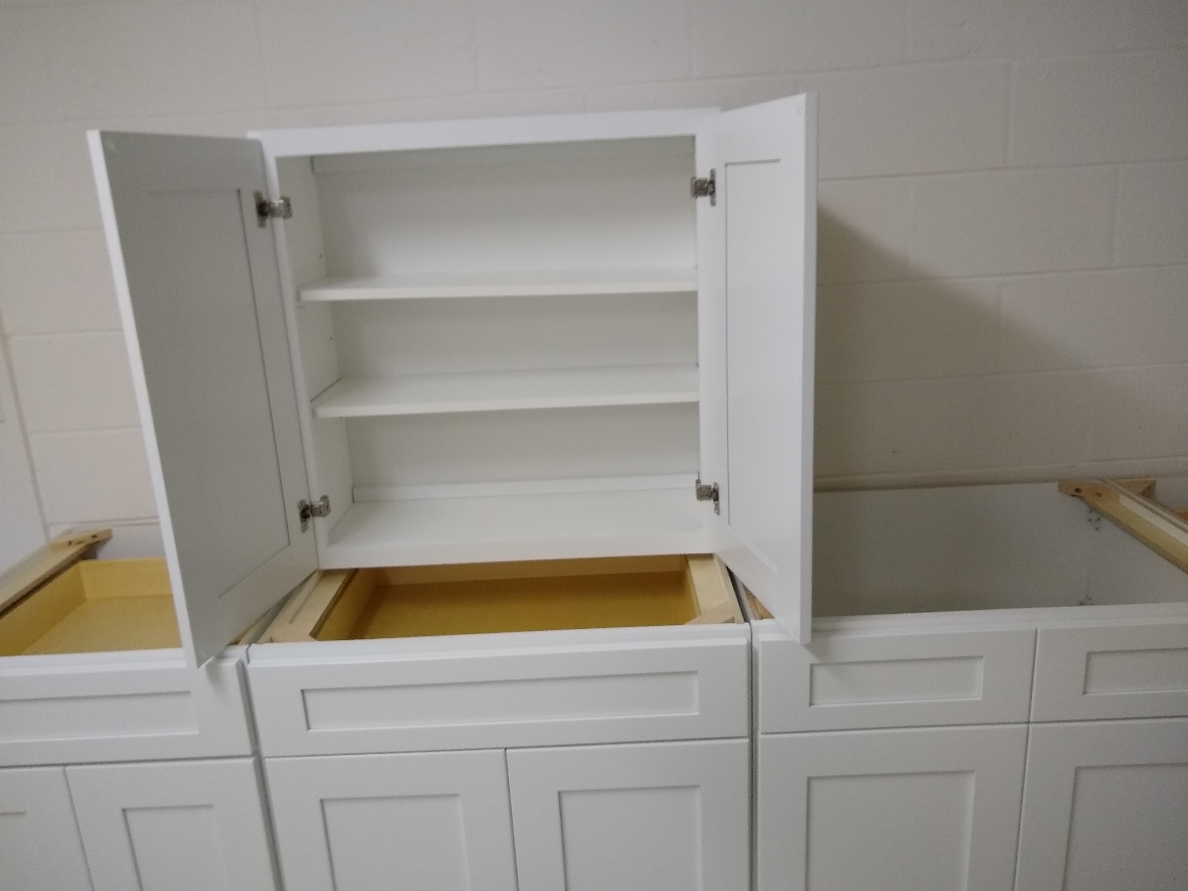
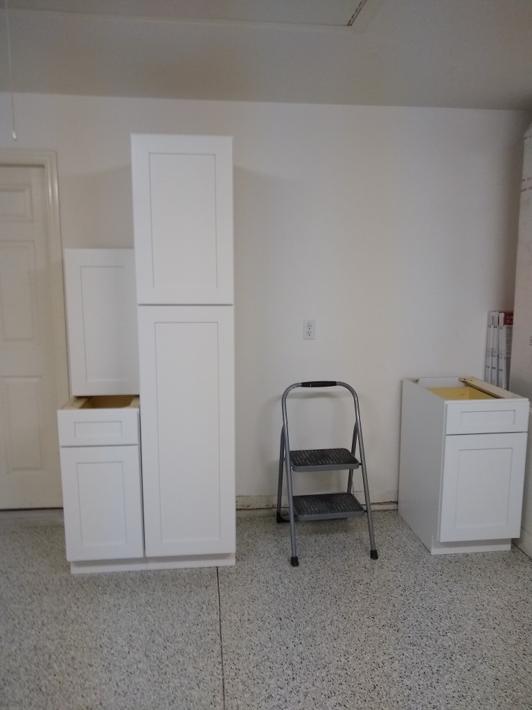
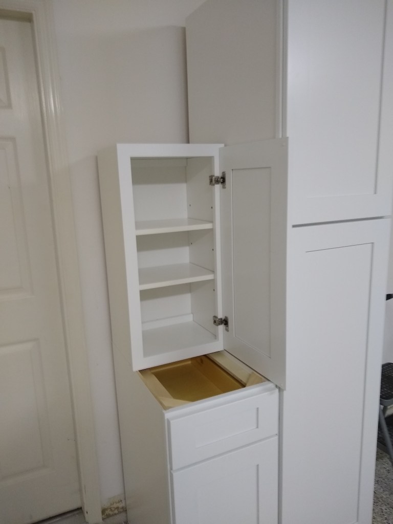
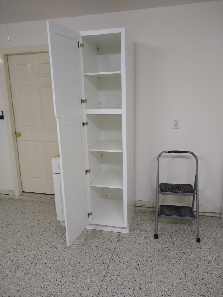
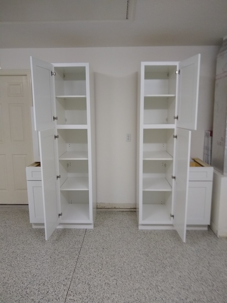
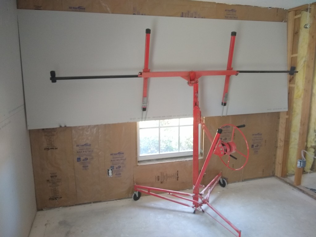
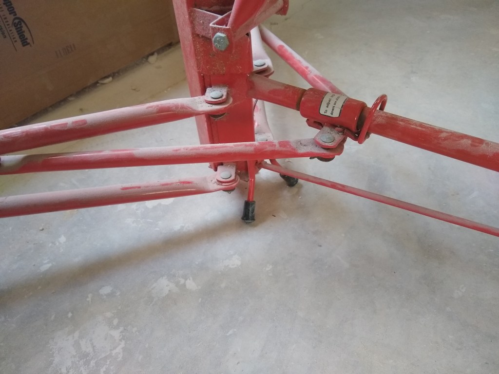
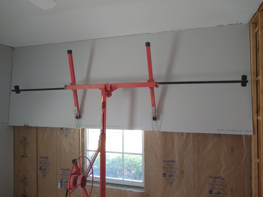
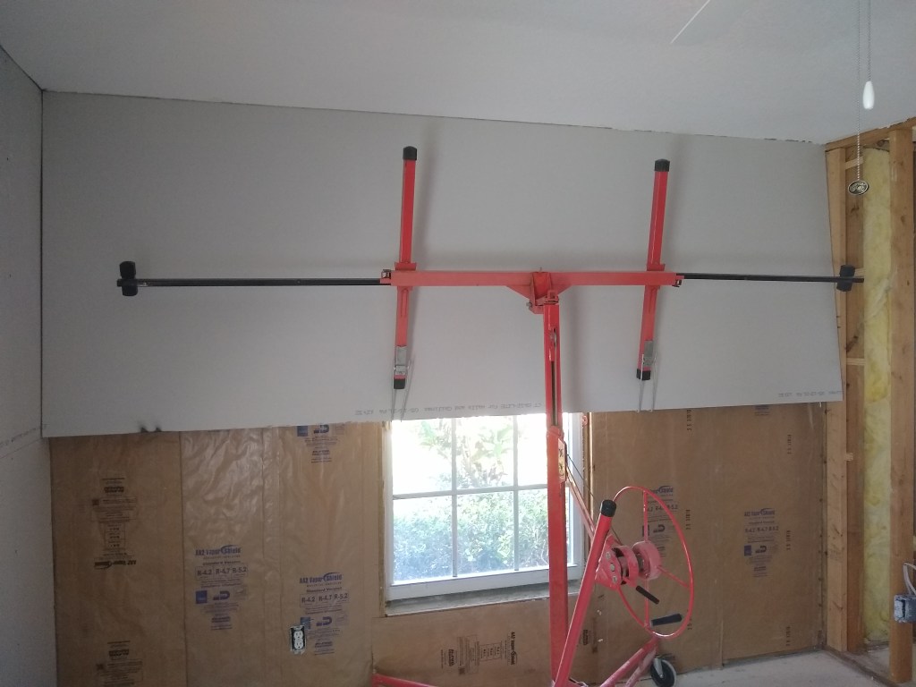
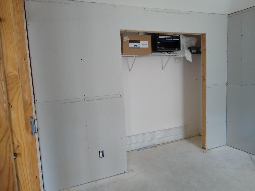
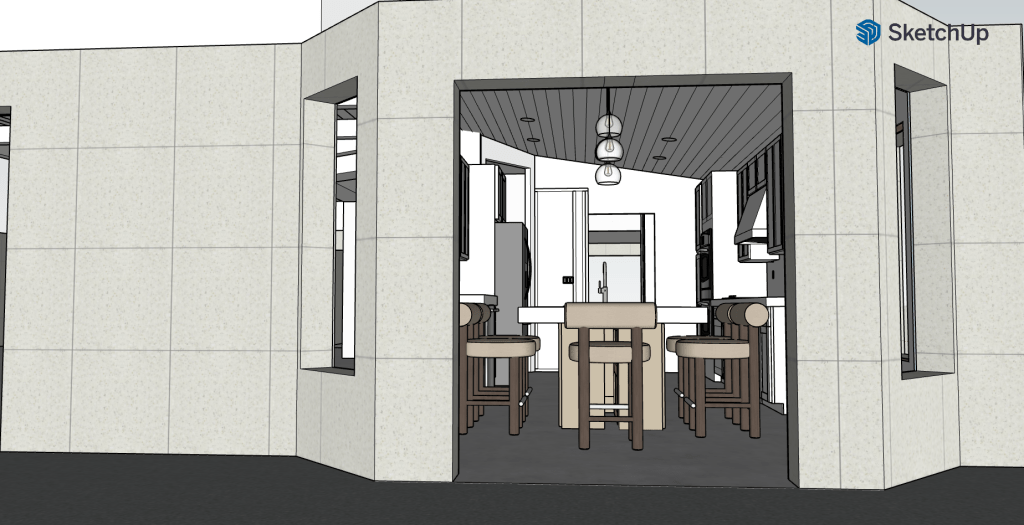
Here are some images of a mock-up of the kitchen island to give you a sense of how it sits in the space.

From the French Doors
From the Laundry Room
From the Great Room

After doing this mock-up, it became apparent that something was a bit off with respect to the dimensions. It was too big, leaving little room to maneuver around it at the ends. I discovered that there were measurement issues and spoke to Jennifer about it. The upshot is that I will reduce the size of the cabinets at either end to open things up a bit. No big deal. But you can get a sense from the images above how the island will sit in the kitchen.

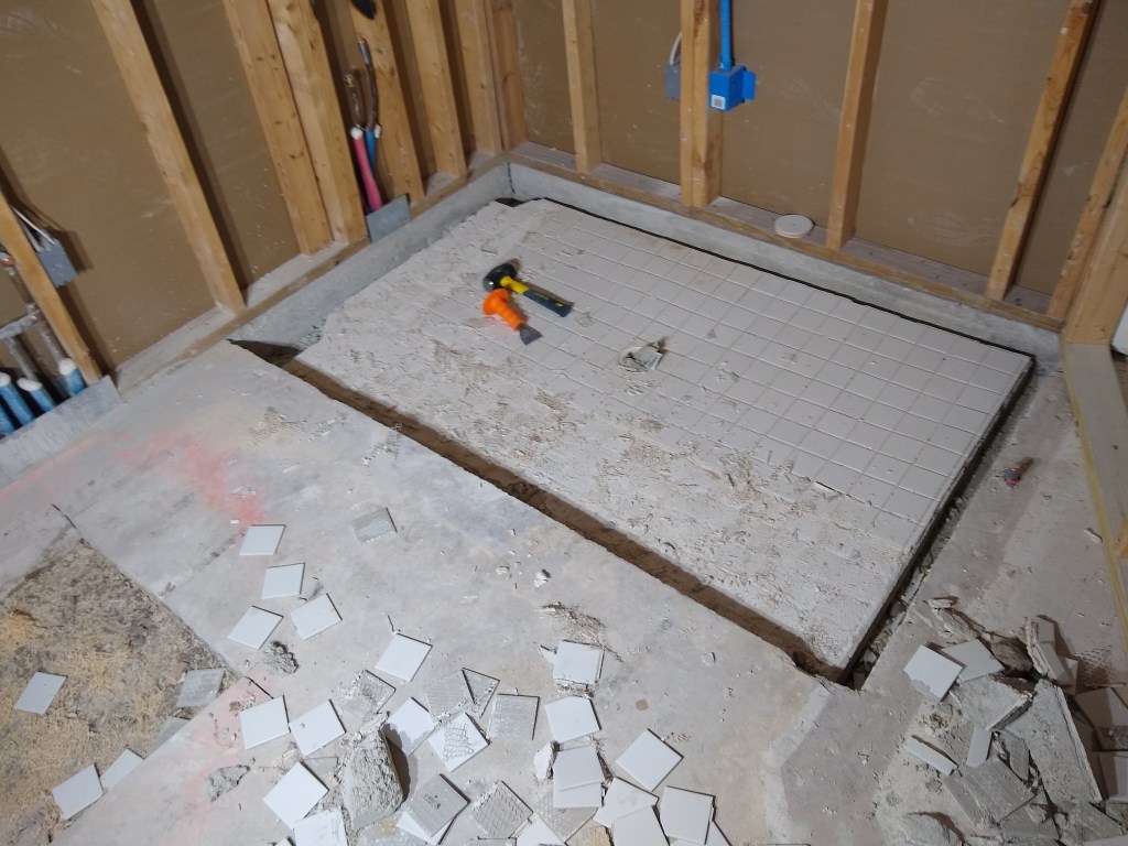
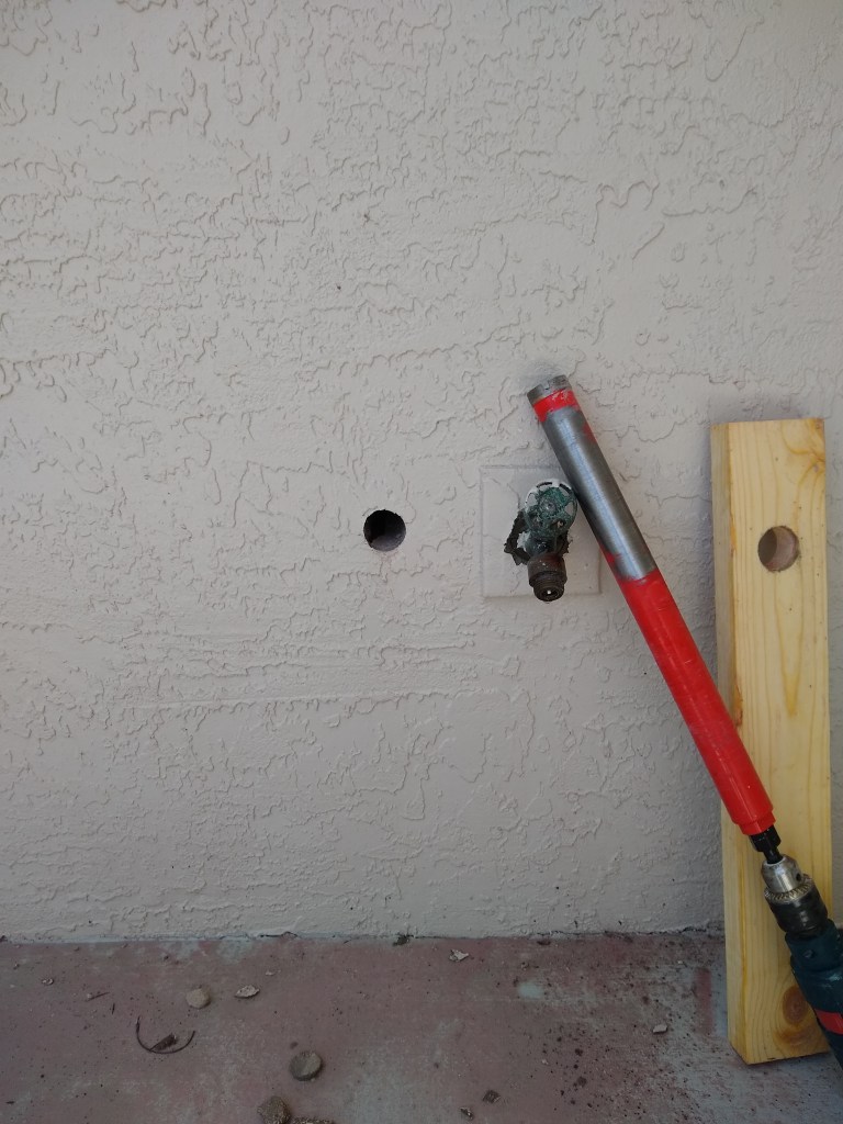
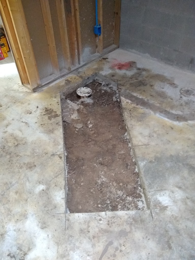
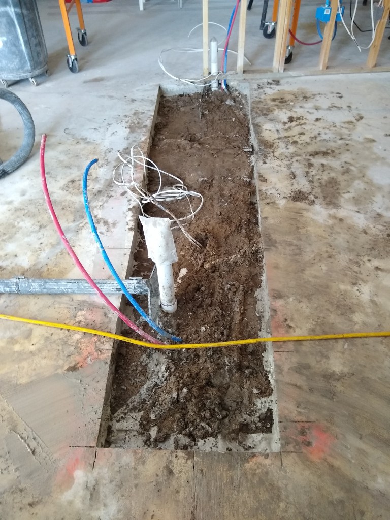
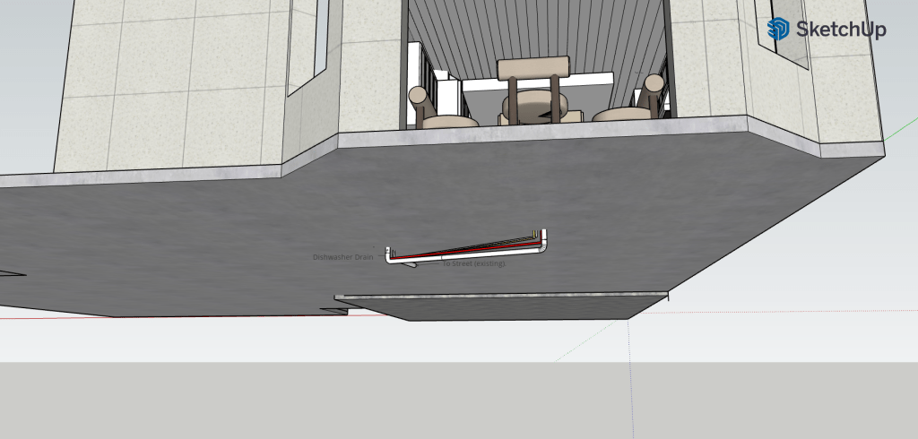
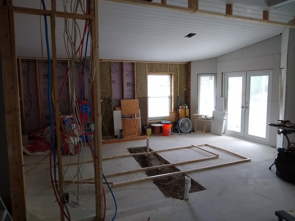
Although not planned that way, the existing trench is well positioned and will line up nicely with where the sink will go. I’ll just have to move the drain in by a couple of feet. However, to accommodate the supply lines, a new trench will have to be cut to connect from the small wall where the electrical and plumbing lines are to the existing trench. Before getting to that, though, I relocated the water line for the ice maker in the refrigerator.

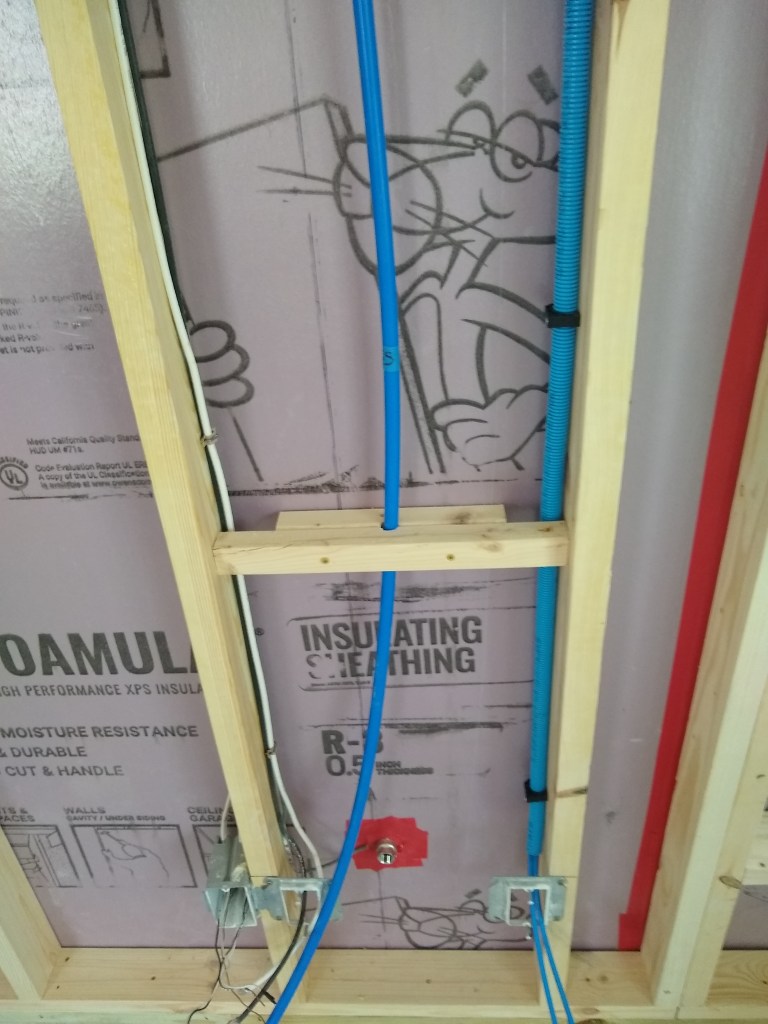
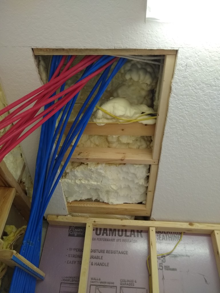
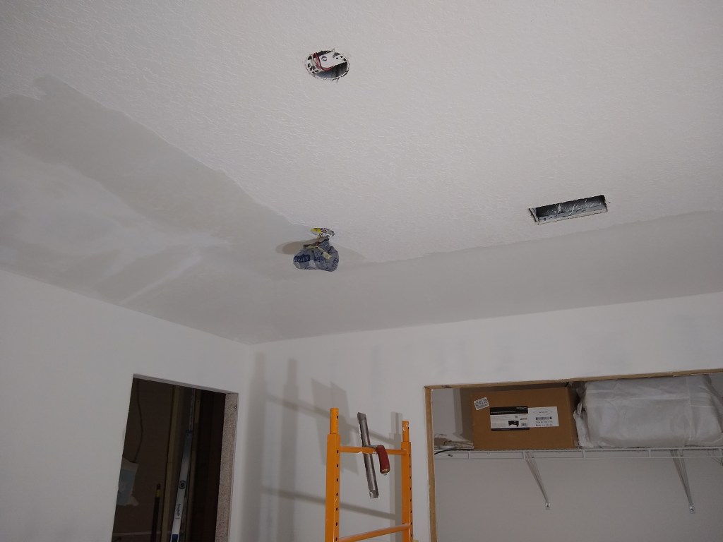
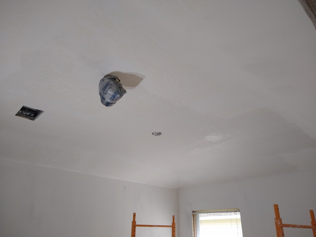
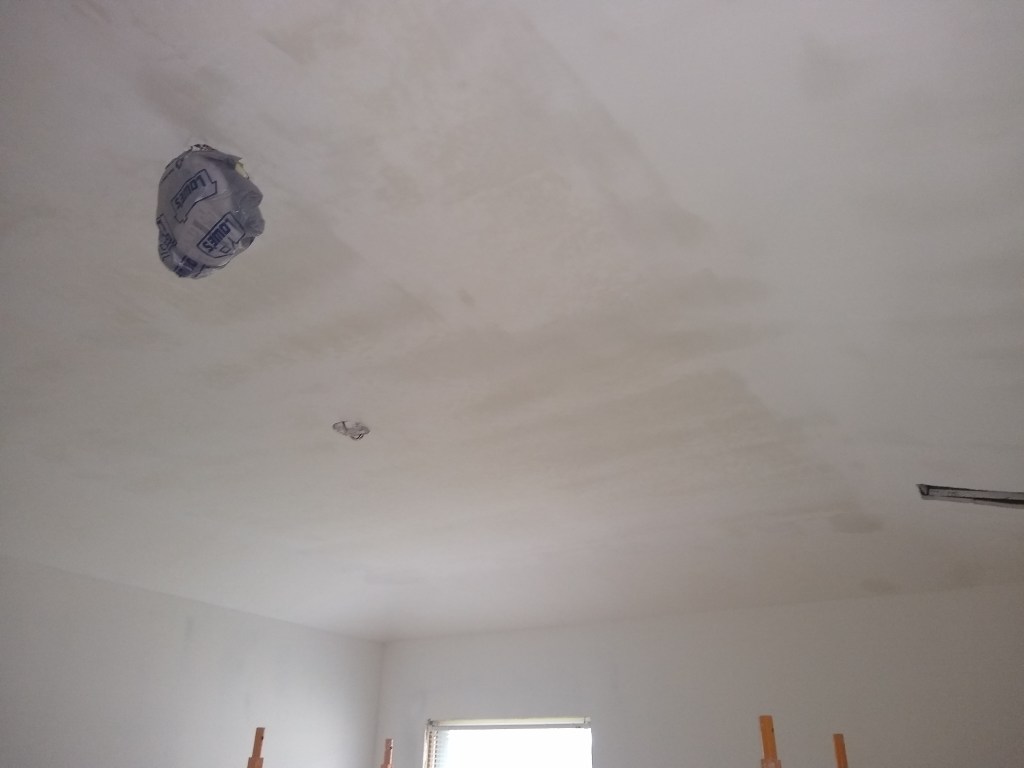
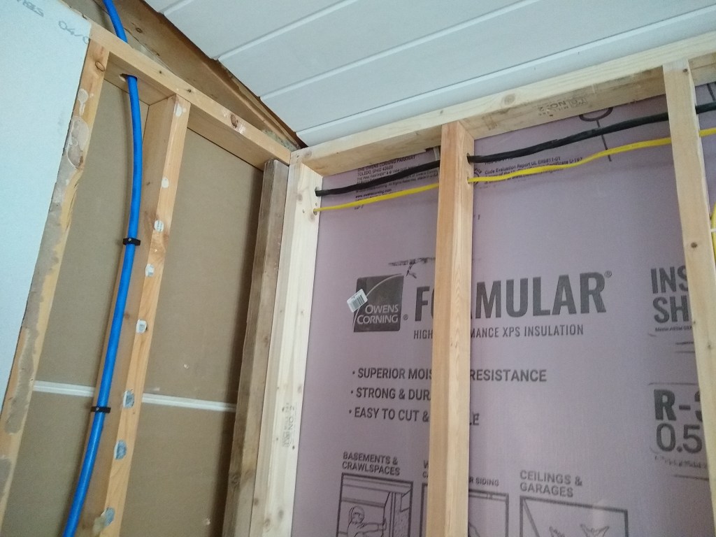
I moved the water line so that it enters the kitchen from the ceiling within the wall that separates the kitchen from the laundry room. I would have preferred to send the line most of the way above the ceiling and bring it down directly above the refrigerator, but with the spray foam insulation and the sloping ceiling, there was no way I could access that area. It was tough enough bringing the line down here. Very tight quarters. I was laid out flat on my stomach to reach the opening I drilled.

Ice Maker Water Line coming down from the Ceiling

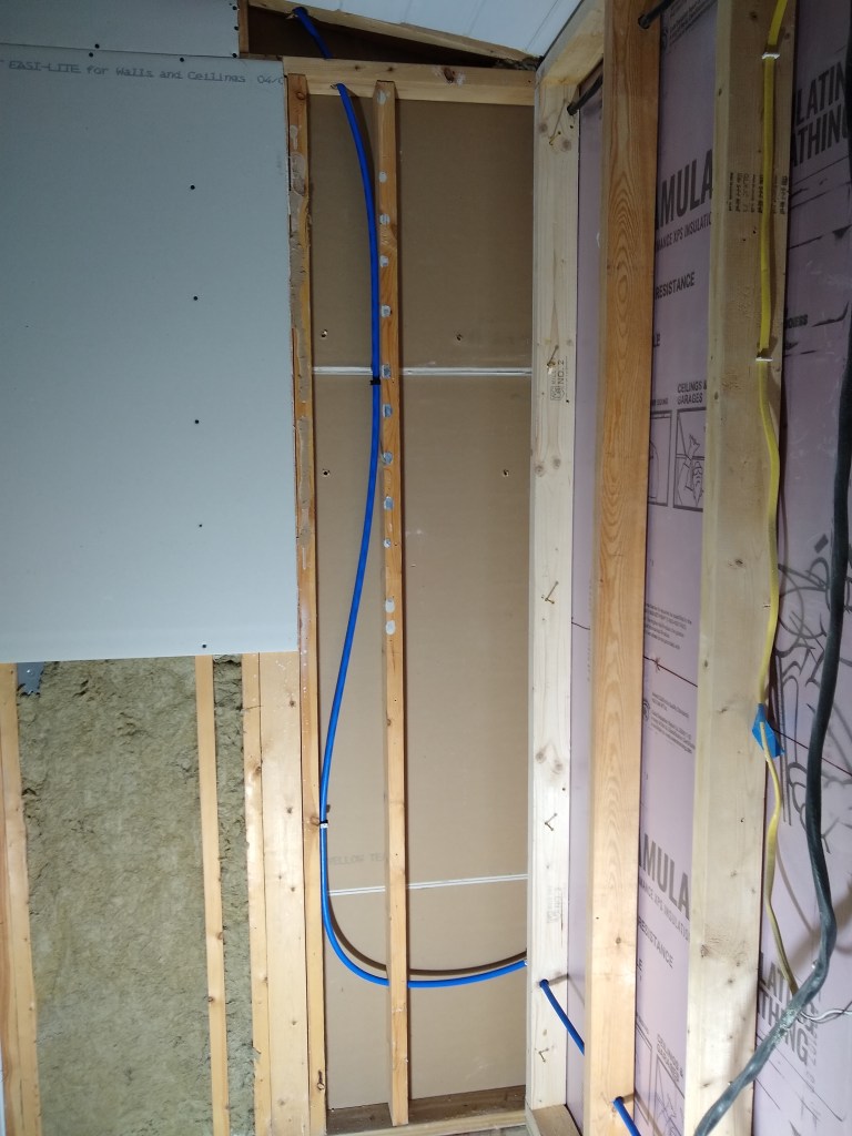
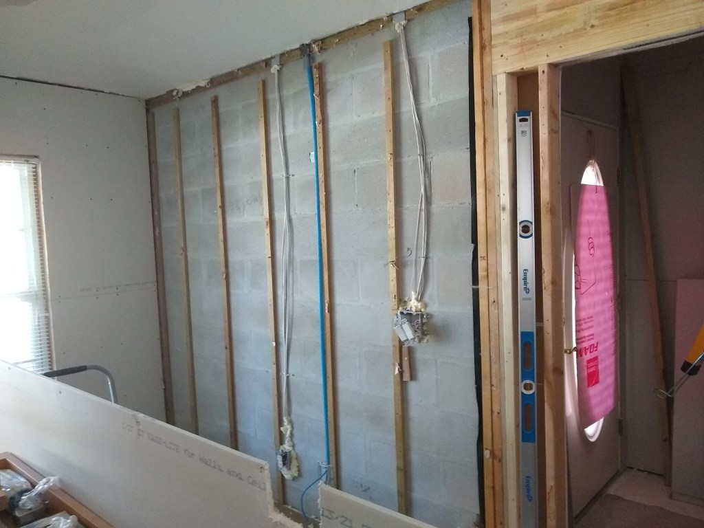
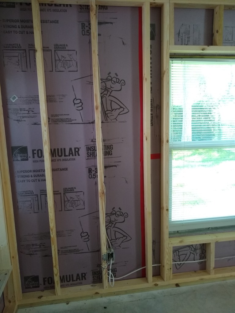
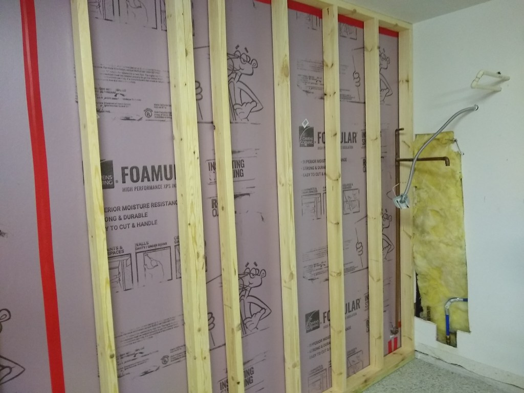
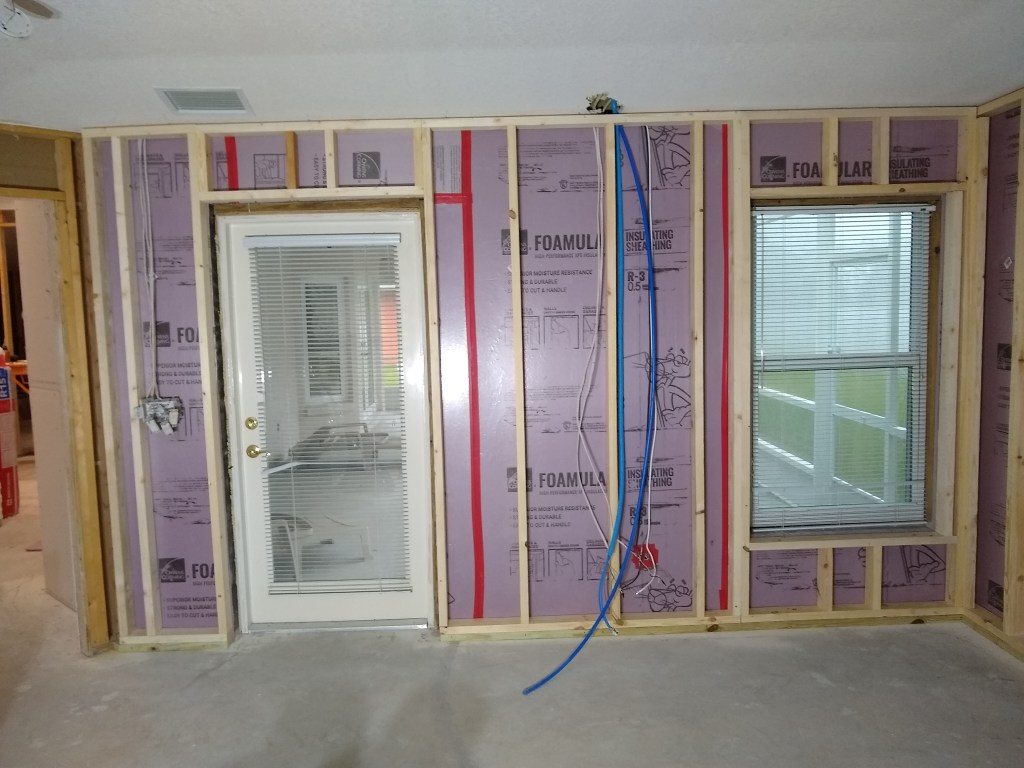
Once the line was pulled down I had to extend it almost the entire distance along the east wall of the kitchen, which was easy enough, just a lot of holes to drill.

Ice Maker Water line extended to Refrigerator location

This required a 90 degree connection; the only connection along the span, which isn’t bad. I had to remove the vertical 2×4 that was installed as a nailer so that I could get access. When I put the nailer back in place (you can see it in the pic above), I cut out a notch to make room for the connection.

90 degree Connection

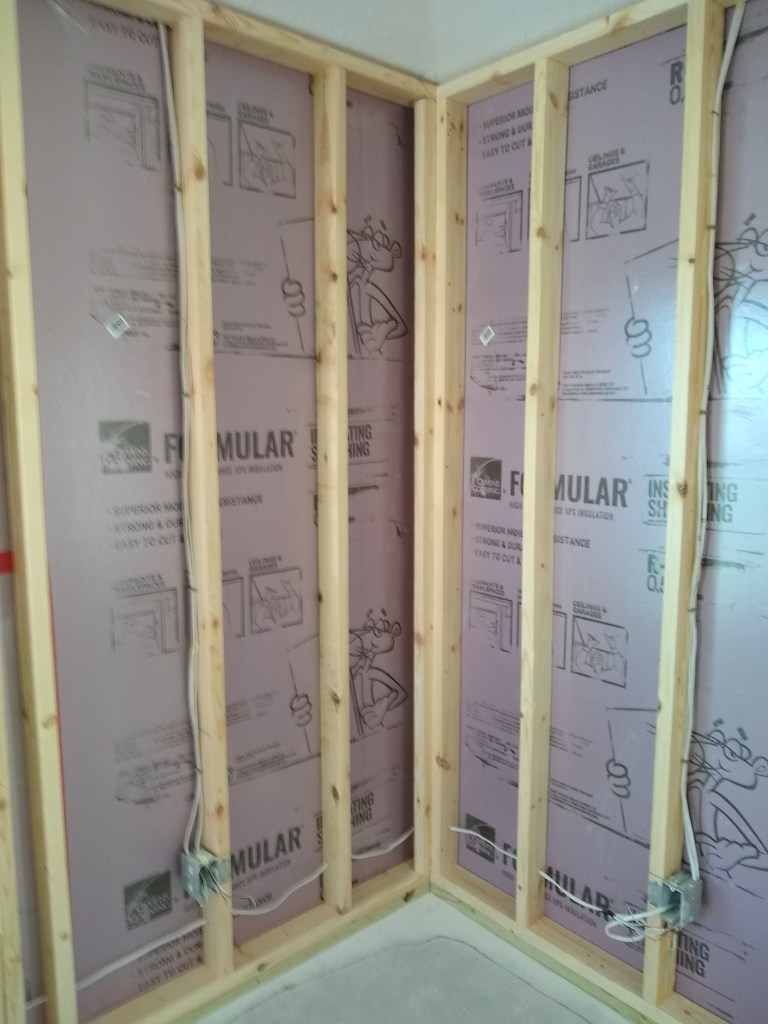
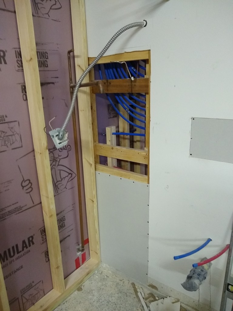
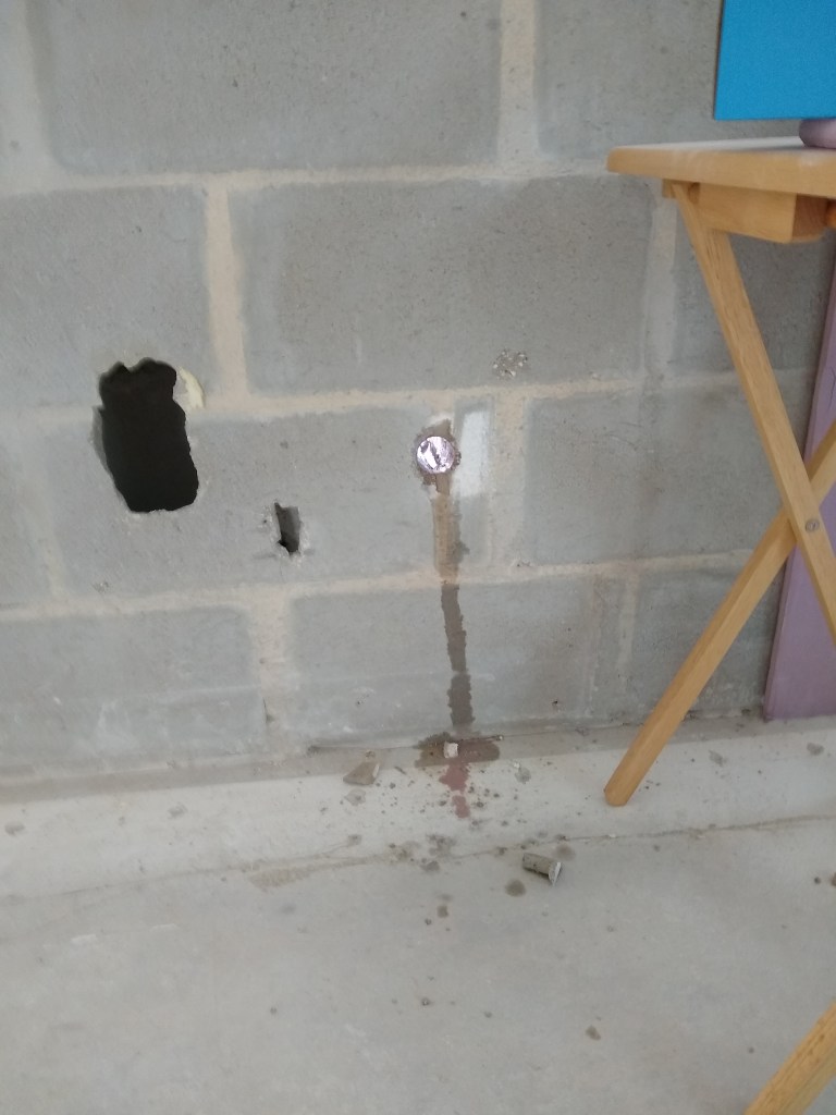
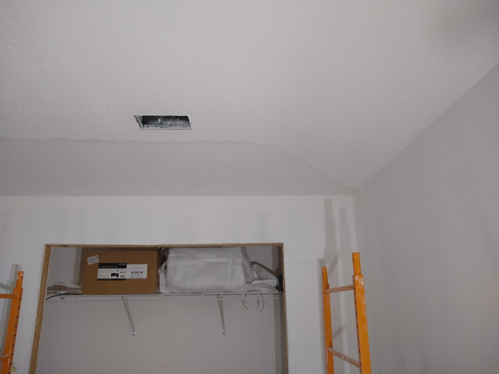
I had to do something similar with the electrical connection for the refrigerator. Like the water line, I couldn’t simply drop the wire down from the ceiling at it’s destination due to the spray foam insulation being in the way, so I routed it through the plumbing closet in the laundry room.

Fridge Junction Box in Plumbing Closet

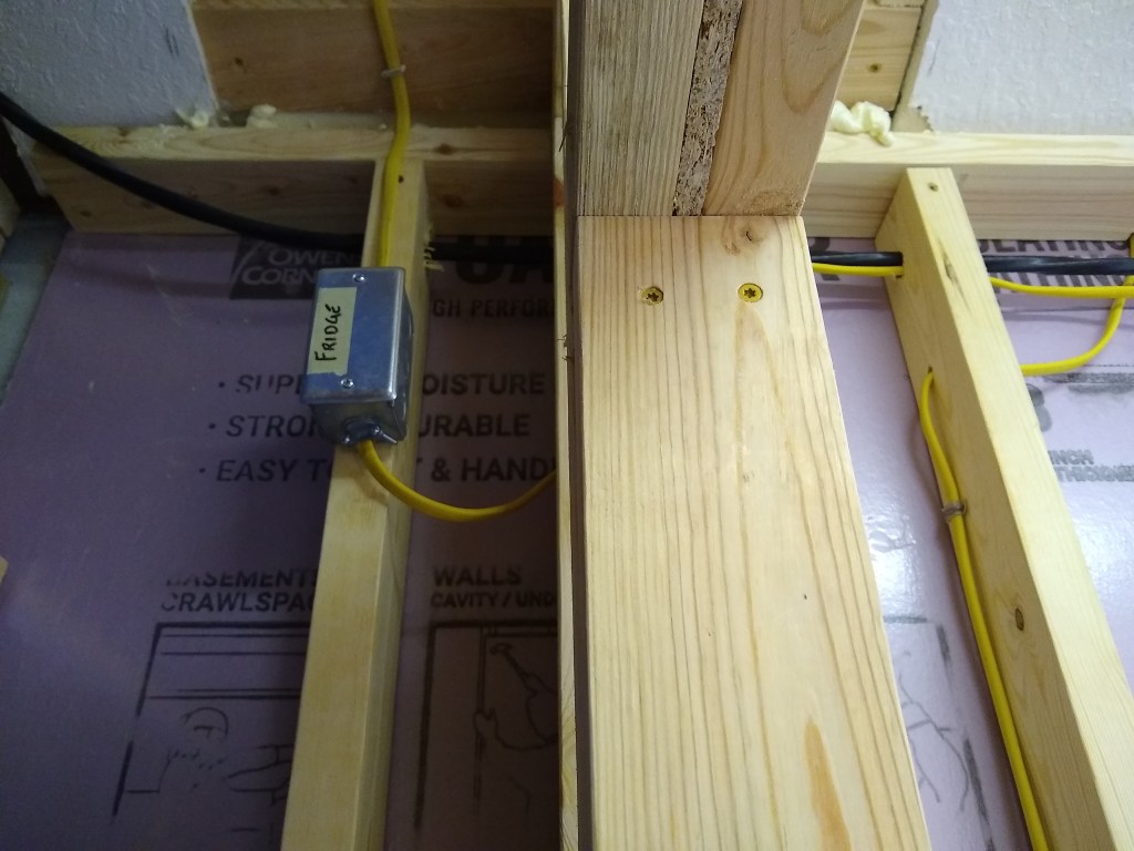
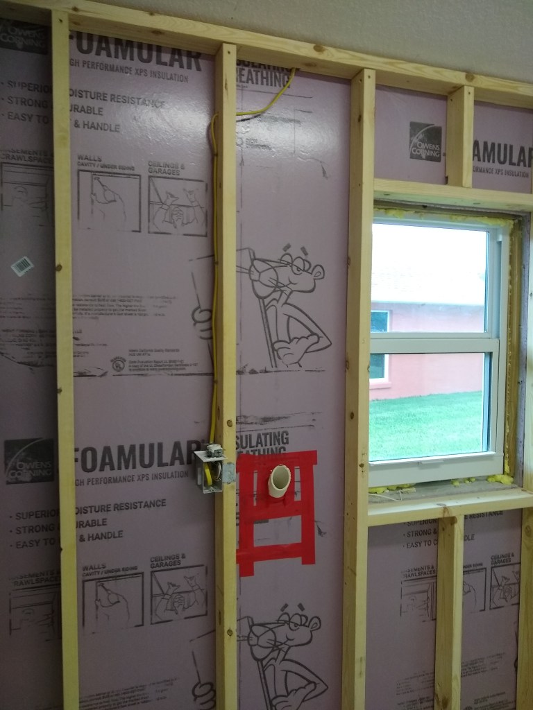
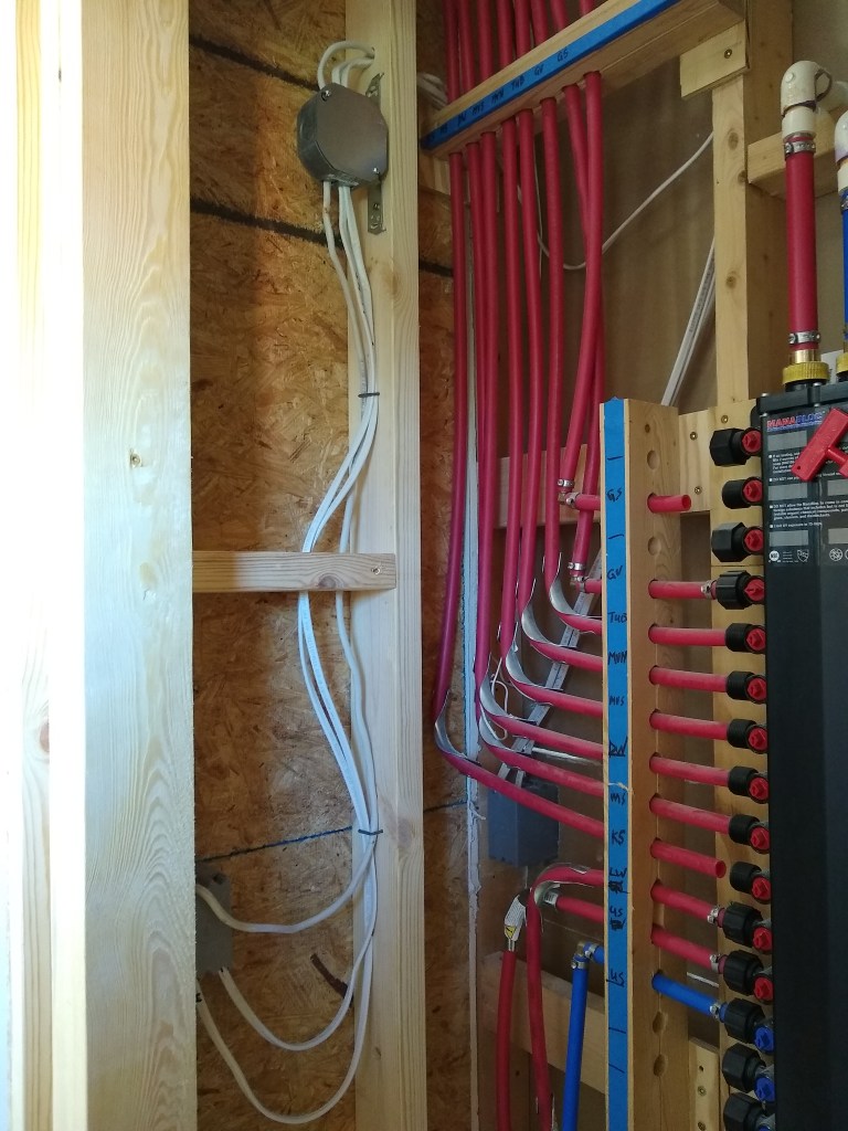
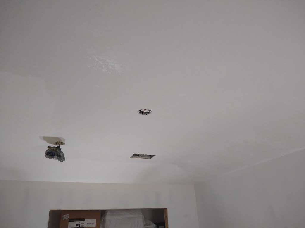
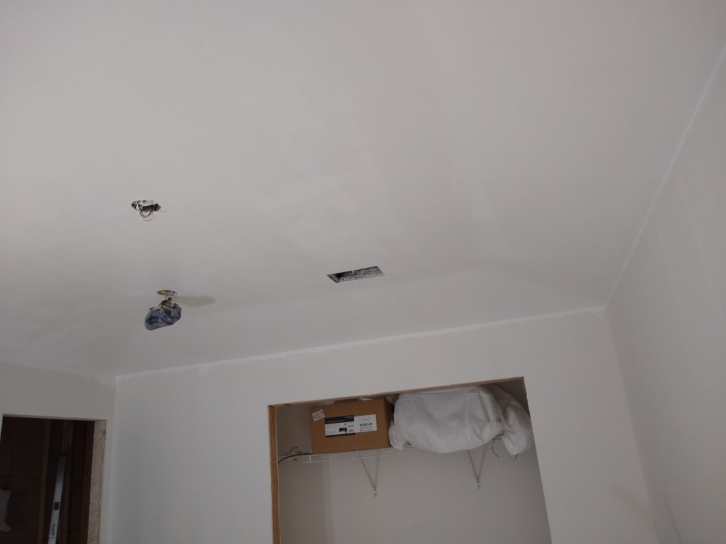
Since the length of wire from the original fridge location was not long enough to reach the new location, a junction box was needed to splice in a length of wire sufficient to finish the journey. The wire exiting the junction box followed the path of the cooktop wire (black) until the dividing wall, where I had to drill a separate hole because it was just too tight from that point on. Below you see it emerging from the laundry room into the kitchen.

Fridge Wire emerges from Laundry Room

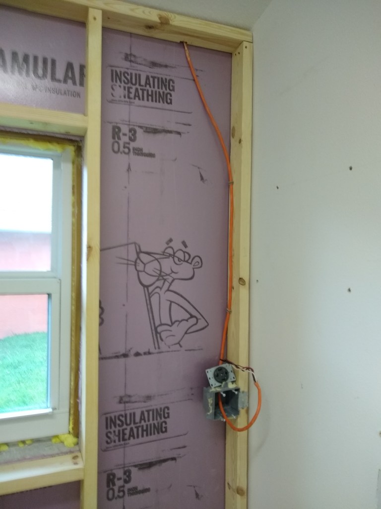
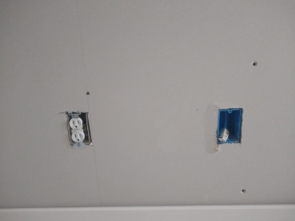
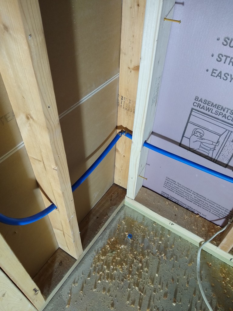
And finally to the fridge location, shown below beside the end of the blue water line. I had just enough wire to reach (I was trying to avoid having to buy more). It was too close, actually. I ended up installing the outlet box a bit higher than I normally would just to make sure I had enough to play with when it was time to install the receptacle. The location of the outlet is not critical because it will be hidden behind the fridge, so I chose to take advantage of that rather than make the final hookup more finicky than it needed to be.

Refrigerator Wiring

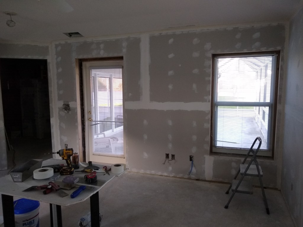
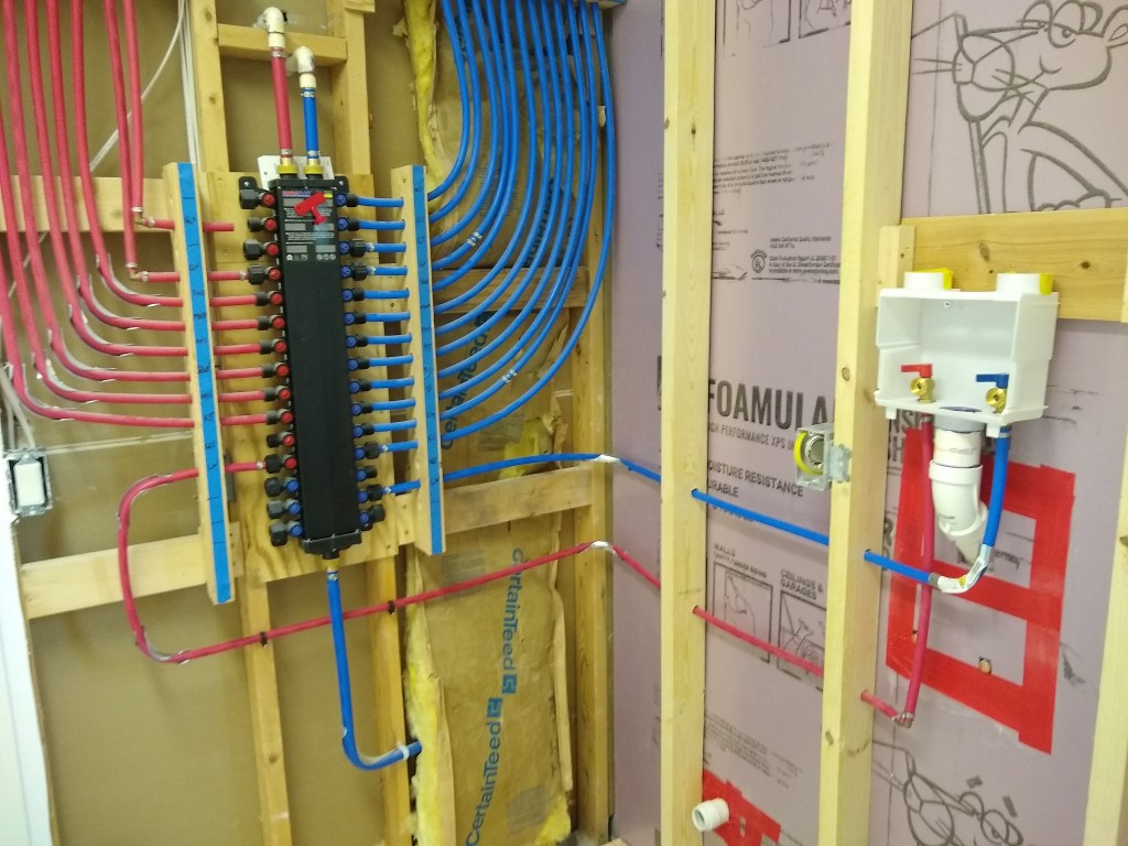
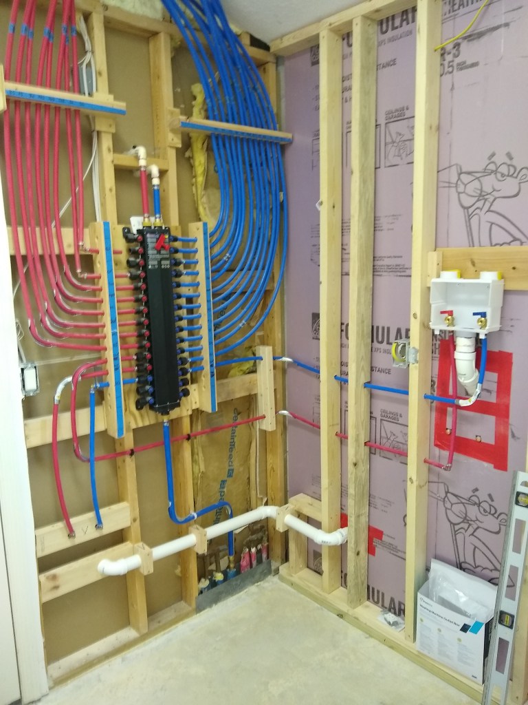
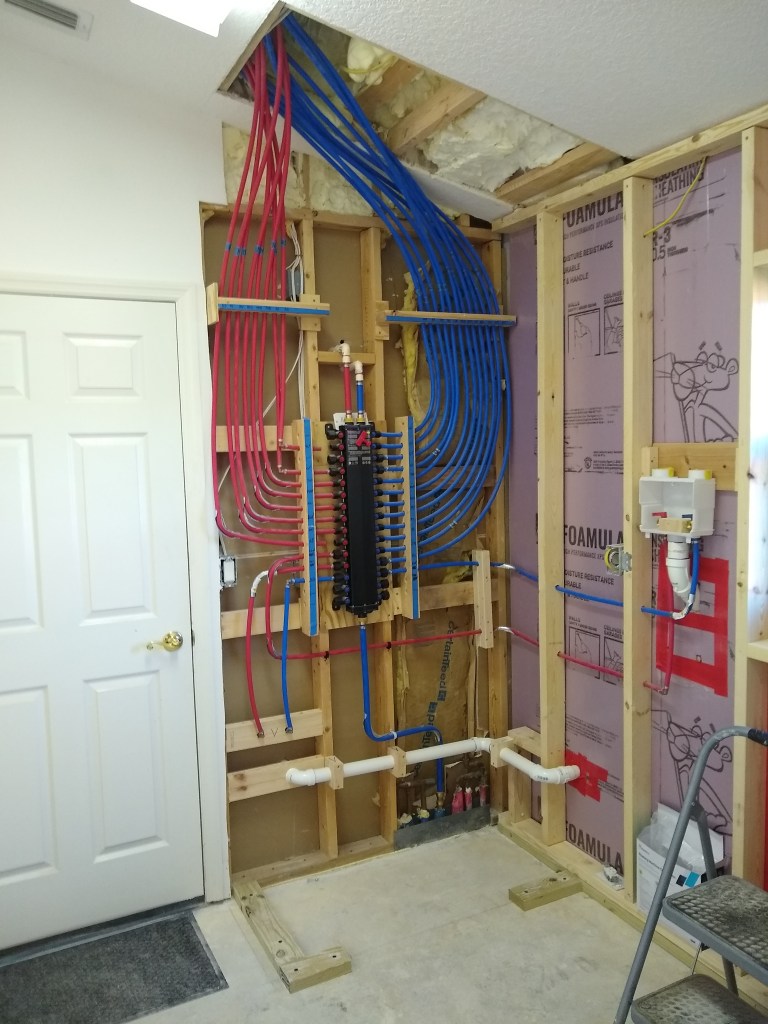
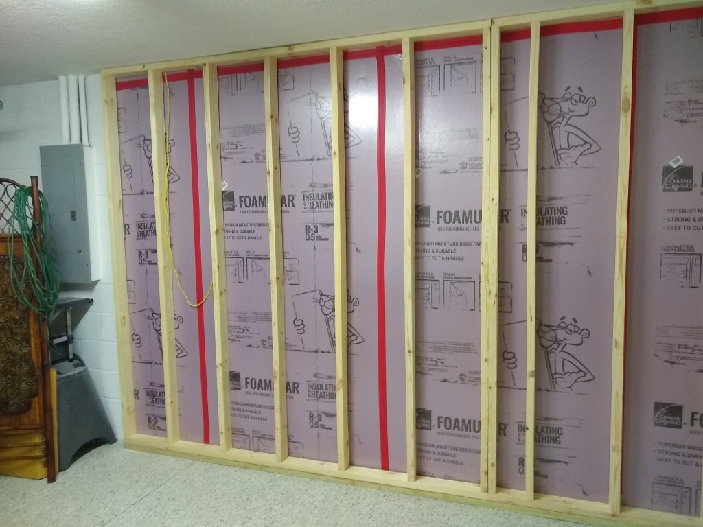
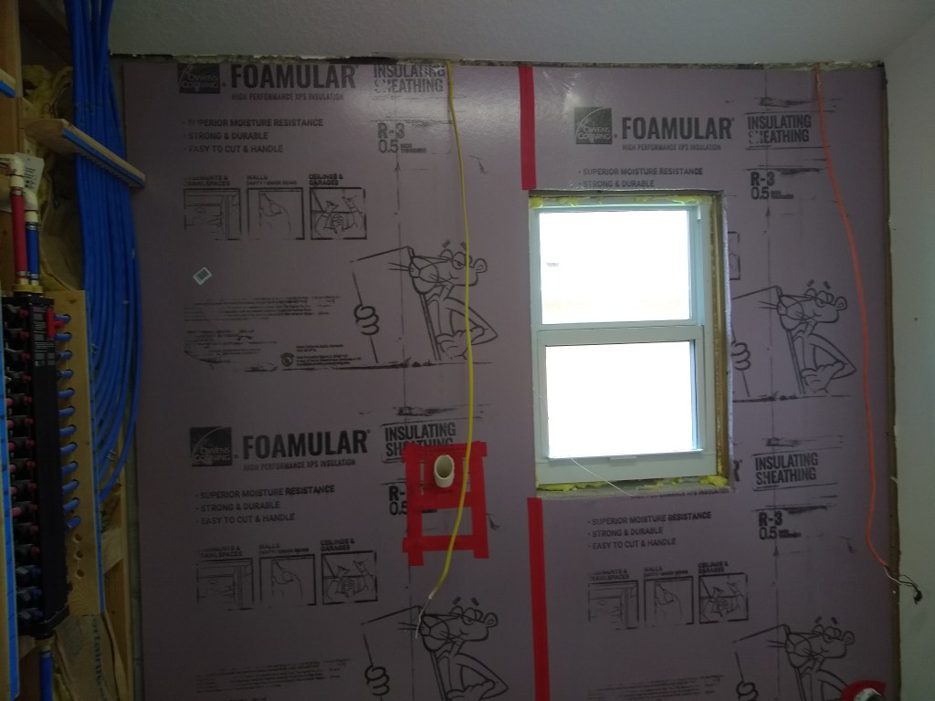
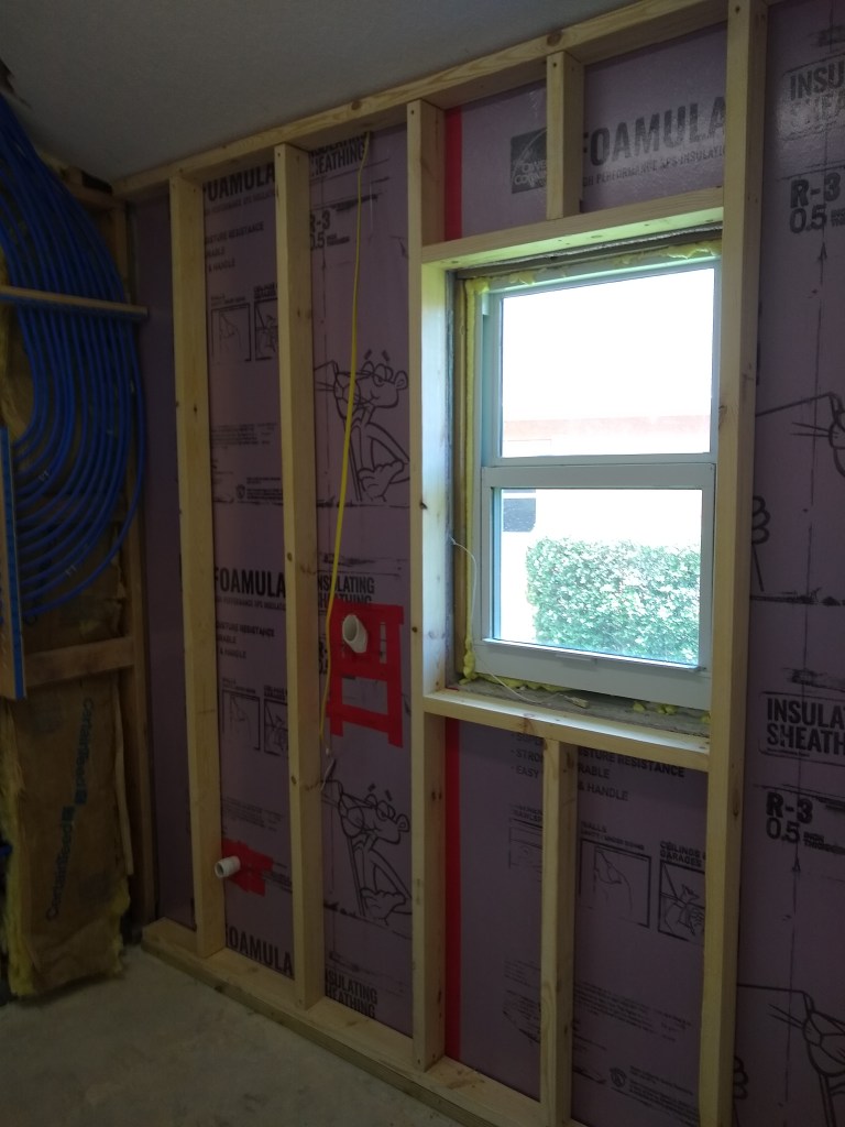
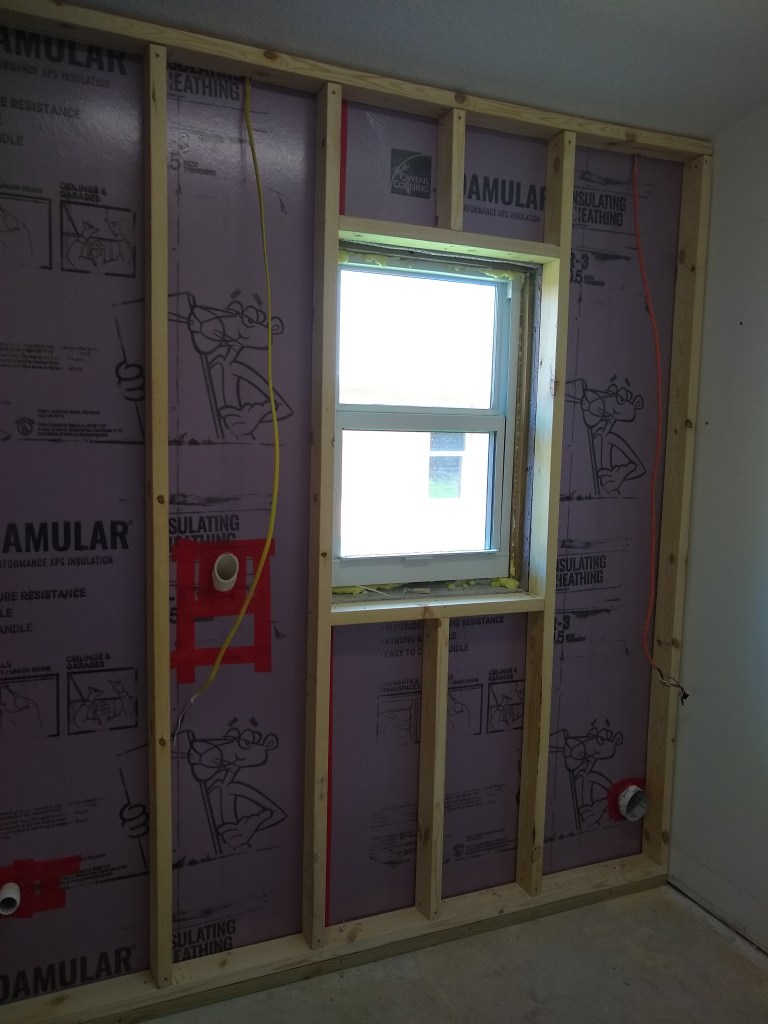
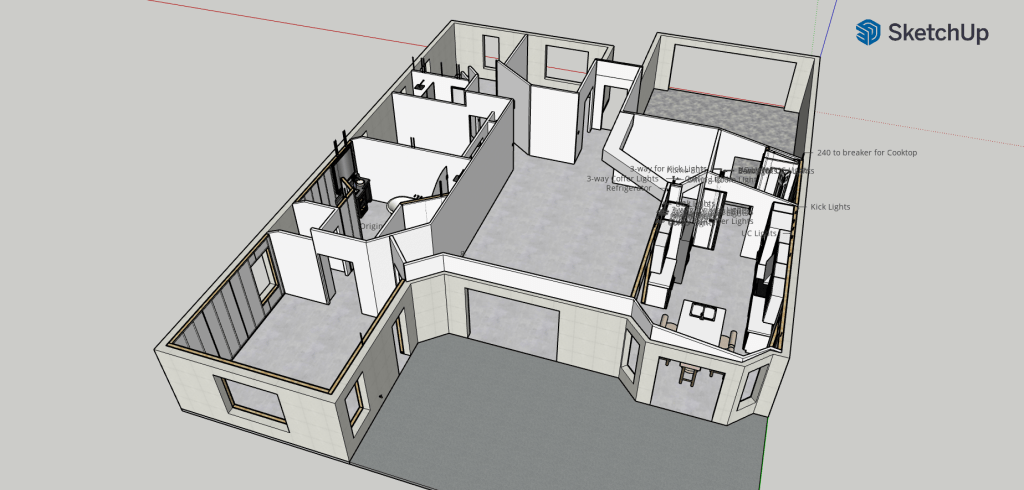
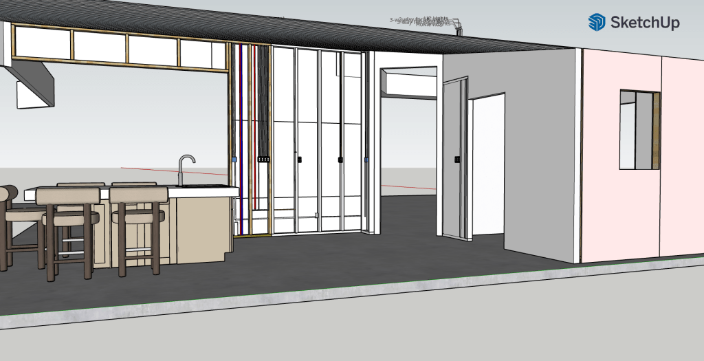
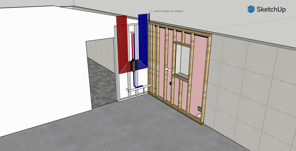
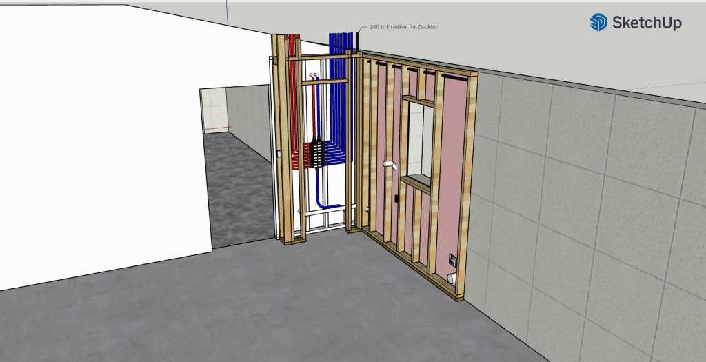
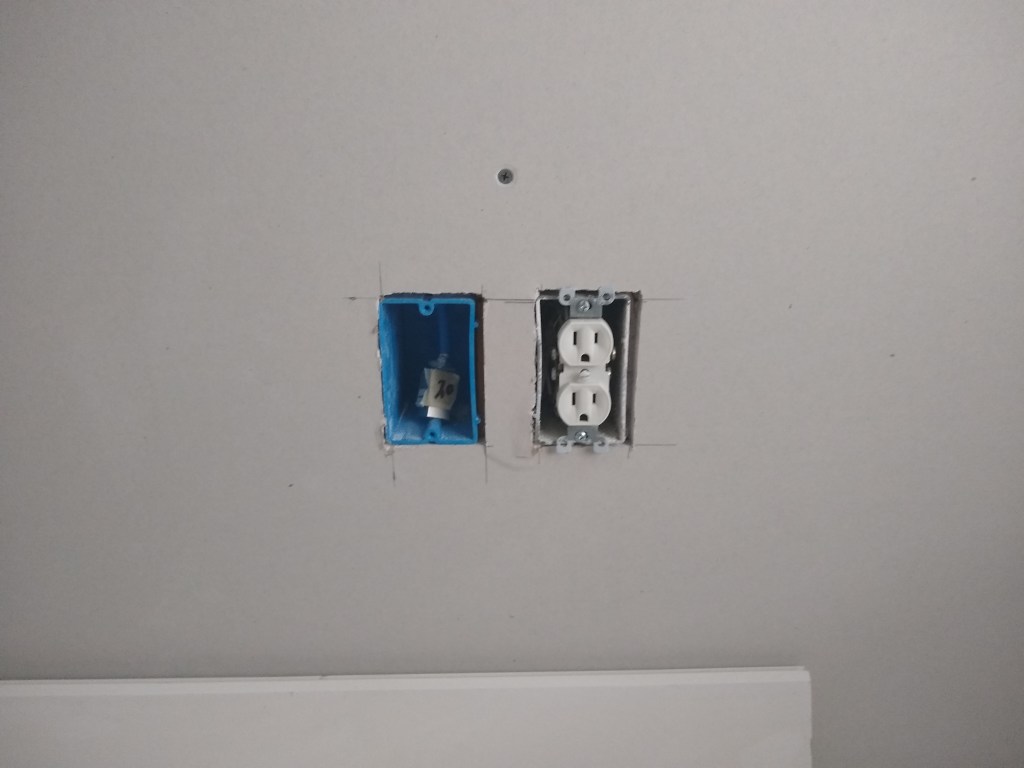
After that, I sorted out the services on the interior wall.

Interior Wall Services

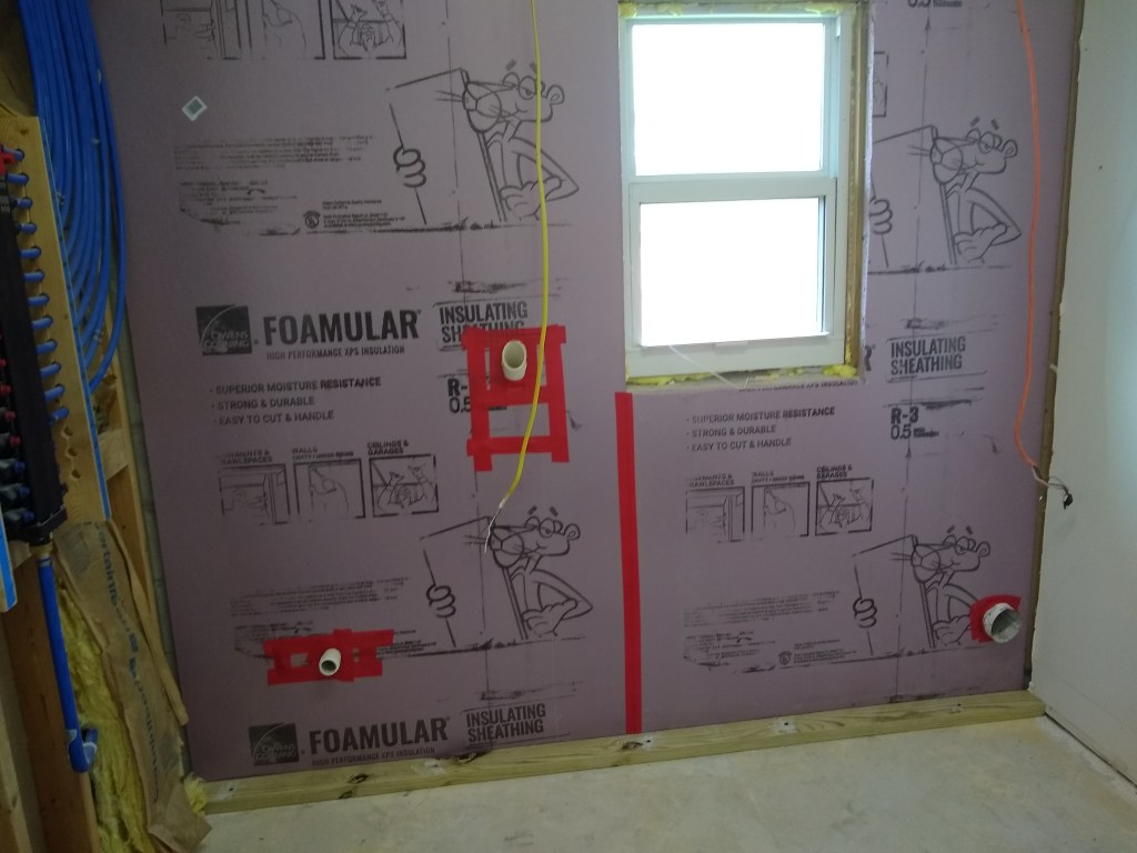
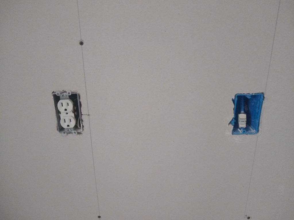
This short span of wall was retained as a place to mount switches (both great room and kitchen) and a place to route the water and electrical lines to the island. In the original plan, I had a 4-gang box: one for a light above the old island location, a second for the can lights in the ceiling, a third for the under counter lights, and a fourth for the kick plate lights. In the new plan, there is no need for separate island lighting. Consequently, the 4-gang box is replaced with a 3-gang box. Beside it is a blue 1-gang box that will house the only Ethernet connection within the kitchen. Below the 3-gang box is another 1-gang box for the GFI outlet (12/2 wire – yellow). This outlet was originally at counter top height, so the wire was not quite long enough to reach to where you would normally put an outlet box (about a foot above the floor), so I raised it up a bit to make it work. I don’t think it looks too odd. That box will also be where I splice in the GFI wire that will be routed under the slab to the island.

The blue and red water lines will also be routed under the slab to the island, along with a separate yellow wire for the dishwasher (separate circuit) and a white wire (14/2) from the 3-gang box to supply power to the kick plate lights there.

After finishing this work, I returned my attention to the master bathroom, where I began framing the toilet alcove (jump back to Master Bathroom – April 2023 to continue the story).

I have ordered a concrete saw in order to cut the new trench that will connect to the existing one. I considered renting a saw or hiring this work out, but after exploring the purchase route, I felt the cost was reasonable and would give me more flexibility. Having my own saw will allow me to attack this without a rental clock running and is way cheaper than hiring it out. The saw is not limited to just cutting concrete, so I’ll have use for it in the future. It will show up in the next post. That’s all for this one.

Master Bedroom Drywall Finishing – March 2023

When I returned from a really fun mini-vacation in Mexico, I arranged to have an inspection of the drywall I recently hung in the master bedroom and workshop so I could move forward with those walls. The inspector not only approved them, but could see that I was doing a thorough job, so gave me a drywall final approval, meaning that all the drywall was approved, even though I had not hung all of it. This was really great because it means that I no longer need further inspections when it comes to drywall. Of course, there will be many other inspections to come, but I have a lot of drywall work ahead of me, so it’s nice that I don’t have to bring an inspector in for that part.

After the approval, I got right to prefilling the walls in the master bedroom, which involves adding a quick-set mud to all cracks and seems before taping. This mud has a hardening compound, so it dries very hard. I used a 90 minute quick-set mud, which means you get about 90 minutes to work with it before it becomes too stiff to manage. By prefilling, one hopes to reduce the likelihood of cracks developing down the road. In the interest of speed, the prefill phase is often skipped.

I also used the quick-set mud I had remaining after the prefill to cover the screws. The screws will receive several coats, but the first one will be with the quick-set mud. Subsequent coats will be with whatever mud I am using.

South Wall Prefilled
East Wall Prefilled

The next step was taping the joints, but first a bit of theory. Drywall is manufactured with beveled edges along the long sides of the board. The short sides are not beveled. When two beveled edges meet they create a tapered edge, which provides a place for the mud to go when taping and coating the joint. The mud will fill the recess, bringing it up to the level of the rest of the board. A butt joint is one that is missing this taper. Without the recess, the mud that is applied to the joint will create a small hump (think speed bump). To hide the speed bump, one must apply mud in such a way that extends the speed bump, making it very gradual. It will be there, but hopefully not visible. Because of the need for this extra effort, one strives to minimize the number of butt joints and, when unavoidable, place them in places that are less noticeable.

I put most of my butt joints above and below the windows. This way they are not very long and in places that are unlikely to show. My largest butt joint runs vertically between the door and window on the east wall. I also have a butt joint at the bottom edge of the window on that wall. So on the east wall I have two butt joints: one long and one short. Alternatively, I could have arranged it in a way where I had a butt joint above the door and one above and below the window, resulting in three short butt joints. In retrospect, I think I should have gone for the three short butt joints. I think it would have made finishing easier. I’ll keep that in mind in future.

I started by taping the flat joints, beginning with the butt joints (vertical joints). By doing that, I was able to avoid any “dangling” tape ends. That is, the ends of the tape of the butt joints would subsequently be covered by the tape used to cover the horizontal flat joints. The tape ends of the horizontal flat joints would be covered by either window/door casing or meet another wall, so they would not be dangling either.

After taping the flat joints, I did the inside corners where the walls meet. After that, I did the outside corners, then finally I taped the inside corners where the walls meet the ceiling. After that, the screws were coated again using the all-purpose mud I had remaining in the pan. Here is the result.

North Wall Taped
East Wall Taped
South Wall Taped
West Wall Taped

The next step is to coat the taped joints. I used an all-purpose mud to apply the tape. All-purpose mud is a heavier mud than the mud I use for coating. The all-purpose mud provides better adhesion, but is more difficult to work with and to sand, so once the taping is complete, I switch to the lighter and more friendly topping mud.

Cover coating the taped joints is done to make the joints flat (or appear flat). I’ll be doing two cover coats. The first one is to cover/hide the tape and, in the case of the flat beveled joints, bring the joint to, or near, the level of the rest of the wall (filling in the recess). For the butt joints, the objective is to taper the hump, consequently, butt joints have a wider coat.

For inside and outside edges, I coated only one side, waited for it to dry over night, then coated the other. As a result, it is a two day job. After finishing the first coat I taped around the outlet box openings where I did a poor job routing them out. I’m getting better at using the roto-zip tool to route out the box openings, but it’s still a “fingers crossed” operation. I had a few with significant gaps that required some attention to make them snug to the box. This was done with paper tape and quick-set mud. Here is the result after the first coat.

North Wall First Coat
East Wall First Coat
South Wall First Coat
West Wall First Coat

The second cover coat is used to provide a surface that is ready for paint (or primer). In my case I will be skimming the walls in order to get the best finish I can (level 5 – see https://nuntawob.com/2021/08/01/drywall-level-1-june-july-2021/ for definitions), so the second cover coat is more about flatness and getting the walls to a point where I could paint them. I will also be skimming the ceiling, changing it from knock-down texture to flat, so for the second coat I will not be touching the tape on the ceiling where the walls meet. That will be addressed when I skim the ceiling. Therefore, the second coat is only focused on the walls.

Prior to applying the second cover coat, I quickly and lightly sanded the first coat to remove any significant irregularities that the second coat could not cover. Not a lot of difference to see, but here are images of the walls after the second cover coat.

North Wall Second Coat
East Wall Second Coat
South Wall Second Coat
West Wall Second Coat

Rather than move on to skim coating the walls, I decided to work on the ceiling first. As previously mentioned, I will be skim coating the ceiling, changing it from knockdown texture to smooth. I did this in the guest bedroom and was happy with the result, so I will do it in the master too. I’m switching to the ceiling at this stage because it’s likely that while doing the ceiling, mud will drip onto the walls. I don’t want to be scraping mud off my newly skimmed walls. Once the ceiling is done (but before priming and painting), I will return to the walls and prepare them for skimming.

The first thing I have to do to address the ceiling is to coat it with all-purpose mud. As with the taping, I’ll use this first due to it’s superior adhesive qualities compared to the Plus 3 mud I’ll use to skim over top of it. The ceiling is a tray ceiling, so the perimeter meets the wall at an angle, so I started covering that first.

North East Perimeter Coated
South East Perimeter Coated
North West Perimeter Coated

I did not have enough all-purpose mud after finishing the perimeter to work on the main part of the ceiling, so I finished for the day. After I picked up another bucket of all-purpose mud I got to work on the rest of the ceiling.

North East Corner

Since the perimeter has had time to dry, you can see how much lighter it is compared to the rest of the ceiling.

South East Corner
South West Corner
North West Corner

Here is a close up of the south west corner.

Close up

This image shows a relatively smooth surface compared to the original knockdown surface which, to remind you, looks like this.

Knockdown Texture

The splotchiness you see in the closeup is due to the fact that part of the cover coat is still wet and that the cover coat has not completely concealed all evidence of the knockdown texture. The next coating will be with the lighter mud and should make all the difference.

Before starting the skim coat, a light sanding is required to remove any obvious lines or other types of irregularities. It doesn’t need to be completely smooth, just enough to make the job of slimming a bit easier. I did two skim coats of the ceiling and then did the same on the walls. By skim coating the walls I am creating a surface that is consistent, not a mix of joint compound and bare drywall. If I did not skim coat the bare drywall, which is optional, the texture difference might show through depending on the paint used and the lighting. Here is the result.

South East Corner – Walls and Ceiling Skimmed twice.
South West Corner – Walls and Ceiling Skimmed twice.

As you can see, the walls and ceiling are looking much better. They are now ready for priming and painting. The type of primer I used was “high build”. This type of primer is a bit thicker than the one I used in the guest bedroom and supposed to be better for filling in small scratches and such, so I thought I’d give it a try, even though I was happy with the regular primer (Kilz) I used before. It seemed to work well, but I can’t honestly say it was noticeably better than the Kilz. In the images I present below, the walls have been primed and the ceiling has been primed and also given two coats of paint. Both the primer and paint is white, so I didn’t see much point in showing images of the various coats, so what you see below is the final product, at least until I decide what color to paint the walls. For now, I am done with the walls and ceiling in the master bedroom.

North Wall Primed, Ceiling Primed and Painted
East Wall Primed, Ceiling Primed and Painted
South Wall Primed, Ceiling Primed and Painted
West Wall Primed, Ceiling Primed and Painted
Ceiling Primed and Painted

I also added new outlets and face plates (except for one on the south wall because I was missing a wire nut). The outlets were installed so I could supply power to the master bedroom. I intend to start work on the master bathroom next, so I wanted to have a power source nearby. I’ll not bother adding face plates for the Ethernet and cable connectors until much further down the line.

I’m pretty happy with how this turned out. On to the master bathroom. Lot’s of unknowns to deal with there (I’m frightened Auntie Em, I’m frightened!).

Ceiling Prep, Garage Cabinets, and More Drywall Hanging – January/February 2023

After returning from the holidays, I knew I would still be waiting for a while before I would have anything from Jennifer, so I decided to continue work in the garage as best I could. I was still missing a 24″ pantry cabinet that would be the center cabinet along the back wall of the garage, so I did as much as I could in the meantime. This meant adding baseboard, painting the walls, and installing two cabinets of the five cabinets that will go along that wall.

This was all I could do along the back wall since the next cabinet to go in was the missing 24″ pantry cabinet. Not wanting to be idle, I shifted my attention to a task I was not looking forward to; preparing the kitchen and great room ceilings for painting.

Prepping the ceilings meant filling all cracks with wood filler, sanding, then caulking. This would be a long, slow, and laborious task, and one that would require standing on a scaffold working above my head. However, it is a very important task, as it would mean the difference between a great looking ceiling and something less than that. So I got to it.

First Coffer Prepped
First Coffer Prepped, alternate angle.

I started with the kitchen ceiling and then moved on to the coffered ceiling. I didn’t take any pics of the kitchen ceiling because there wasn’t much to show other than sanding marks and such. You can kind of see it in the background of the images above. These images are the only ones I took of the coffer prep because once you’ve seen one, you’ll have seen them all. I had 17 coffers to prep and the images above are of the first one. It took about four weeks to complete both the kitchen ceiling and the coffered ceiling. It was hard work, but I am pleased with the results. Once the primer goes on, I’ll know if any further action is needed, but I suspect not (only very little if any). I don’t plan on priming/painting the ceiling until all the walls are ready to prime/paint, and that is a long way off.

I finished the ceiling prep work the day before the missing garage cabinet arrived, so I was able to return to the cabinet installation in the garage right away. I finished installing the cabinets along the back wall in a single day, resulting in this:

Back Wall Cabinets

Note that above the base cabinet on the right, I will add open shelving, but not anytime soon. Here is a shot of all the garage cabinets before adding the hardware.

All Cabinets Installed

The next day I added the handles. Doesn’t that look nice!

Handles Added
Handles and Butcher Block Countertop

You’ll also notice that the butcher block counter top is in place along the east wall, but not attached. It is still wrapped in plastic and I won’t remove the plastic and apply finish to it until I have moved in (or am at a stand still – heaven forbid), as it is of low priority. I’m still waiting on the corresponding countertops for the outside base cabinets on the back wall, but, again, no hurry.

With the work in the garage done for now, I was ready to return to work on the inside of the house, but unfortunately and frustratingly, still no construction drawings from the designer. We had settled on the design changes to the kitchen and master bathroom, so she is supposed to produce construction drawings that I will submit to the permitting office to update my permit. Not wanting to wait, I scheduled an inspection of the master bedroom (framing and electrical) so I could push on. The inspection went without incident, so I resumed work in the master. The first job was to add insulation.

Once that was done I started hanging drywall. I started on the south wall.

South Wall

The next day I worked on the west wall, which required I first add a patch to the ceiling where I previously opened it up to feed the Ethernet cable.

West Wall

I used the two remaining 12 foot long sheets along the west wall so that I could limit the butt joints to above and below the window, so less work required when taping.

I continued in a clockwise manner to complete the room.

North Wall
Northeast Corner
East Wall

On the ceiling along the east wall I had to do another patch, again due to adding an Ethernet line.

When the inspectors came to look at the master bedroom, I also had them look at the wall in the workshop that I framed. Recall that I originally hung drywall along the west wall of the workshop only to pull it down when I discovered that the entrance to that room was messed up. So I framed that wall as I did in the master and had the inspectors give me the okay on it too.

West Wall of Workshop Framed

So I insulated and hung drywall along that wall next.

My next step will be to bring the inspectors in again to okay the drywall I just put up so I can begin taping and mudding. My preference was to call them in only after all the drywall was up, but with the poor response time from the designer, I am requesting inspections piecemeal so I can push on with the things I can control.

I will be off to Cancun for a few days to meet up with family and friends to celebrate a significant birthday of a family member, so I will resume work at the beginning of March.

Plumbing Closet and Bits and Pieces – September/October 2022

In my last post I ended by stating I would call in an inspector for the framing. I did that and the inspector showed up, but unfortunately I was not ready for a framing inspection. The inspector informed me that, although I had completed (most) of the framing, it is not ready for inspection until the plumbing and electrical are done because they can impact the framing. So that was good to learn.

I also mentioned at the end of the last post that I had a problem to fix that was of my own creation. In the front bedroom that will become the workshop, the door opening was not right. The right side was wider than the left (as you enter). You can’t hang a door properly with that.

Although in the above shots it’s hard to see the problem, I show them so that you can get some idea of the repair that took place. I pulled down the drywall in order to get a better idea of what was going on.

From what I could tell, the furring strips where the problem. I had not accounted for the extra thickness they added on the other side of the door opening. But rather than adjust for that, I decided I would frame the entire wall as I had done with the master bedroom and the like. That would provide the same benefits and solve the alignment problem too. So that’s what I did.

Wall section Framed

With that issue fixed, I started working on the electrical and plumbing that would affect the framing. This involved adding new wiring and and securing the existing wiring to the new framing. I started by adding ample outlets to the east wall of the garage. These will be GFCI protected and required 12 gauge wire.

For the master bedroom I ran some new wire under the large window so that one of the outlets next to the bed will be controlled by a switch as you enter the bedroom. Another outlet in the master bedroom was already controlled by that switch, but it was in a place that was of no use to me, so I rerouted it.

Also in the master bedroom, I fashioned a couple of supports to secure the conduit for the Ethernet and the PEX pipe for the spigot.

PEX and Conduit Secured
A Closeup

I secured the laundry room outlets for the washer and dryer.

Although not required for the framing inspection, I removed the tiles from the floor of the master shower. I had been watching a lot of YouTube videos about how to create a shower pan, so while I was “in the neighborhood” I decided to take care of that task.

I then moved to the laundry room to hook up the drains for the washer and the utility sink (that will be relocated to the garage) and their respective supply lines.

Washing Machine Box with Drain and Supply Lines in place
Drain and Supply Lines in place for Utility Sink (to go on other side of wall).
Big Picture

With the laundry room plumbing hooked up, I could now start building the closet to enclose it. I started by opening the ceiling some more so that I could install nailers to support the framing that was to come.

After that I attached the bottom plates for the closet. The closet will have a 24″x80″ bi-fold door, so the opening you see below will accommodate that.

Ready for Framing the Closet

Although it is just a small closet, the sloped ceiling made it a bit tricky. I was only able to get two sections put up that afternoon. I was hoping to do it all in one day.

If you look closely at the section next to the garage door, you’ll notice that there is no vertical framing member up against the adjoining wall. This is because I did not have the room for it (the red PEX pipes are in the way. Because of that I will add OSB sheathing along that side to provide extra support for the drywall when it goes up. It will be tight, but there will be a small gap between the drywall and the garage door casing when it’s all done.

The next day I was able to finish the framing.

Plumbing Closet Framed

Here you can see the OSB sheathing I mentioned above. The opening in the ceiling outside the closet will be drywalled. I made sure there was sufficient nailing surface for that. I don’t think I will do anything inside the closet to pretty it up; only add insulation. There are places where I could add drywall, but I don’t think I want to close anything in. I want to be able to get full access to all the plumbing, so I think it will remain raw. I can always change my mind about that later. I also may find that I want a light in the closet some day, so keeping it unfinished makes that easy.

The remaining work related to the plumbing closet involved wiring up the 3-way switch, moving the switch in the garage for the garage light, and patching the opening I left when installing the PEX. Here’s a reminder of that big hole.

And here is the repair.

From the image on the right (above), you can see where I moved the switch for the garage light. In the original position it was a bit of a reach. Because the switch box for the 3-way switch for the laundry room light was occupying that space (nailed to that stud), the original builders used the next closest stud to attach the switch box for the garage light. Since I had to move the 3-way switch to the side of the plumbing closet, that space became available, allowing me to move the garage light switch to the more convenient location.

Above left is the newly hooked up 3-way light switch positioned on the side of the plumbing closet as you enter the laundry room from the garage. In the image on the right I’m showing the wiring behind it. Notice that I had to introduce a junction box to extend the existing wires. Even though the switch was only moved a foot or so from its previous location (just around the corner), there wasn’t enough slack to make up that small distance. Since I had to add extra wire, I decided to move the existing wires to a location within the closet that was less likely to interfere with the red plumbing lines, which is why you see them coming down from above.

I still have more plumbing and electrical work to do before I can re-request a framing inspection, but some of that is dependent on the design I’m waiting for. I’ll be meeting with Jennifer (the designer) this coming week, so I hope to have more information to guide my next set of tasks and the content of the next post.

Framing Continued – September 2022

In the last post I just finished framing the exterior wall of the master bathroom. My next job was to clear out the tools and such from the master bedroom and get to work framing its three exterior walls I imagined the job of clearing out the master would be a big one, but it didn’t take me too long, so I was able to get right to putting up the foam board on the south wall.

South Wall with Foam Board

As you can see, I used some of the many 2x4s to help keep the foam board pressed against the wall as the adhesive takes hold. I also put down the pressure treated 2x4s that attach to the concrete slab with tap-con screws. While doing that I realized that I had to put up the foam board for the adjacent walls in order to get the dimension for the pressure treated boards correct, since they would be butting up against the foam board on those walls too.

The next day I returned to do the actual framing of the south wall.

South Wall Framed

The next day I started on the west wall and managed to get the foam board up and half the wall framed. So I was getting faster.

Foam Board up on West Wall
West Wall Half Framed

Having made good progress the previous day, finishing up the west wall didn’t take long the next day.

West Wall Framed

Although I made quick work of the remainder of the west wall, I could not start on the east wall of the master because I had to install a spigot on the outside of that wall, and for that I was waiting for the delivery of a special drill bit to create a 1-1/2″ hole through the concrete block. Not wanting to end my day early, I turned my attention to the garage wall that will receive cabinets. As usual, it begins by putting up the foam board.

Foam Board up on Garage Wall

You’ll also notice if you look closely, I fed the electrical wire down from the ceiling. This will power the outlets along that wall. The next day, I framed it.

Garage Wall Framed

The day after finishing the garage wall, Jennifer (the interior designer) came to the house. We had a good chat. The next step was for her to send me a proposal of the services they would provide, which should arrive in the next week or so. In the meantime, I would continue with the framing.

While working on the garage wall, the 1-1/2 inch coring bit I ordered arrived. That was nicely timed, as it allowed me to return my attention to the east wall of the master bedroom. I was a bit apprehensive about drilling out the hole for the spigot. I’d never drilled such a bit hole through a concrete block wall. I did a lot of exploring online and it seemed straight forward enough, but there is something unsettling about drilling a big hole in your exterior wall. But it all went very well. I fashioned a little jig out of a piece of 2×4 lumber to prevent the drill bit from wandering as I tried to get the hole started. Below you can see the jig and the long coring bit attached to the drill.

Hole Drilled – Outside View

I kept the jig in place using my foot as I pushed the spinning coring bit into the wall. Once the hold was started, I was able to remove the jig and carry on. While drilling I used a hose to keep the hole wet. The drill bit is a hollow steel tube with diamonds on the end. It was originally painted red, but as you can see, that didn’t last long once drilling started. I would push the drill in for a bit then pull it out and spray some more water in. It went quite well and it didn’t take long before I was through to the other side (about 8″).

Hole Drilled – Inside View

I was happy with the result. It left a nice clean hole. I fed the new spigot through from the outside and it extended just the right amount.

Spigot Installed – Inside View

And here is what it looks like from the outside.

Spigot Installed – Outside View with Cover Open
Spigot Installed – Outside View with Cover Closed

You’ll notice that the old spigot that is attached to the copper piping is still in place. That will just twist off and I will replace it with a cap, which I’ll eventually paint to match the exterior color, so it won’t be too noticeable.

You’ll also notice that the new spigot is kind of different from what you’re used to. it has a separate male attachment that connects to your hose and plugs into the opening revealed when you raise the cover.

How the Aquor “wall hydrant” connects.
Connected

When looking for a spigot to buy, I came across this and was impressed. It prevents anyone from making use of your water unless they have the appropriate attachment. I will add another one to the west wall, but will not replace the one on the east wall because it is attached to the main supply line, before the supply line feeds into the PEX manifold. So I’d have to take extra steps to take it out of the loop. For now, I don’t plan to do that, but I may change my mind once I’m moved it and fancy another project.

With the spigot installed, I could now return to framing the east wall of the master. And here is the result.

East Wall Framed

As far as I am aware, that is the bulk of the framing complete. I still have to create the closet in the laundry room for the plumbing, but that will wait until after the drain to the laundry tub (to be located in the garage) is hooked up.

Next, I turned my attention to repairing the framing of the kitchen extension. This was a job I was not looking forward to. The extension wall, although plumb, was not properly done (I didn’t do it). Two of the three vertical studs did not line up with the studs of the existing wall. If left alone, the drywall would have a slight but noticeable bend. So I had a lot of shimming and trimming to do. On one side of the each of the two studs I had to fill in the concave part of the bend, while on the other side I’d have to chip away wood to ease the convex part.

What made this so tricky was that the shimming was not uniform. It tapered along the lengths of each stud. To make this more manageable, I did each stud in sections. The studs are about 10 feet tall, so I created three separate shims to make up that length. Using my table top 4″ jointer, I planed down each shim a bit at a time, then took it to the wall to see how it fit. I did this over and over again until it lined up with the studs to the right of it. Once satisfied, I used wood glue and a lot of clamps to hold it in place.

Shimming a Stud

Here you can see two of the shims clamped in place. The shims are from left over furring strips I had, so they are wider than the 1-1/2 inch ends of the studs, but that was okay. The extra width didn’t do any harm. Below is an image taken after completing the first stud (it’s a bit blurry, but you get the idea).

On the other side of the stud I used a jigsaw to make horizontal cuts to the appropriate depth every quarter inch or so all along the length of the stud. To determine the depth of each cut I used a level to determine how far out the stud projected relative to those of the existing wall, creating a series of marks over the length of the stud. I then “connected the dots”, so to speak, producing a line at which I could aim. Note that this is just rough framing that will be covered with drywall, so it didn’t have to be precise. It just had to be close, so this approach worked fine. I then used a hammer and chisel to chop out the wood between the cuts. I did not get a picture of the result of this because there was not much to see. I suppose I should have taken a picture or two of the process, but it was a lot of work so story telling was not on my mind. So this is how I went about correcting the misaligned framing. Below are images of the end result with clamps removed.

Shimming Complete
Closeup of the Overhead Section

The overhead section did not require a shim over its entire length. It gradually lines up, so the shims you see above taper down to almost nothing. This means it is a bit wider at one end than the other. I don’t think this will be noticeable once the drywall is up and finished. If it is, then I will address it with trim.

At this point I believe I can call for a framing inspection, which I’ll do next week. While waiting on that I have another error to fix. Something I messed up. I’ll report on that in the next post.

A Lot of Waiting – May-September 2022

In the last post I mentioned that I had finally gotten my permit, so I could resume work. The first thing I did was hire out the work to re-cut the slab so that the electrical and refill could be brought up to code. On the morning of May 18th a couple of fellows arrived to cut into the slab in the master bath and kitchen. In preparation for this, I cleared the spaces, took down the walls for the alcove surrounding the toilet in the master bathroom, and used my chalk line to outline where I wanted the cuts made.

I was really glad I outsourced this job because these guys made quick work of it and were done within three hours. Well worth the expense. Here is the result.

The next day I replaced one of the 14/2 wires with 12/2 and enclosed them in a conduit. I later (months later) discovered that even that was not sufficient. But we’ll get to that in another post.

With the newly issued permit, I decided I would look for someone to do the two bathrooms. To this end I met with Georgette at David Waller Interiors to see if they could help. That seemed encouraging and we set up an appointment for May 26th to have Georgette come to the house along with some of the subcontractors they use. The electrical guy had all sorts of negative things to say, telling me that a lot of the wiring had to be changed because once the walls have been opened up, you have to replace the wire (with exactly the same stuff, only newer). He recommended I get an inspector in right away to assess the situation. After he left, one of the other guys, Richard, who was privy to the exchange with the electrician, told me that it was not so dire and that he knew a guy who could manage the entire project and handle the inspection process. Having done so much work already, I was concerned about the inspections and was very receptive to the idea of having someone help me navigate that space. So Richard put me in touch with Marty, who was a general contractor (GC) he had worked with.

Marty showed up on June 6th. I really liked him and we had a good discussion. I sent him my SketchUp model so they could provide me with an estimate. Unfortunately, on June 20th (two weeks later!) Marty told me he did not want to take the job. He was too busy. That was annoying given that he took two weeks before he bailed out; wasting my time. So I called Richard again and he put me in touch with another GC, Joe.

Joe came by on June 23rd and looked over the place. He mentioned while looking around that it was a bigger job than he expected, so I was not optimistic that he would take it on. So he left and was going to get back to me. On June 28th, having not heard from Joe, I contacted him and he told me that he could not take the job. Too busy. It’s funny how I have to chase these people down just to find out they don’t want the job. This has become a common theme in this industry. I find that it is rare that someone will call you when they say they will. I frequently have to chase them. So I called Richard yet again and he put me in touch with Mike.

I met Mike on June 30th at the house. He seemed willing to take the job and we arrange to meet again on July 7th, at which time he would bring someone else along to take a look. We met as scheduled and Mike and Scott showed up. Scott would be the one managing the project, so I walked him through the house, explaining what I was after. It appeared that they were still up for the job, so I gave them the code to the lock box so they could access the place while I was away on vacation for the remainder of July, returning early August. They planned to bring other trades by to get their input and to determine costs.

I had a conversation with Scott and the plumber while I was on vacation. The plumber needed a few more details. So I was happy to know that Scott was bringing people by. When I returned in early August I contacted Scott to find out what the situation was. He still did not have a number for me, but did have a drywaller scheduled to come by the house. So I met the drywaller at the house. Nice guy, and we had a good exchange. A couple of days later Scott told me that the drywall guy wanted to return to the house to take more measurements and that Scott would drop by too. So I met with them on August 11th and we had a chat.

Scott proposed that we do it in stages. The first stage would be to get the place ready to the point where flooring would be next. I liked that idea because it would be progressive and consequently, I could take over should I choose after each stage. Scott figured he’d have a price for me on the Monday (August 15th). So I was feeling pretty good about that.

On Thursday, August 18th, having not heard anything from Scott, I texted him asking what was going on. I got no reply that day, but did the next day. Scott informed me that he was still waiting to get with Mike to discuss it. Mike was out of town on some personal business.

The next week I was notified by my apartment complex administrator that my lease renewal was upcoming and asking me about my intentions. To answer that and tell them how long I intended to keep the apartment, I needed to know if I was going to hire Scott and company, and that required I have a cost estimate and some idea of how long it would take. So I texted Scott again on the Monday (August 29th). He responded that he was busy on a job but that he would contact me later in the day, which he did not. So the next day I asked again. I got no response that day (like pulling teeth). He did respond the next day, August 31st, giving me a price estimate of $70k. To that I immediately responded that I wanted a breakdown of the costs. I wanted to know where that number came from. It seemed very high for just the first stage. At the time of writing, September 4th, I have yet to hear from Scott.

Given that I seemed to be in a perpetual state of waiting, I decided I had to do something and made an appointment to have an inspector come over and help me understand what I needed to do. I was concerned about doing this on my own, fearing that they would tell me I had to pull all sorts of things down, but I was fed up waiting for people, so I bit the bullet and decided I would open myself up to whatever they had to say. When making the appointment, I explained my situation, which was that I wasn’t looking for a specific type of inspection (i.e., framing, electrical, etc.), that I was looking for guidance more than anything. So they sent two guys over on Friday, September 2nd.

The two inspectors, Chris and Dennis, were very good. They explained a lot to me and made me realize that I didn’t really need a GC to manage this part of the project. There was nothing drastic that needed to be done. Most of the things they pointed out where things I was happy to hear about and can easily incorporate. So I am now thinking I will proceed without the help of Scott and Mike. I’ll pull in the subcontractors myself, as needed. If I do hear back from Scott I will consider what he proposes, but for now I am proceeding as though I am on my own.

As a result of this, I contacted an interior designer. I want to put together a comprehensive plan of what I am doing. So far I have only had a general idea, figuring I would cross the various bridges when I came to them. But if I am going to bring in subcontractors, I’m going to have to have a better idea of what I want them to do. For example, if I bring in a plumber to do the piping to the bathtub, I need to know what bathtub I am getting. Similarly for the vanities in both bathrooms. I’ll also have to know what tiles I want and such. So I’m looking for some help with this and set up an appointment with Jennifer for September 14th.

In the meantime I have started working on the house again, finally! Now that the inspectors have alleviated my concerns, I am ready to resume framing the exterior walls. This includes the laundry room, master bedroom and master bath, and the east garage wall. So I picked up a load of lumber and foam board and got to work on Sunday, September 4th. Here’s what I accomplished:

Framing Started

It’s amazing how good it feels to be finally moving forward again. I wonder if I’ll ever hear from Scott.

The next day, Monday, I finished framing the laundry room and started on the wall in the master bath.

Framing Started in Master Bathroom

On Tuesday (today) I finished the Framing in the Master Bathroom.

Framing Complete

Next I will tackle the master bedroom. That will require that I empty the room, and there is a lot of stuff in it, as you can see. So that will be a bit or work.

I will end here, since this has been long enough. In the next post I will show more of the framing work and hopefully will have something to share about my meeting with the interior designer.

Permitting – March/April/May 2022

As mentioned in the previous post, I decided to apply for the permits I will need rather than involve a general contractor. In this post I will detail what I did and the experience.

On February 24th, I made a trip to the local permitting office. They explained that I needed to fill out two documents. The first one is an owner/builder affidavit where I acknowledge that as the “general contractor”, I agree that any sub-contractors I hire will be licensed and insured. It also spoke to a few other things like my responsibility to any employees I bring on, which will not apply in my case. The second document was the permit application. In it I was to explain the scope of the work along with the estimated costs. I filled that out as best I could, but provided separate documents to provide details. Here is the description of the work I provided:

Accompanying the description, I provided printouts of selected views of the 3D SketchUp model I created. Learning to use SketchUp took some time. Between that and the many trips to the house to gather the measurements needed to make the model accurate (accurate enough to be of value), it took several weeks to complete the model. I submitted the application on March 21st. Although it took a lot of time, I’m glad I made the effort. SketchUp is a very useful tool and one I will use in future when modeling anything I intend to build.

For the model to be truly useful to me, beyond providing pictures for permitting, it needed to be based on relatively accurate measurements. I know the measurements weren’t perfect, but accurate enough that I was able to really play with the rooms to understand what would fit and experiment with different ideas, all without spending a penny nor lifting a tool. It also made it much easier to create an accurate bill of materials before I go shopping. Here are some of the pics I submitted to the permitting office.

Top
Front
West
Back
East

There were more images submitted, some with greater detail, but from what I have shown above, you get the idea.

I submitted these documents on March 21st and then waited. During that time, there was little I could do on the house without a permit, so moved back into the garage some of the things I had stored in the house while the garage floor was being done. I also identified and marked the wire in the attic above the garage that will be used for the new garage outlets. Of course, those were just a couple of small jobs, so I got a bit impatient and decided it was of minimal risk to do a little more demolition. So I pulled off the strapping exterior wall in the laundry room, the master bath, and master bedroom in preparation for framing them.

After hearing nothing after almost three weeks, I sent an email on April 5th inquiring about the status. The next day I was told the application was rejected because the application form I filled out had a page that was for a different city. That is, the form that they handed me and highlighted was, presumably, the wrong one. So, there are two issues with this. The first was that I filled in the documents they provided. Secondly, they never contacted me to let me know there was a problem. So I went to the permitting office the next day (April 7th) to address it. I spoke with the fellow to whom I handed my application (40+ pages) almost three weeks prior. He remembered the house, but could not, at first, find the documents. That was very disconcerting given that it cost me quite a bit to get so many color printouts. Eventually he found them (whew!) and discovered that the problem with the application was not as described to me in the email. It was simply that I did not provide an estimated cost for the electrical and plumbing work. I updated that then handed it back.

On April 18th, I got a response from the permitting office that I needed to provide an electrical plan and details about the slab cutting and subsequent re-filling. So I got onto Google to find out what an electrical plan was. The electrical plan is a 2D floor plan that identifies how the house is to be wired. So my first thought was that I would update my 3D SketchUp model to add that information. Although it can be done using a SketchUp extension, what was required to make that happen would be overkill. So I looked for another software solution and chose a product called EdrawMax. It required a $69 six month subscription, but was better tailored to the task, so I signed up.

So yet another software tool I had to learn, but it was pretty good and gave me what I wanted. I completed the electrical plan April 28th, so about a week’s work once the tool was chosen and installed. Here is what I submitted.

The above image just shows the electrical plan for the kitchen and bath rooms. That is all they requested. But I decided, since I was at it, to create a plan for the entire house, which would be useful for me. It’s a bit busy, but here is the full plan.

With this I am able to identify what devices each breaker covers, so I’ll be happy to have this on file.

As mentioned above, I was asked to submit a cross-section of what will be done when filling in the parts of the concrete slab I cut out. This is what I created.

Both the cross-section and electrical plan for the kitchen and baths were submitted on May 2nd.

I got a response on May 5th expressing concern about the access to the toilet in the master bath and asking for information on the French doors to the lanai. I discovered that I made a mistake when transferring the measurement from the 3D SketchUp model to the 2D floor plan, which made the entry to the toilet alcove seem narrower than it should be. A good catch on their part. So I corrected that. Note that what I show above is the corrected floor plan. In the original I had it about a foot too long. As for the French doors, I informed them that I was not looking to permit that, as it was done professionally last year and the installers took care of the permitting. I sent my response on May 8th.

On May 12th, I got an email informing me that the permit had been approved. Woohoo! On May 13th I picked up the permit and displayed it in the front window of the house.

While waiting for the permit, I decided I would look for someone to cut (re-cut) the slab. I have to open that up again and make changes so it passes inspection. In the original effort, no soil treatment was done, nor was any vapor barrier added. Also, the wires I ran to the island needed to be enclosed in a conduit and one of them needed to be a larger gauge (12/2 instead of 14/2). So these mistakes necessitated a redo. Not only that, but an inspection will be needed before the holes are filled in. The one thing I was not keen on redoing myself was cutting into the slab and having to break up and dispose of large chunks of concrete. So after picking up the permit I scheduled a crew to come in and do that next week. So it looks like I am finally back in business.

Delays and Garage – January/February 2022

At the end of the last post I mentioned that I would be meeting with an electrician to discuss adding a 240 volt line for the cook-top. That meeting changed a lot. We had a really good chat and he was kind enough to educate me about permitting. He walked through the house and pointed out a number of things that I should be aware of, but most importantly made me realize that I really needed to get permits for the work I have been doing. Many people proceed with interior remodels without permits, but they really shouldn’t. In my case, the changes were so significant that I really needed to follow the process and have proper inspections done. Even though I have no plans to sell the house, one never knows if that will change. If I do decide to sell, the massive renovations that were performed without permits/inspections could cause problems.

This may seem rather obvious, but I was following Chris’ lead on this and he did not want to go down that road. After my discussion with the electrician, I understood that I was skirting the system, and I was not comfortable with that. I decided it was time to set it straight. So I started looking into what was required to get permits. I called the permitting office and they filled me in. I could sign an owner/builder affidavit that allowed me to be my own general contractor (GC), with the understanding that I was responsible for hiring fully licensed and insured contractors. For work I would do, I had to apply for permits myself. The idea of having to wade through the bureaucracy was not appealing, so I started to entertain bringing in a general contractor to manage it and even hand off some of the work. Although this would cost considerably more, the benefit would be that the work would get done sooner and I should be able to move in before the end of the year, thus avoiding the need to renew my apartment lease.

I contacted three different GCs. One fellow, we’ll call him GC1, was busy but would call me the following week to discuss further. I made appointments to meet the other two. The first fellow I was to meet, GC2, was late. I eventually texted him and he somehow lost my information. My text was what allowed him to find it (?). So he eventually showed up and we did a walk through. As we spoke, I got the impression I only had half his attention as he seemed more interested in his phone. Although he claimed his firm could do everything I wanted, I told him I had other GCs to speak with before I made a decision. As you might guessed, I did not choose him. He did not make a good first impression. The next fellow, GC3, did make a good impression. I liked him and was happy with everything he said. The next step was to bring his engineer in to get drawings together and discuss the plan. I still intended to do as much of the work as possible, but we would figure out who would do what. I told him I would get back to him, as I still had one fellow (GC1) to hear from. GC1 never got back to me, so I let GC3 know that I wanted to work with him. We made an appointment to meet again, and he would bring the engineer with him. To make a long story short, the engineer canceled three separate times. GC3 was embarrassed and was genuinely apologetic. He was going to find another engineer and get back to me. More than a month later, I have still not heard from him. I’ve been abandoned.

Around here, this industry has a reputation for not being reliable. It’s sad, but I’ve heard so many stories about this. So I decided to look further into what it would take to apply for the permits myself. This would require creating construction documents or something deemed acceptable. So I would have to learn a software drawing tool that would allow me to produce such documents. I started learning SketchUp. I’ll get back to that later.

In the meantime, I wanted to do something in the house, so I turned my attention to the garage floor. I expected to do that near the end of the renovation, but since it did not require permitting, I decided to move forward with it. I decided to hire someone to do the work so that I could continue learning SketchUp. I was really happy about that decision because I was delighted with the result.

I moved all the stuff from the garage into the house in preparation for the guys who would be doing the job. I chose an epoxy covering with “full flake”. This would seal, protect, and provide a non-slip surface.

The process began by grinding down the concrete surface and filling any cracks.

Next they applied the base coat, starting with the perimeter then filling in the middle.

Once the base coat was down, it was time to apply the flakes.

Lots of Flakes

They started by distributing the flakes around the perimeter then worked on the middle, from the back to the front of the garage.

After fully distributing the flakes, this is what it looked like.

Flakes Applied

That was left for about an hour before they started on the clear coat.

Here it is after the clear coat was finished. I love it!

Clear Coat Applied

And here is another from inside the house. You can get a better sense of the gloss from the clear coat as it dries.

Clear Coat Still Wet

I left the garage door open a bit until the next morning. I could walk on it later that night, but did not. I decided not to walk on it until it was safe to drive on it, which would be three days. I’m happy to report that this job exceeded my expectations. I’m so glad I hired someone to do this.

This job only took about three hours to complete. I was amazed. My neighbor came by and ended up having them do the exact same thing (color and all) to his garage floor. It did take a couple of weeks before they were able to do the job, one of those weeks due to bad weather. During that time I was busy learning Sketchup, starting by modelling the way I wanted the garage to look. Here is what I came up with.

Front Facing
Looking to the Right

In the image above there are a couple of wall cabinets sitting where the A/C air handler sits (not modeled). I don’t have a spot for them, so I just put them there for now.

Looking to the Left

Before putting the other house on the market, I was going to replace the kitchen cabinets to entice buyers. So I purchase the cabinets at the end of 2019. Almost two years later when I finally put the house on the marked, housing prices took off, so my agent felt there was no need to replace the cabinets. As a result I decided I would use them in the garage of this house, which is what you see above.

These cabinets required assembly, so after the floor was done and drying, I used the time to assemble the cabinets and move them into the garage for the time being. The first one always takes the most time because I’m figuring it out. I started with the 24″ base cabinet (B24), shown below. Notice all the other cabinets in boxes in the background.

My First One. B24.

The next day I assembled the 15″ and 18″ base cabinets (B15 and B18). So getting faster.

Once B15 and B18 were done, I moved them into the garage into the position I will eventually attach them.

The next day I assembled four cabinets: two 30″ base cabinets (B30), the sink base cabinet (SB33), and my first wall cabinet (W30). I moved these into the garage and placed them along the wall opposite to where they will go because I will need them out of the way so I can frame the wall upon which they will be attached.

The following day I assembled W15, W24, W30, and the first 18″ pantry cabinet (P18).

I was missing the 24″ pantry cabinet, which is supposedly on its way, so I only had the second P18 left to assemble. I did that the next day. The missing 24″ cabinet (P24) will fill the opening between the two P18s.

There was a lot of cleanup to do after that, which I got to promptly. Now I am in a holding pattern, with respect to work inside the house, until I get permits. I’m busy modeling the house with SketchUp, which will require a lot more work as I add detail. In the meantime, here is a sneak preview.

Floor Plan

The above image is of the overall floor plan. The garage details shown earlier are not part of this model. I will keep that separate. Below is detail of the plumbing (see past post for the actual work). I intend to capture this sort of detail for all the changes I have made and will make. This will take some time, so I will pick away at it until I have modeled everything I feel is needed by the permit office. Even then, I’m sure they will ask for more. It will be a learning process.

Plumbing in Laundry Room

I’m not sure when I’ll be able to resume work on the house. My priority now is to continue modeling and get my permit applications in. How long it takes to get approval is a big question. It will probably involve some back and forth. Hopefully the next post will shed more light on this process.

Drywall, Ceiling – August 2021

In this post I describe the work I did on the ceiling of the guest bedroom.

All ceilings in the house were knockdown textured, which looks like this:

Knockdown Texture

Since the guest bedroom ceiling required a repair (shown in previous posts) I was faced with how to make the patch match the existing ceiling texture. I decided that rather than attempt that, I would skim coat the entire ceiling (existing knockdown) and re-texture it. By doing this I wouldn’t have any issues with matching, and I might even be able to avoid texturing altogether if the skim coated resulted in a really nice smooth ceiling. So that was what I did.

Because I would be skimming over a painted surface, I needed to use an all-purpose premixed mud rather than the lighter variety I had been using for the walls. The all-purpose mud contains some adhesive elements that make it bond better to painted surfaces. The skimming process will require two passes. For the first pass, I used the mud straight out of the bucket.

The guest bedroom (all bedrooms) have a tray ceiling, so after removing the light, A/C grill, and smoke detector (I wrapped the bit hanging down in a plastic bag) I began by skimming the angled perimeter first.

I was pretty pleased with the result. It seemed to smooth out the texture easily. I wasn’t expecting it to look so smooth right away. I finished the first coat the next day. The images below were captured while most of the mud was still wet, so it looks kind of splotchy, but it is pretty smooth.

First Skim Coat Complete

The next day, when the first skim coat was dry, I got up close to scrape and sand the really rough bits (no need for a full sanding). There were definitely some rough areas that were not obvious when viewed from a distance. I did not attempt to smooth them out completely. I only cleaned them up a bit in preparation for the second skim coat, which I expected would cover or fill them in. I decided to use the Plus 3 mud for the second, and hopefully final, skim coat. I was already familiar with it since I used it on the walls, and it would be much easier to sand than the thicker all-purpose mud.

I watered down the Plus 3 mud to a thick yogurt consistency and applied it to the angled areas first, just like the first coat. Being the finish coat, I did my best to limit the lines between pulls of the 14″ knife, keeping pressure mostly on the leading edge. This worked well for the flat areas. The corners of the tray were a different matter since I could not get any of my knives to smooth them out. So I resorted to a sponge. I put enough mud over the area, then used a wet sponge to smooth them out. I left a little bit mud in those corners to sand to get the result I wanted. Here are some pics of the second skim coat before I left for the evening.

Second Skim Coat Complete

The next time up, I sanded the ceiling and touched up a few places. After that, the room was ready for primer (ceiling and walls). I picked up a gallon of KILZ original primer and applied it to all inside corners of the walls and ceiling before applying it to the ceiling. With the primer I had left, I applied it to the west wall. The next day I picked up another gallon of primer to finish the priming of the remaining walls, but also picked up a gallon of ceiling paint. It was my intention to prime all surfaces, but only paint the ceiling, since I knew it would be white. When I figure out what colors I will paint the walls, they will be ready.

After the primer was dry on the ceiling and west wall, I used my 4″ drywall knife and a sanding sponge to scrape and smooth out any obvious lines from the priming. During this process I found some areas on the unprimed walls that were not well sanded. This was missed because it is not easy to see them due to all surfaces being white. So I purchased a hand held light wand to help me direct the light more easily and identify defects. It worked really well and helped me sand out small patches I missed the first time. Following that, I primed the remaining three walls.

The next day, I sanded/scraped what I’d primed and then painted the ceiling with the first coat. That was followed up with the second and final coat the next day. I’m only showing pictures of the final result rather than between coats because there’s not much to see. So here is the final result.

Ceiling after Second Coat (still a bit wet by the door).
Walls Primed, Ceiling Painted

You can see that I was not concerned about the ceiling paint getting onto the walls where they meet. When I eventually paint the walls, I will cut in properly to make a nice edge.

I’m happy with how the ceiling and walls turned out. That I did not have to texture the ceiling was very pleasing. I was hoping I could have a smooth ceiling, and now I do.

With the walls primed and ceiling painted, as far as drywall is concerned this room is done. My objective was to learn all the lessons I could in this room before proceeding any further with the other rooms. So I will resume hanging drywall in the rest of the house.

However, before doing that, I will suspend work on this house for a while and turn my attention to the house where I reside. My primary residence is about an hour and fifteen minute drive from the house I am renovating. I am getting tired of the drive up and back each day. I spend about two and a half hours driving and only around three hours working. My personal circumstances are such that I no longer need to remain where I am, so I intend to sell my primary residence and get a place very close to the reno. That will save a lot of wear and tear on my car and allow me to spend more time working on the reno. To prepare for this I have to do some minor work on my primary residence to have it ready to show. I’m not sure how long this will take, but it will take my attention for the next few weeks. During this time I expect the windows and doors will be replaced, so I will need to drive up for that. So unless that is delayed, I think the next post will be about the that.

Drywall, Level 0 – June 2021

I took an unplanned hiatus through most of May, initially due to a cold. Once recovered from that, I was further delayed by my own hesitation about pulling the trigger on the drywall. I wanted to make sure that was the next step before I made the purchase. After convincing myself that it was, I took the measurements to establish how many sheets I would need, excluding the master bathroom (not sure what I’ll do there yet), My objective was to use as large a sheet as I could where possible to reduce the seems that would subsequently require taping. My measurements revealed that I would need 35 sheets of 12’x4′ and 60 sheets of 8’x4′.

I first visited Lowe’s intent on making a purchase and arranging delivery. Unfortunately, Lowe’s would only deliver the drywall to my garage. I wanted it placed inside the house. I would be hanging it by myself, so moving it from the garage into the work space would be a major chore by myself. So I went to Home Depot next and, fortunately, for an extra charge they would carry it into the house. I didn’t make the purchase that day. Instead I went home and looked online for other options before I committed to it. I didn’t find anything, so I called Home Depot and made the arrangements over the phone. We set a date and a time window .

I drove up to meet the delivery crew on Wednesday, May 19th at the designated time. When the driver arrived he was by himself, which surprised me because moving all the drywall into the house would be a big job for one person. I mentioned this when he approached me only to learn that he was not planning to carry it into the house; only put it in the garage. So, he got on the phone with the store for about half an hour with little result. In the end he left without unloading the drywall. So I drove to the store to discuss it with them. They made arrangements for another attempt on the Monday, May 24th, this time with additional labor. I drove up again on the Friday and waited. I stopped in at the store to make sure all was in order and was told it was. Nearing the end of the delivery window I got a call informing me that they’d have to do something else because the usual delivery service did not carry into the house. So we set it up for the following Friday. The third attempt was successful. My drywall was placed where I asked.

Note that the above pictures were taken after I had already finished hanging the drywall in the guest bedroom, so if you looked really closely, you’ll see that there are less than 35 sheets of the 12′.

The next day I hung my first ever sheet of drywall! I had several reservations about doing this myself, especially with the 12′ sheets. My biggest concern was how I was going to mount a 12′ sheet on the upper section of the wall up to the ceiling. I did some research on YouTube and learned that I could do it using the lift I had. Until viewing that video, I’d only used the lift for raising things up to the ceiling and was unaware that it had features to assist with hanging drywall on high walls. That was my first and biggest problem solved. I would not have to rely on another person. A big relief.

Another concern I had was how I would maneuver the sheets from one room to another. I was pretty sure I could use a couple of dollies I had, and that turned out to be the case. At first I used both dollies. It worked, but was little tricky steering. I then discovered that using one was sufficient and much more maneuverable. So another problem solved. Below I show a big 12′ sheet on the single dolly.

Moving Drywall Sheets

Now that I’ve shown how I move the sheets by myself, let me show the process of hanging a 12′ sheet. Using the dolly, I move the sheet into the room I am working on and get it close to the lift. I then have to physically pick up the sheet and place it onto the lift. That is not easy, but after trying several techniques I figured out how to do it without too much effort.

The pics above are of the sheet on the lift positioned to go on the north wall of what will be the office. I had already finished hanging the guest bedroom and the west wall in the office before I started writing this post. It was only when I started describing the process that I realized that pictures were required. So what you’re seeing is not my first attempt. The pics show the lift moved close to the wall. This is the first step. Next I must tip the top of the sheet so that it rests against the wall. In the image below, you can see that the bottom edge of the sheet is still supported by the lift, but the top edge is not. It is now leaning against the wall. For this to work without the lift rolling away, it has a set of brakes with rubber ends to prevent the lift from moving.

On Lift, Against the Wall

Here is a closeup of the brakes deployed.

Lift Brakes

Now I just raise the sheet into position. It simply rides up against the wall as I turn the handle.

Actually, with a tight fit like this one, it takes a bit of maneuvering. I turn the crank, adjust the sheet, turn the crank, etc. But it is pretty straight forward. Once in position I pull out the ladder and drill a few screws into place at the top. Three screws are enough. Then I can roll the lift away and it will hang by itself.

Sheet tacked and Lift removed.

After that it is just a matter of adding enough screws to firmly fix it in place. Before I place the bottom sheet which, of course, does not require the lift, I cut out the window opening. But I will discuss those details later. Now that I have explained the process of hanging sheets, I will describe what I experienced as I began the process.

Being new to this, I decided it would be a good idea to gain experience (i.e., make beginner mistakes) in a room that would be the least used. So I started in the guest bedroom. I figured out how to move and lift the sheets by myself, as described above, but there were still several other firsts I had to face.

The first sheet I hung was a full 12’x4′ sheet, requiring no cuts. Here it is below.

The next sheet, however, would require cutting to fill the relatively small area adjacent to my first sheet. Cutting a sheet seemed pretty simple, so I just followed the directions I found online. Sure enough, it was simply a matter of cutting a line through the paper with a utility knife, then snapping it. The sheet broke easily on the scored line. I then used the same knife to reach under and cut the paper on the other side. Voila, another mystery solved. It also required one more step; using a rasp to smooth the freshly cut edge, but that was very simple using the following tool.

Drywall Rasp Lifter

This tool has two uses. It can be used to raise the bottom of a sheet of drywall using your foot and a lever action to meet the sheet already in place above it. The idea is to create a tight butt joint. The other use comes from the part in the middle of the tool that is a rasp you can run along the edge of a freshly cut sheet to smooth it out. It works really well.

So I fastened that piece to the end of my first sheet to finish the top of my first wall. The bottom part was a bit more involved, since it required some cuts for outlets, as shown below.

First Wall Hung

To cut the openings for the outlets, I started using the manual approach whereby you simply measure the distances and then cut with a drywall saw.

Drywall Saw

This worked fairly well, but it was very time consuming. It also had the disadvantage of not always lining up how you expect. You measure as best you can, but when you actually fit the sheet, there will inevitably be some variance. Here is what it looks like close up.

These are not bad and will be easily covered by the face places, so no patching will be required. However, the measuring and cutting before putting the sheet up really interrupts ones momentum, so I decided to try my hand at using a cutting tool with a RotoZip bit. Here is what I bought.

Notice that the RotoZip Bit has a smooth tip. This is the part the will guide the bit along a surface without cutting it, as I describe in a moment.

My research revealed that a cutting tool and RotoZip bit seemed to be the preferred method used by professionals. The concern for me was that it was going to take some practice to learn how to use it without making a mess. The way it works, is that you first remove the outlet and push the wired to the back of the box. You make a note of where the center of the box is then place the sheet over the outlet and fasten it loosely using screws that are not really close to the outlet itself. You measure to where you noted the center of the box to be and plunge in with the cutting bit. You then move the bit (i.e., cut) over to the edge of the box. You’ll feel the bit stop when it touches the inside edge of the box. Then you pull the bit out a little and move the bit over to the outside edge of the box and trace around it, cutting away the drywall. This is the tricky part for the inexperienced. You have to get a feel for it, which takes a bit of time. Here are my first three attempts.

As you can see, these are pretty ugly, especially the third one, and will require patching. For a professional, patching mistakes like this is a real nuisance, costing time/money. However, for me, I am not time constrained, so I will “embrace the suck” and view this as part of the process. I did get better and expect I will continue to. Here are my fourth and fifth attempts. They are not perfect, but are acceptable and will require no patching.

Fourth and Fifth RotoZip Attempts

I also use the cutting tool for other openings, like doors and windows. Here is the second wall I started in the guest bedroom. The 12′ sheet covered the doorway, so I used the cutting tool to open it up after the sheet was in place. It works nicely for this and is a much simpler process as one simply follows the door frame (no need to pull out and plunge in). As a side note, the hole in the ceiling was done a long time ago as we explored the framing. It will be patched in due course.

Cutting the Opening for the Door

Here are a few shots of the guest room after I finished hanging the drywall.

During the process of hanging the drywall in the guest bedroom, I found that setting the screws was a bit erratic with the impact driver, even using drywall screw setter bits to limit the likelihood that I would drive the screws too deeply into the drywall. You’re supposed to sink them below the surface without breaking the paper. So I decided to purchase a drywall screw gun; a tool specifically designed for this.

Drywall Screw Gun

With this tool, when you pull the trigger, the motor spins, but the bit does not turn until you press the screw into the drywall. It is the pressure that causes the clutch to engage, and then it drives it in quickly. You can adjust the depth to sink the screw head to your desire depth. I found this was a very worthwhile purchase and made the process much more consistent. I’m very happy with it.

In addition to screws, I am also using construction adhesive to glue the sheets to the studs, where possible. Although many were split on the need for it, it appeared that most felt it was worth while and that it would reduce the likelihood of screw pops in future. The idea is that as the framing naturally moves (slightly) over time, the extra adhesion will prevent the drywall from pushing and pulling against the screws. The extra cost for the adhesive is not much and it takes very little time to apply, so I figured I’d do it. Unfortunately, it can only be done on interior walls, since the furring strips you screw to on the exterior walls are covered with an insulating material, so I’m not getting 100% coverage.

Some other lessons I learned while hanging the drywall in the guest bedroom was that it is a good idea to look for opportunities to do some prep work. Many walls are not straight and will require shimming. Also, in some places, especially in the corners, there is not always a lot of wood available to screw the sheet to, so it can be beneficial to add nailers.

As of the time of this posting, I have hung two bedrooms (guest bedroom and office) and am half way through the third bedroom (workshop). I have ordered 100 feet of mass loaded vinyl to use as sound insulation between the workshop and office, which will arrive this weekend. I will put it up and see how it works before purchasing more for the other interior walls to which I intend to add sound insulation. Where it makes sense, I want to reduce the sound that can travel between rooms (i.e., bathrooms and bedrooms). But I’ll talk about that in another post. Once the drywall in the workshop is hung, I think I will return to the guest bedroom and try my hand at mudding and taping so I can get some experience with that before continuing with the hanging. It is likely that the lessons learned from that experience will impact how I hang the remaining drywall. Since there is so much more drywall to hang, now’s the time to discover them. So stay tuned.