Following the installation of the stainless steel backsplash in the kitchen, the house was in a state where I could move in. Obviously there was still a lot to do, but all the things I needed to function were in place. I would spend most of my time preparing for the move. This meant a ton of sorting and purging, and eventually cleaning in preparation for moving the furniture from my apartment. In this post, I do not intend to cover that part of the process. Instead I will focus on the other things I attended to in between those activities.
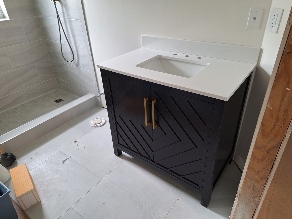
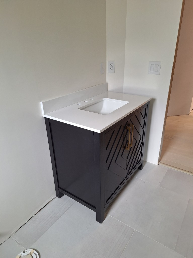
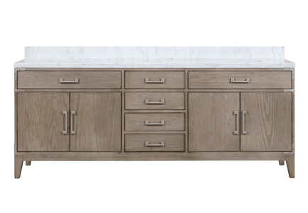
One of the first things I did was to acquire a vanity for the guest bathroom.
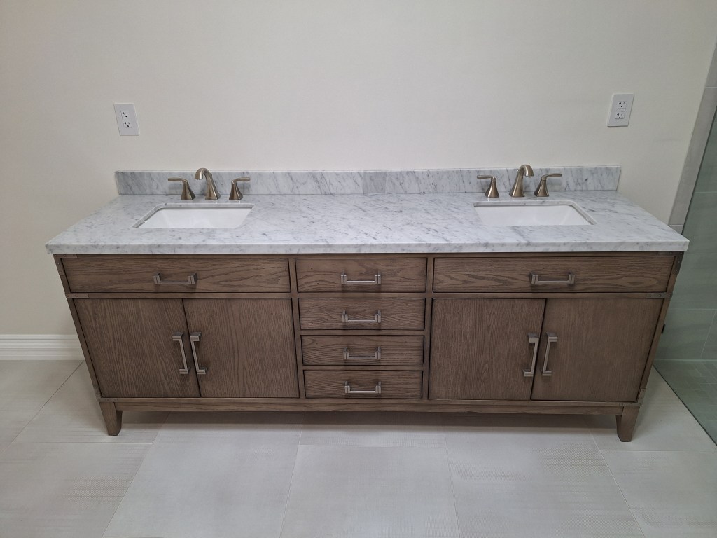
Vanity Set in Place
Vanity Set in Place
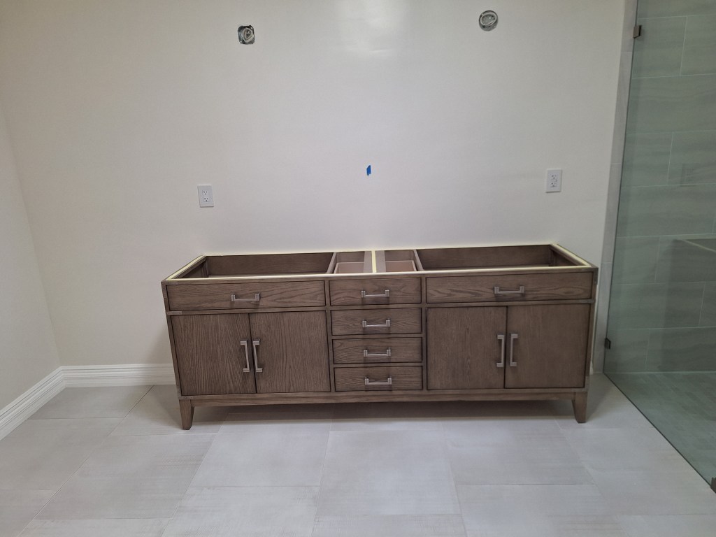
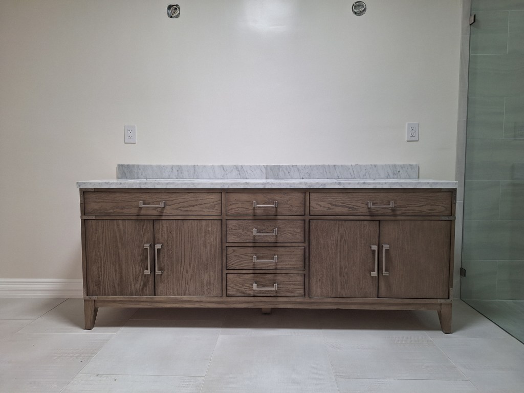
As you can see, I opted for a free standing unit. The vanity you see above is simply placed where I want it. It has not been secured in these pictures because other things in the bathroom need to be installed before I secure it (like the baseboards). I will be replacing the door handles on the vanity to match the other hardware in this room. These handles are what came with the unit.
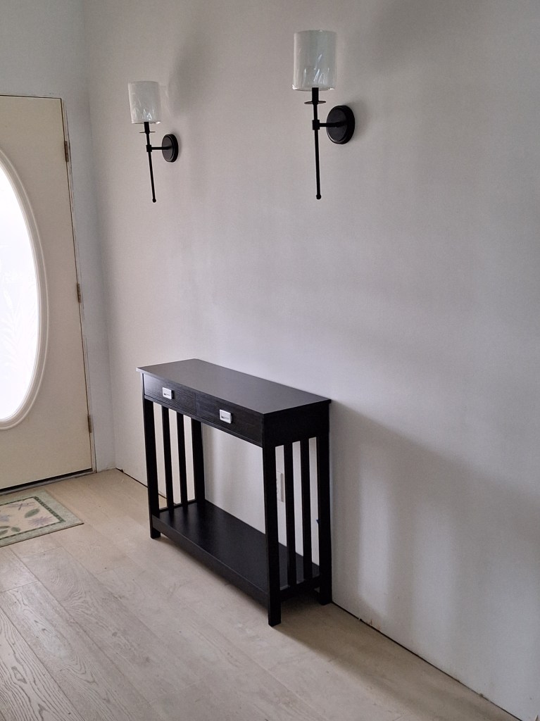
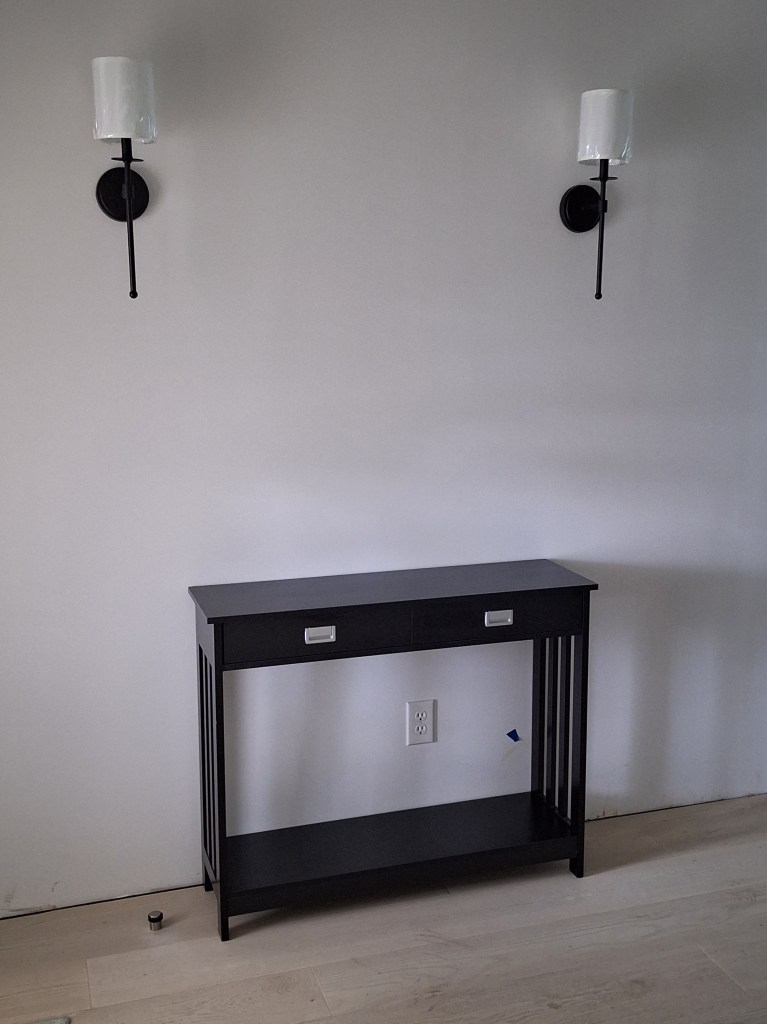
Another thing I attended to was getting a console table for the foyer. I found something online that I thought looked pretty good, so I ordered it and assembled it.
Console Table for Foyer (first attempt)
Console Table for Foyer (first attempt)
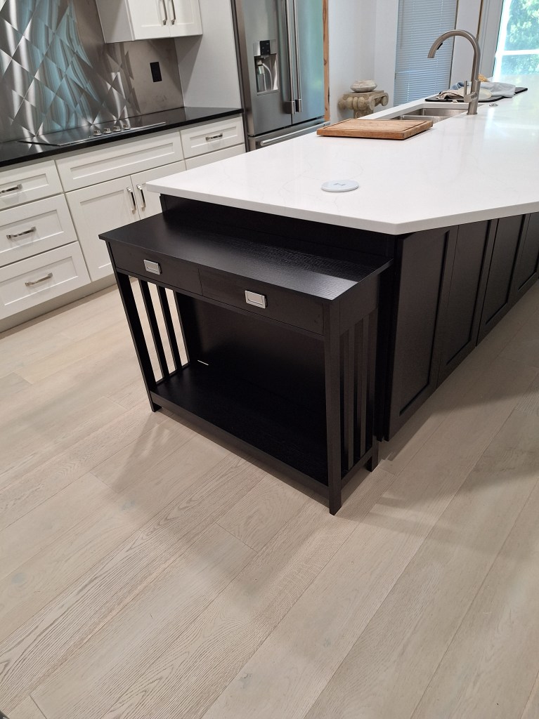
Although I liked the style, I thought it looked a bit small for the space, so decided not to use it there. However, I got the idea that it might work well in the kitchen at the end of the island as you enter from the garage.
Console Table in Kitchen
Console Table in Kitchen – drawer open.
Console Table in Kitchen
I was very pleased with this arrangement. I will be entering the house mainly from the garage, so when I do this will be where my keys will go, along with any other things that one typically places on the counter as you come and go. This provides a very nice landing zone, keeping the counter free.
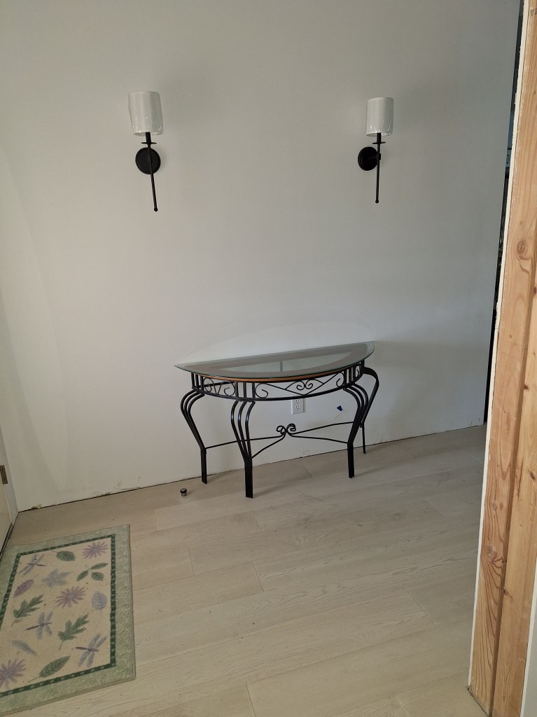
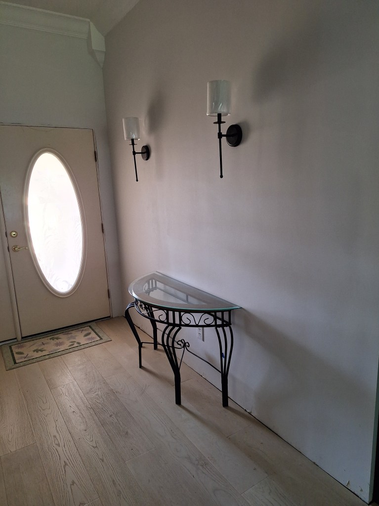
Of course, I still needed something for the foyer. Then it occurred to me that I could use the table I’d previously used as a sofa table. I moved it into position and was immediately pleased with how it looked.
Console Table for Foyer (second attempt)
Console Table for Foyer (second attempt)
This is a bit more substantial and I like the combination of metal, wood, and glass. I added a mirror to complete it.
Foyer Mirror
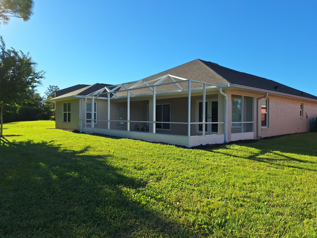
The screening that encloses the lanai out back was in need of replacement. A couple of the screens had been missing for some time, so I decided to attend to that. I chose to outsource this work to make it quick, but I had to prepare for that first, which meant removing the existing screening so that I could wipe down the aluminum cage, which had a lot of mold built up on it from neglect. I also pressure washed the floor, which cleaned it up, but it needs a lot more attention and I have yet to decide what I am going to do there.
Removing the Old Screens
Here is a shot of the lanai after the old screens had been removed.
Original Screens Removed
And here is a shot from the same angle with the new screens in place.
New Screens Installed
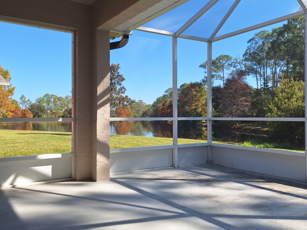
The new screening has smaller openings than the previous screening. This is supposed to keep out the tiniest of bugs (often called “no-see-ums”). It was a bit more expensive, but I thought it was worth it. I want to be able to keep the doors from the house to the lanai open during nice weather and don’t want to have to worry about bugs getting into the house. Another thing I did along this line was to use spray foam to fill voids at the joints in the aluminum framing. Even with the previous screening in tact, the little lizards had a way of getting in. Although they are harmless, I prefer they stay outside. Since doing this, I’ve not seen a single lizard, so I think it has been a success. And what a nice view I have.
View on a Sunny Day
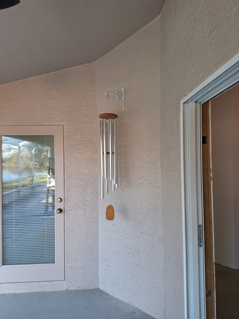
I also put up my wind chimes, which have been sitting patiently collecting dust for years.
Wind Chimes Hung
I like the look of the chimes, but positioned them in a protected location because they can get loud and I don’t want to disturb the neighbors.
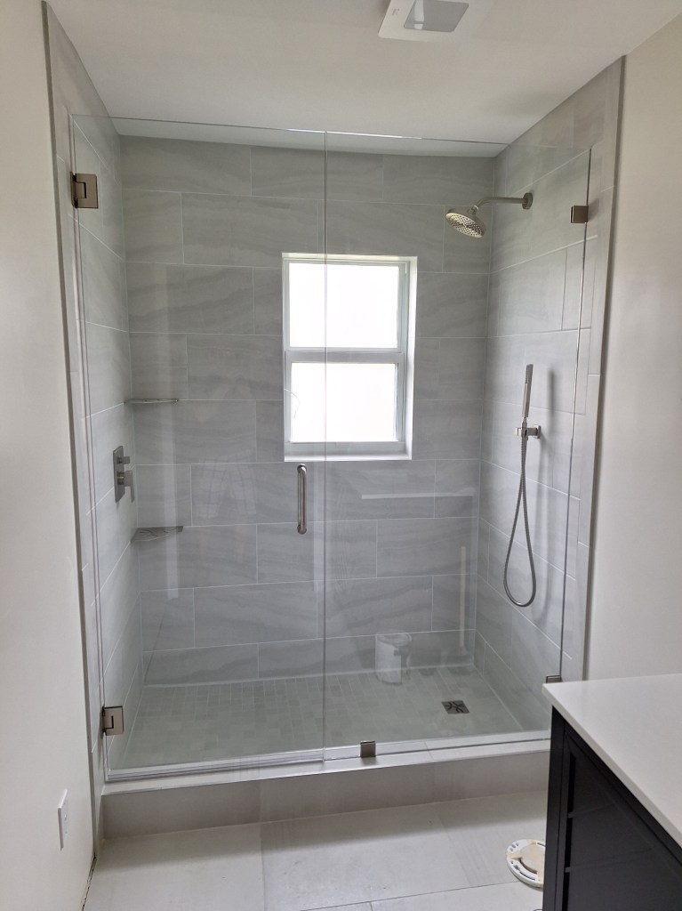
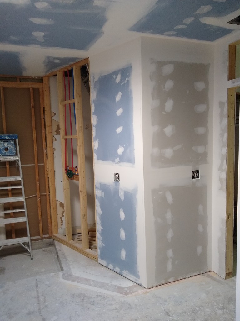
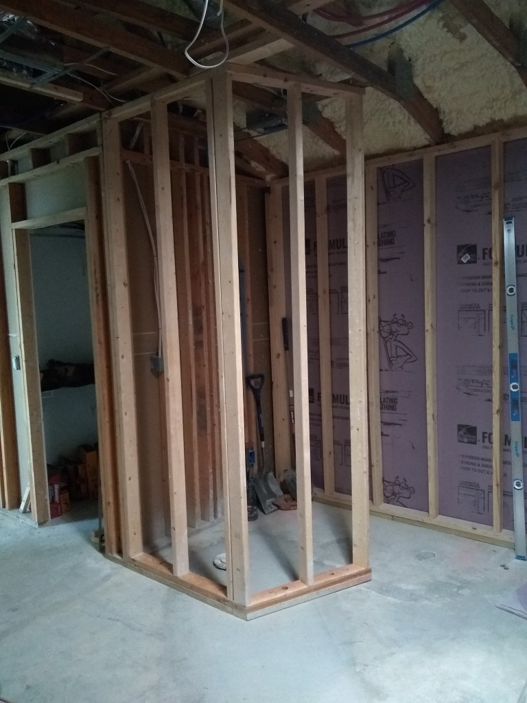
Although the guest bathroom won’t be fully functional until after I get the baseboards down (a prerequisite for the toilet and vanity installation), nothing was stopping me from getting the glass shower enclosure installed. I hired the same people that did the glass wall for the master shower. For this installation, though, I added a door, since the area is much smaller. I was happy with the result.
Glass Shower Enclosure
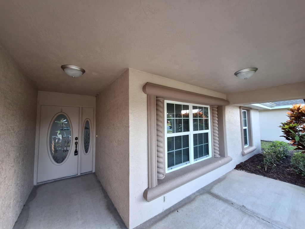
Another chore I attended to just before the movers arrived, was replacing the two overhead lights at the front entry to the house.
New Overhead Lights
These fixtures are pretty simple. The original ones were looking a bit ragged, and I think these clean up the entryway nicely. Like the flooring in the lanai, I’ll do something with the entryway here. The bare concrete is not very nice.
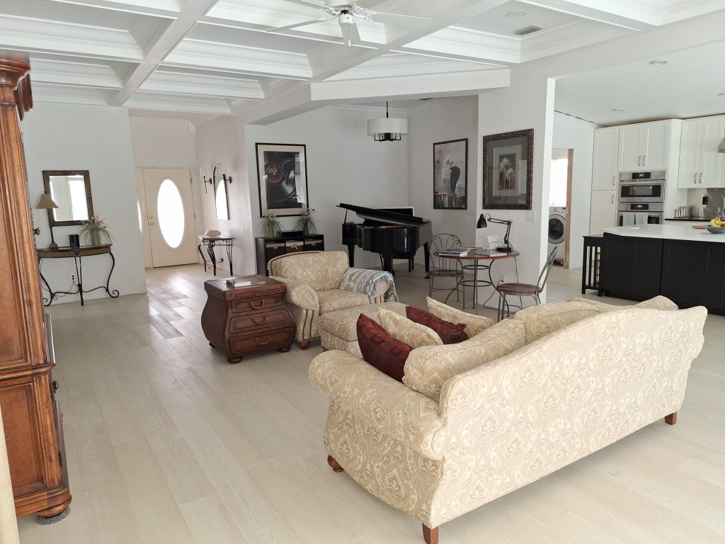
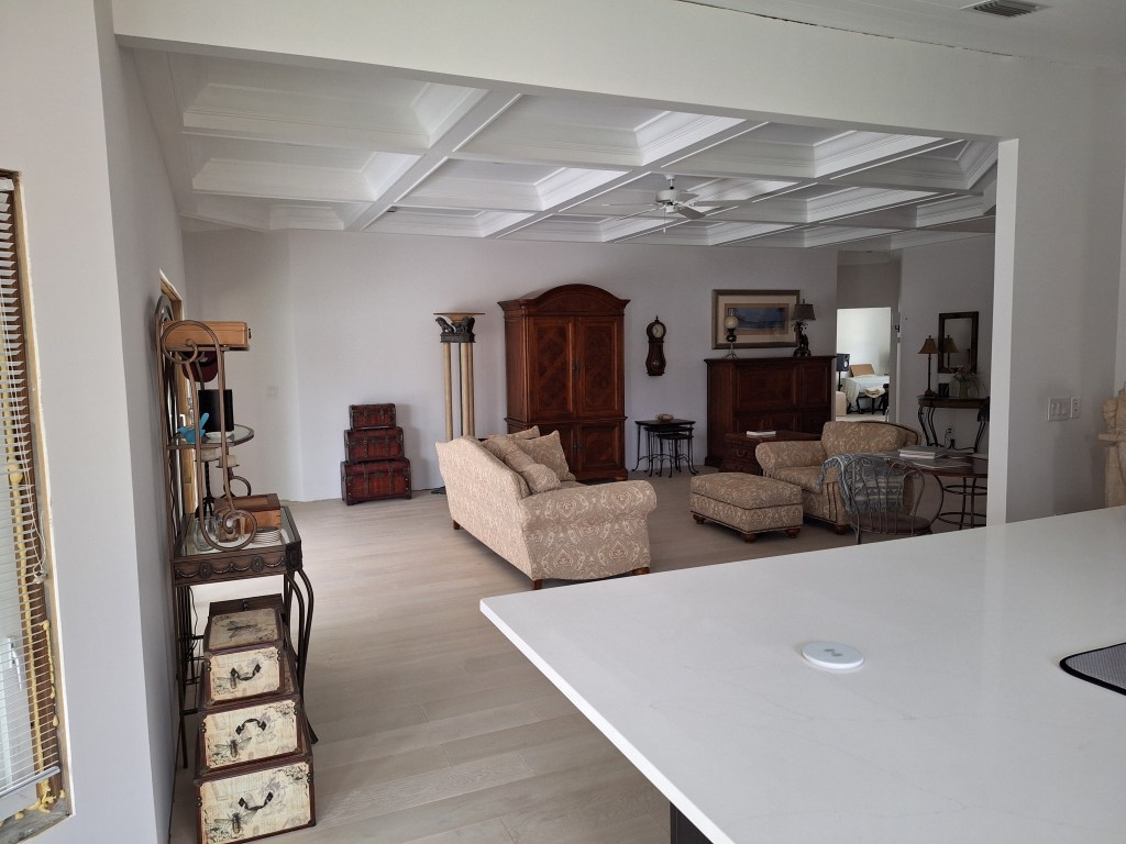
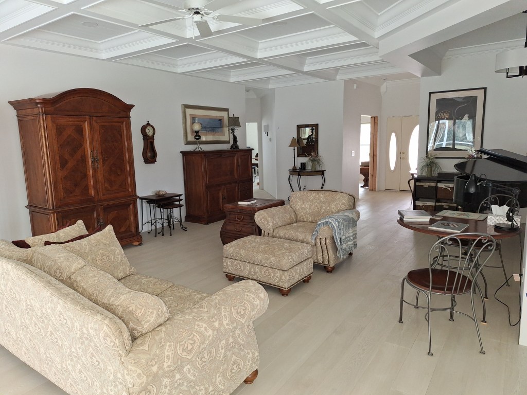
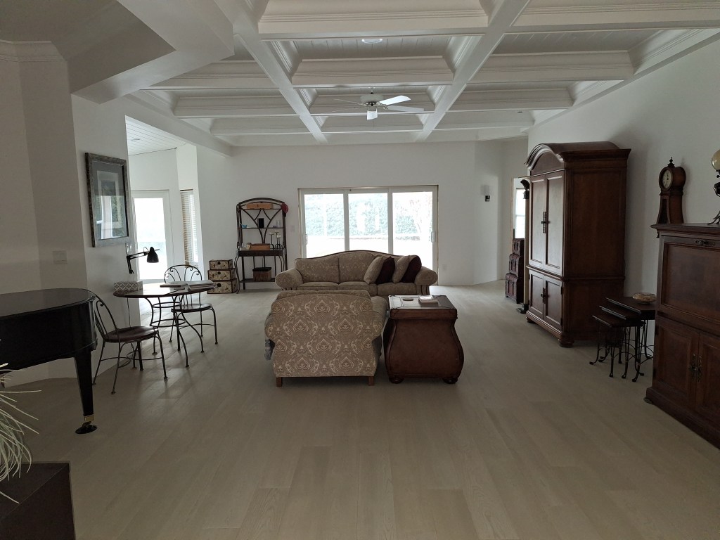
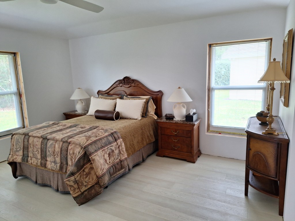
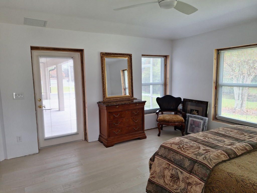
The actual move took place on November 10th. The weather was perfect. The movers were great and made quick work of it, leaving me to arrange things the way I wanted them. This is what I settled on.
From Master Bedroom
From Kitchen
Looking North
From Foyer
I was surprised with how my traditional furniture worked in this room. It was my plan to replace all this and move toward a more modern look, but after setting it up, I was pleasantly surprised with the look. I really like it, so will be keeping my existing furniture. I already intended to keep the bedroom set. I bought it ages ago and have always liked it.
From Entry
Toward Lanai
Toward Great Room
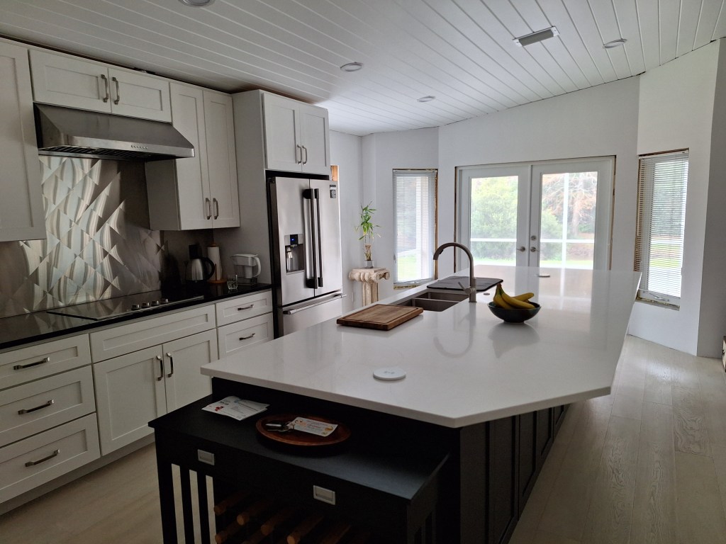
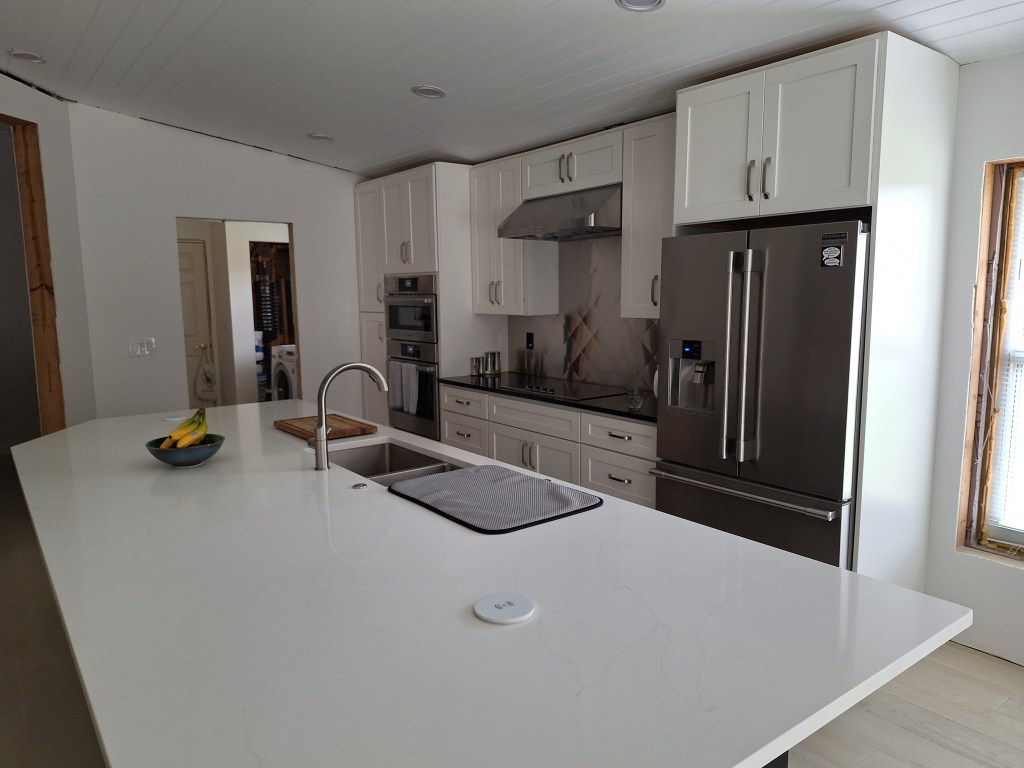
Here’s the kitchen.
Toward Lanai
Toward Laundry Room
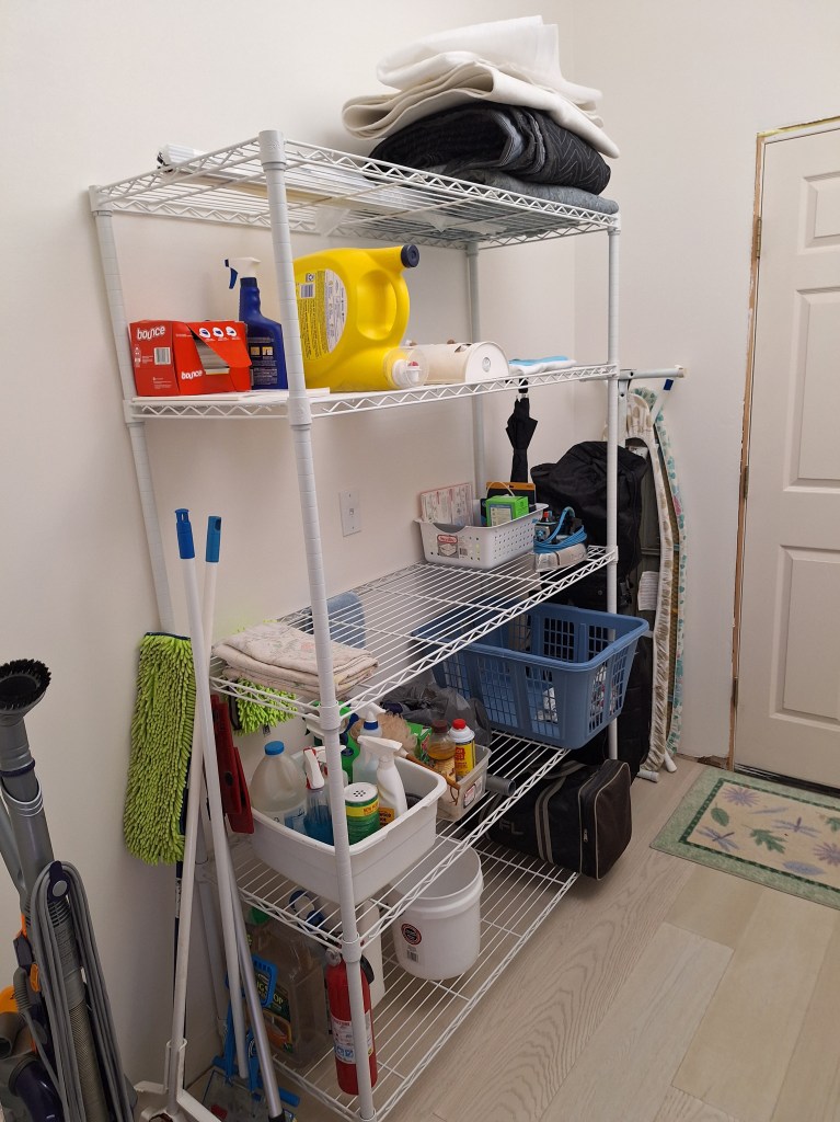
In my previous post, I showed a picture of the temporary rack I put in the laundry room to serve as storage until I built in cabinets and a bench. Here’s a reminder.
Temporary Rack – take 1
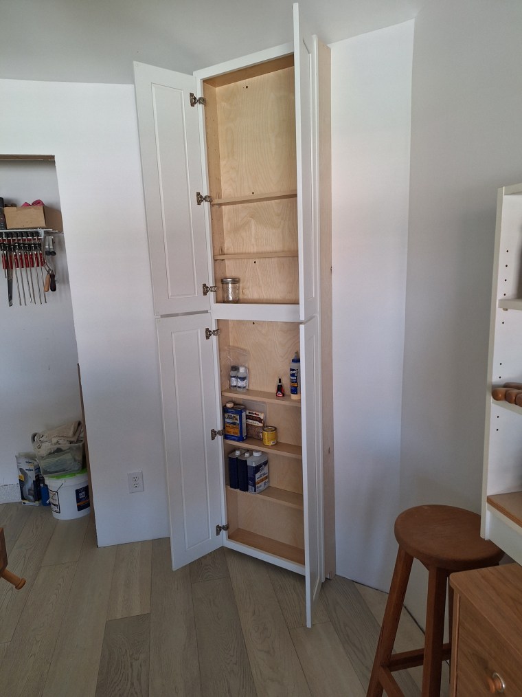
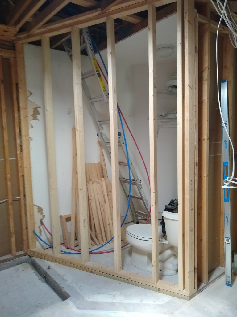
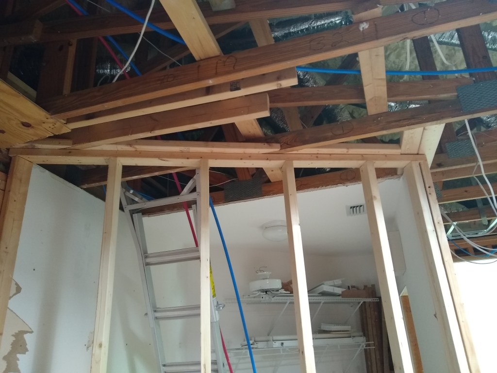
One evening while I was sitting peacefully in the living room, I heard a loud crash. I jumped up to investigate and discovered it was the shelf in the closet of the workshop. It came crashing down. I had been storing a lot of things on that shelf, including many clamps. I don’t have a proper picture of it, either before nor after, but here is one that will give you a small peek of it before it fell.
Peek at Closet Shelf on the Left
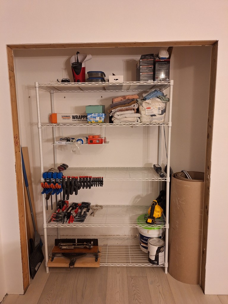
Fortunately, there was no real damage. I noticed a small ding in the flooring, but you had to really look to see it. After this, I decided that rather than put the shelf back up and ensure it was suitably secured, I would move the 5-tier rack from the laundry room into this space. I contemplated doing this when I first got the rack, thinking it would fit nicely here until I properly built out the closet, but decided it wasn’t needed. Ironic, eh?
5-tier Metal Rack Moved to Workshop Closet
As you can see, I have plenty of extra storage space available, so that is a nice benefit. The rack in the laundry room was replaced with a slightly smaller one since I didn’t really need all the space the larger rack provided. This one is made of plastic rather than metal, which is fine since it would not be supporting anything very heavy. Here it is loaded up with what I had before.
New Rack for Laundry Room
I am now living comfortably in my new home and am really happy about that. It’s really pleasant, which is aided by the beautiful weather we’ve had since I moved in, allowing me to keep the slider in the living room open most of the day.
There is still a lot to do. None of the trim work is done. There are no interior doors, and the crown molding in the kitchen has yet to be done. I’m contemplating hiring out some of that work, but will decide on that later. With the holidays approaching, I’ll be doing quite of bit of traveling, so until the New Year I am just going to enjoy my new home and take it easy. I’ll get back to work next year.
To end this post I’ll leave you with a picture I took the morning of November 25th from the lanai. I don’t usually get up so early, but that day I woke up as the sun was about to make an appearance, so I captured it.
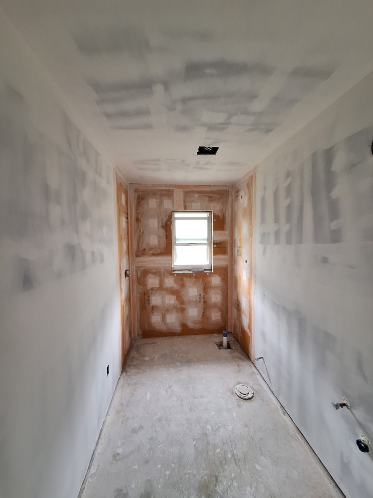
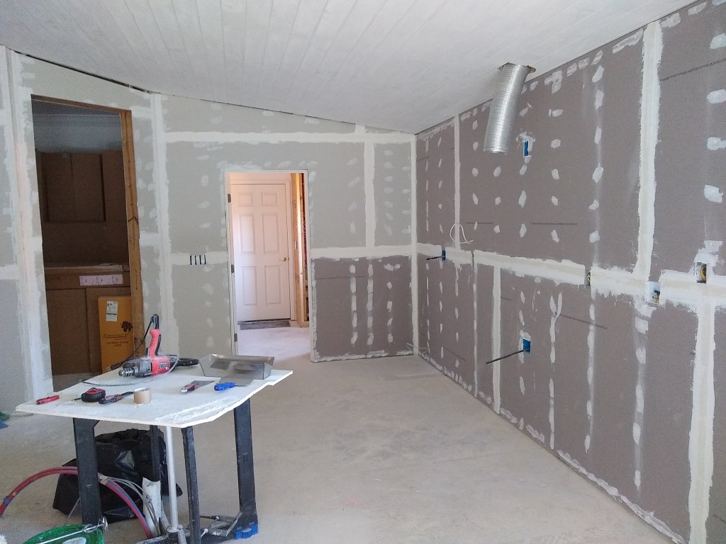
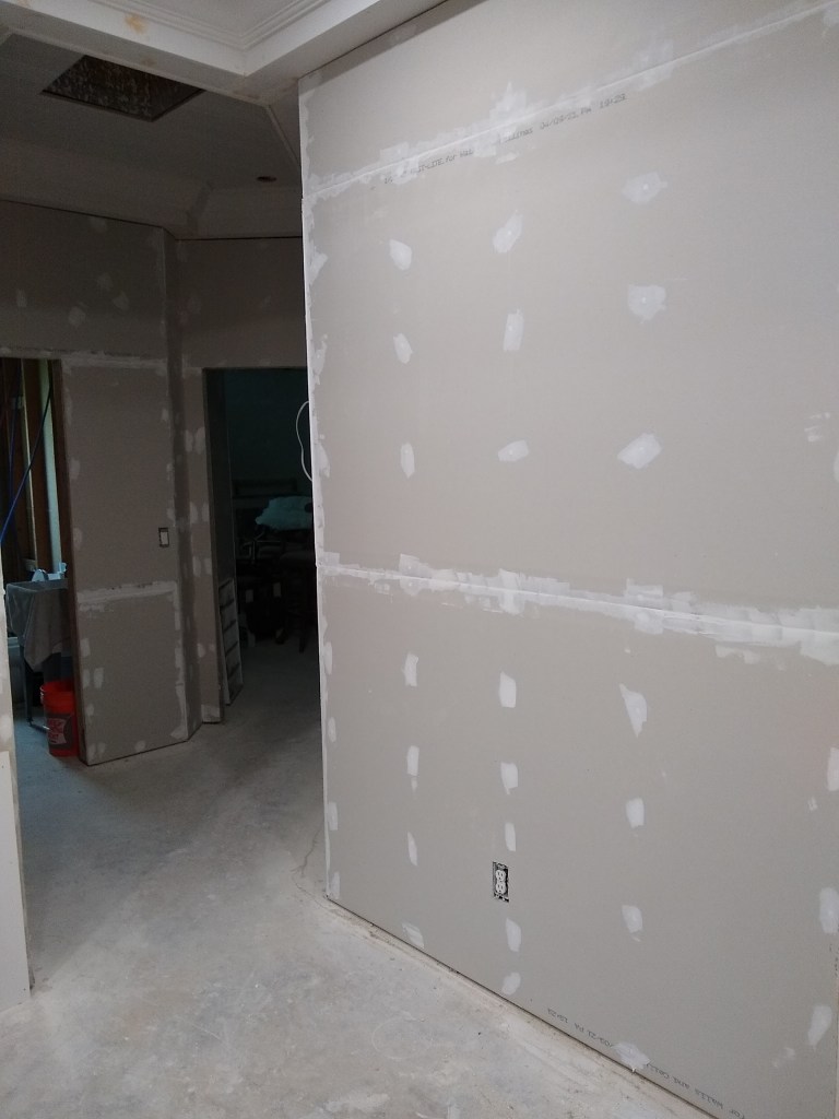
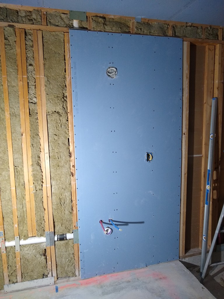
The last post finished with me having just finished taping the drywall in the guest bathroom. So we start this post with the various coatings of that taping job.
First Cover Coat of Tape
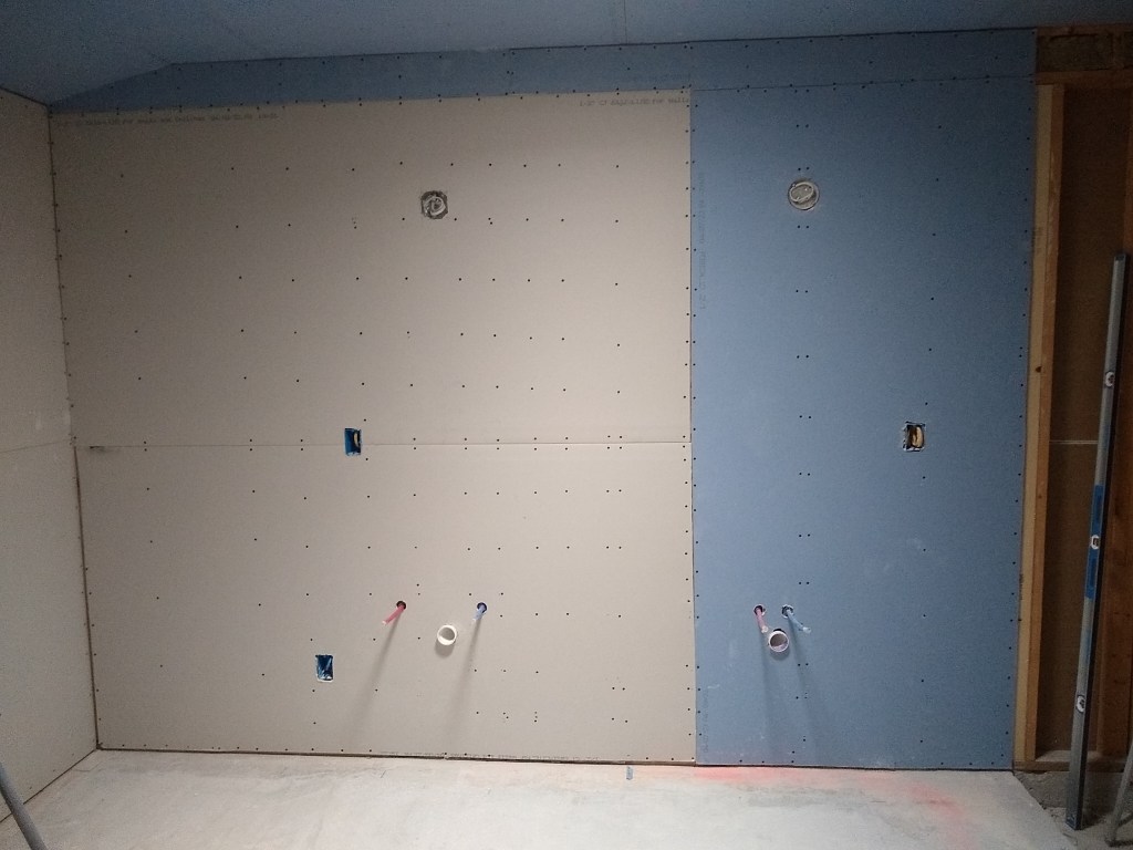
After the first cover coat of the tape, we apply a second to widen the coverage in order to flatten the seams. In between each coating, sanding is done to prepare for the next phase.
Second Cover Coat of Tape
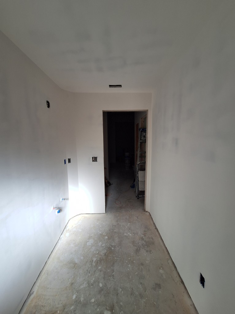
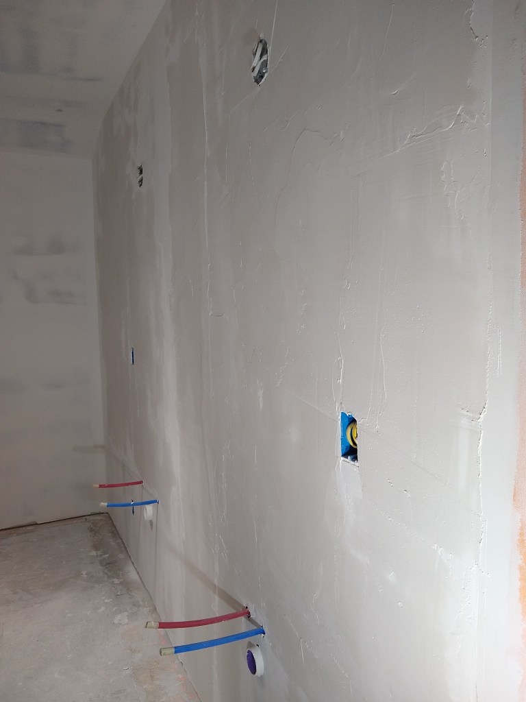
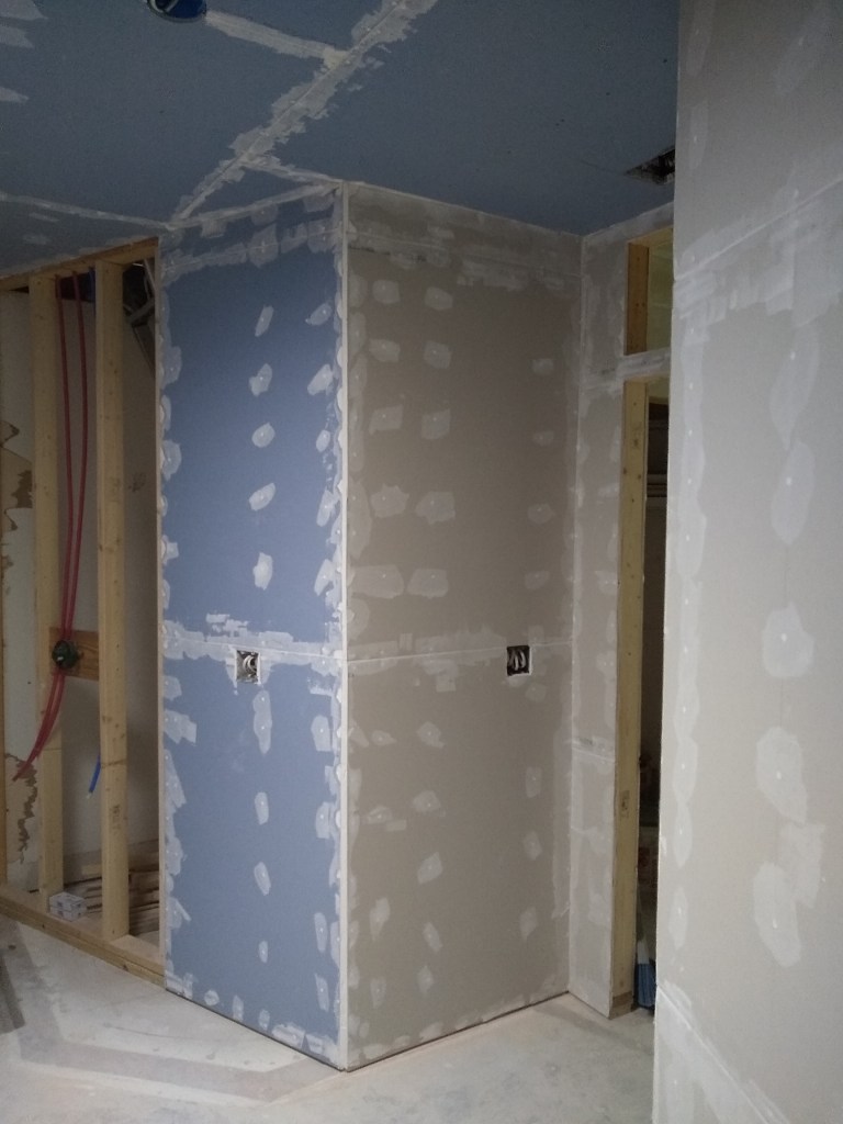
After the second cover coat of the tape, a little more attention is paid to the sanding in preparation for the first skim coat. The idea of skim coating is to cover all the drywall surfaces with joint compound so that the texture is consistent. That is, we don’t want part of the wall covered in joint compound and other parts with none.
First Skim Coat
First Skim Coat
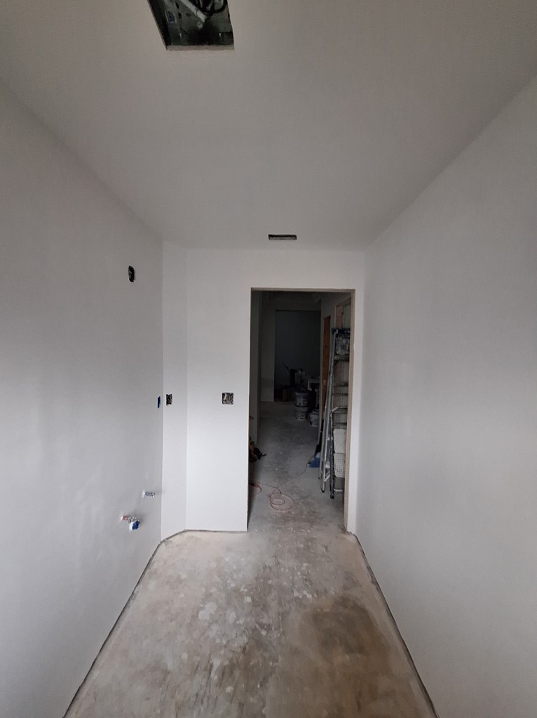
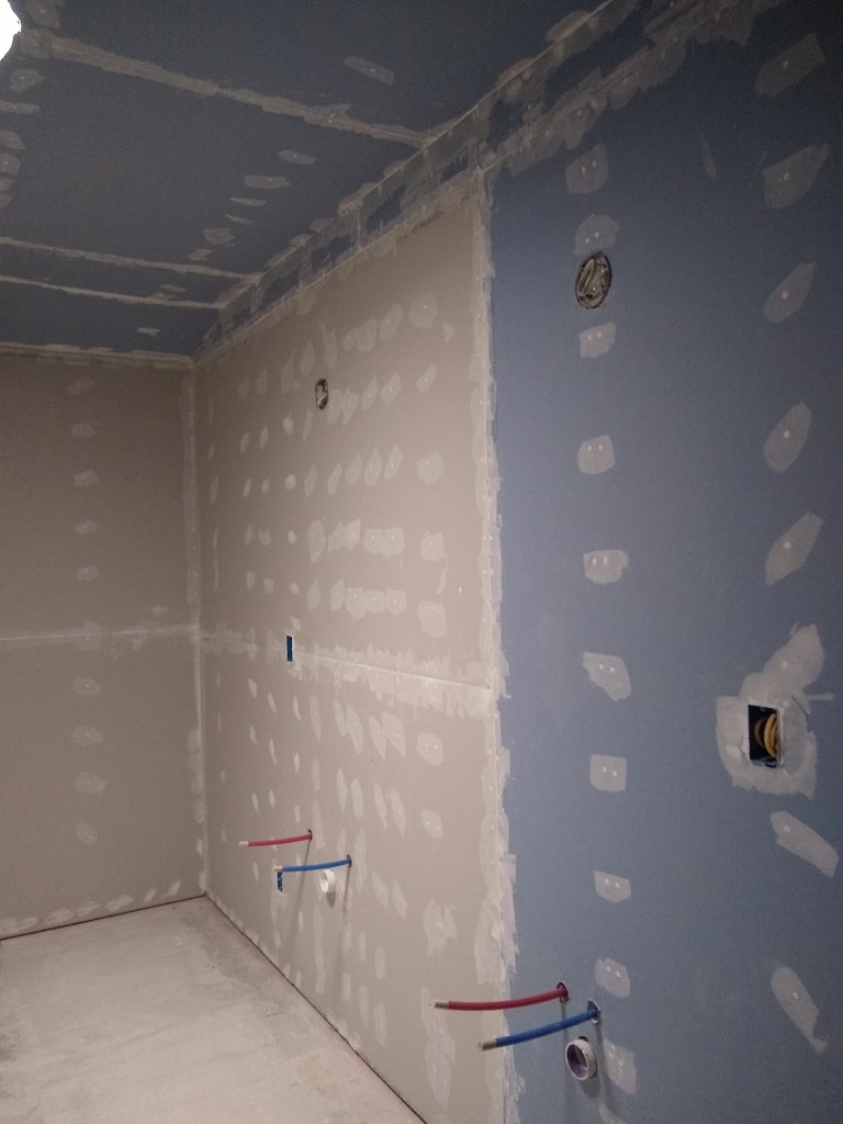
A single skim coat is normally enough, but I like to do a second to ensure there is enough joint compound on the walls (and ceiling) to make an even nicer surface. Before applying the second skim coat, the prep work becomes more important. The more attention I pay to the sanding, the less work I have to do on the second/final skim.
Second Skim Coat
Second Skim Coat
Some serious attention is paid to prep work before applying primer. I hand sand using a hand held light wand to ensure I remove as many imperfections as possible. It is inevitable that I will miss something since everything is white (snow blindness), but if I’m not able to see it with the wand, it is highly unlikely it will be noticed by anyone. Here is the room after applying a single coat of primer to the walls and ceiling.
Primer Applied
Primer Applied
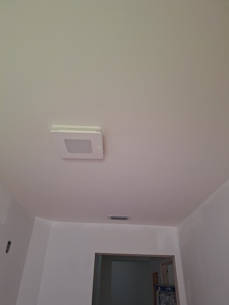
I left the walls with only a coat of primer, since I had yet to choose a wall color. The ceiling, however, would get two coats of white ceiling paint.
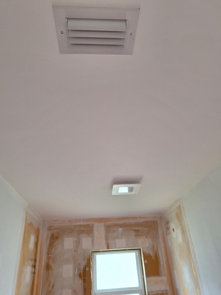
Ceiling Painted
Ceiling Painted
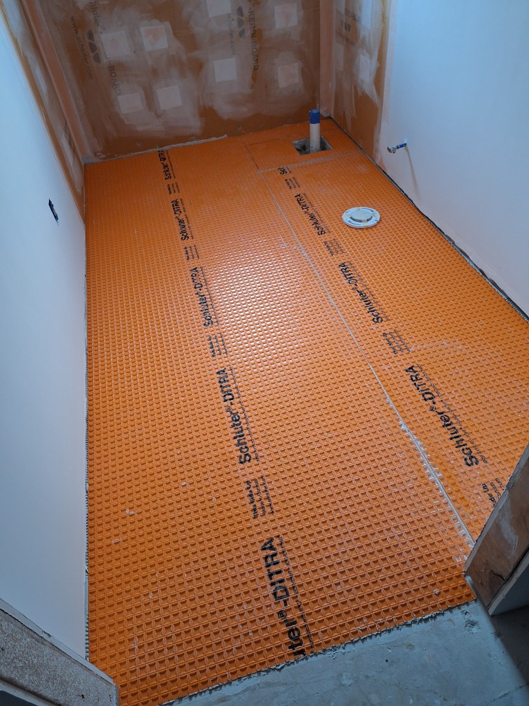
As you can see above, I put the A/C grate back in place after spray painting it to freshen it up, then put up the fan/light fixture. With the ceiling painted, I was ready to put down the DITRA underlayment for the tile.
DITRA Installed
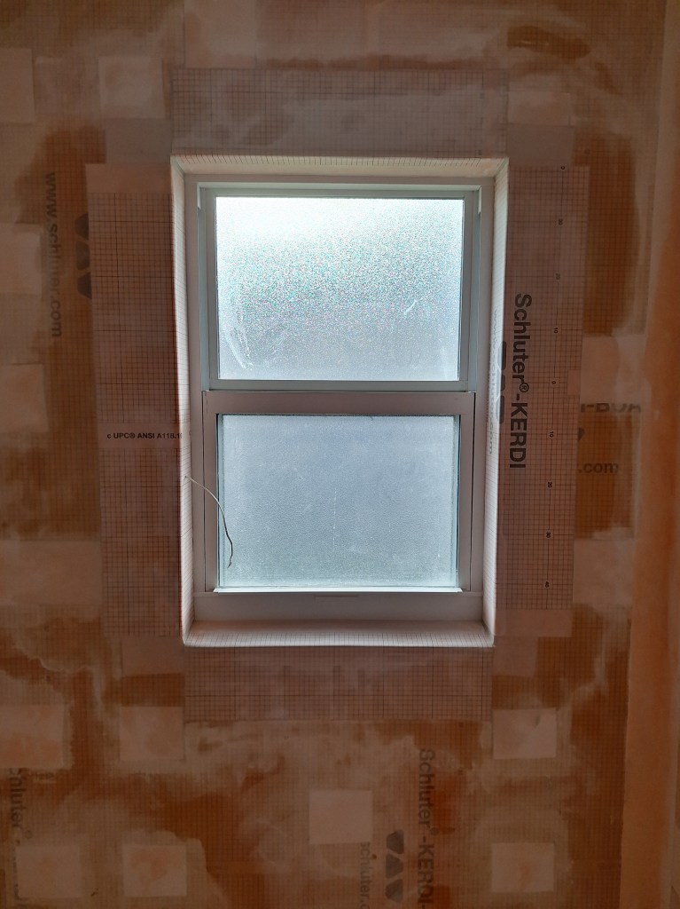
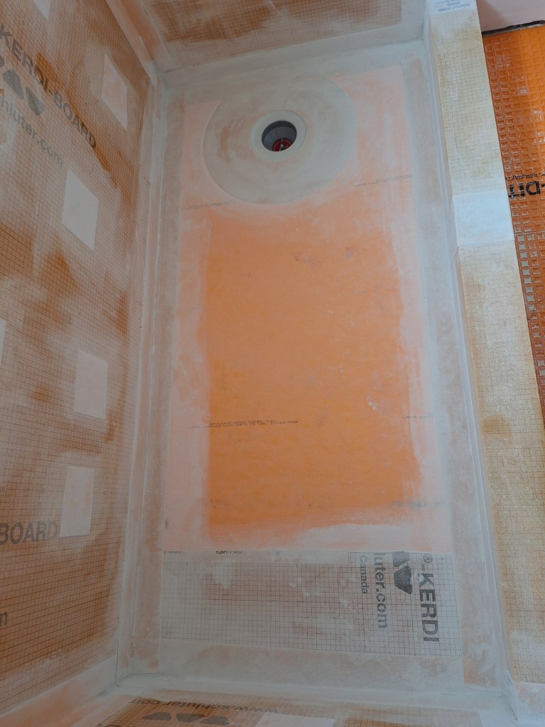
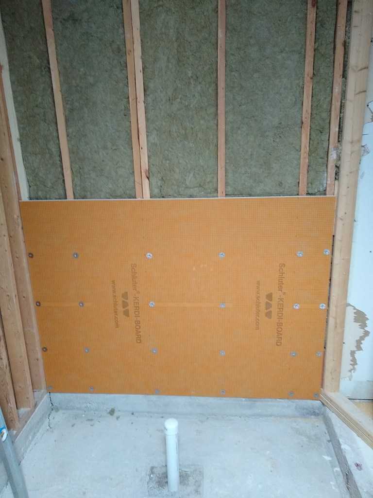
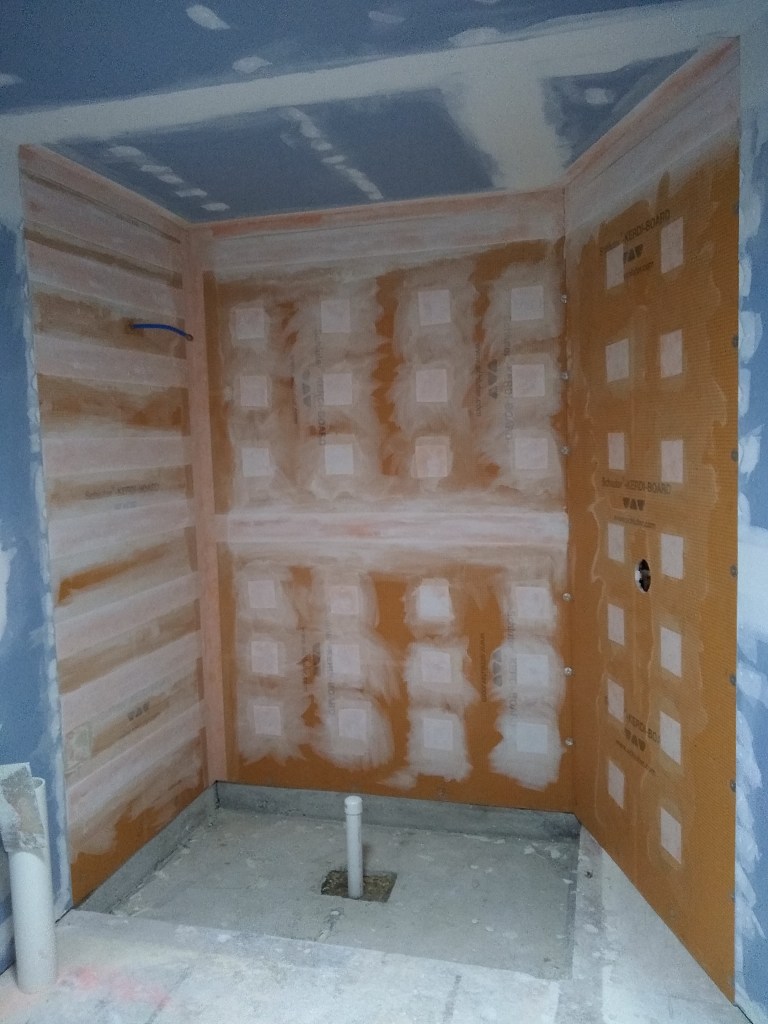
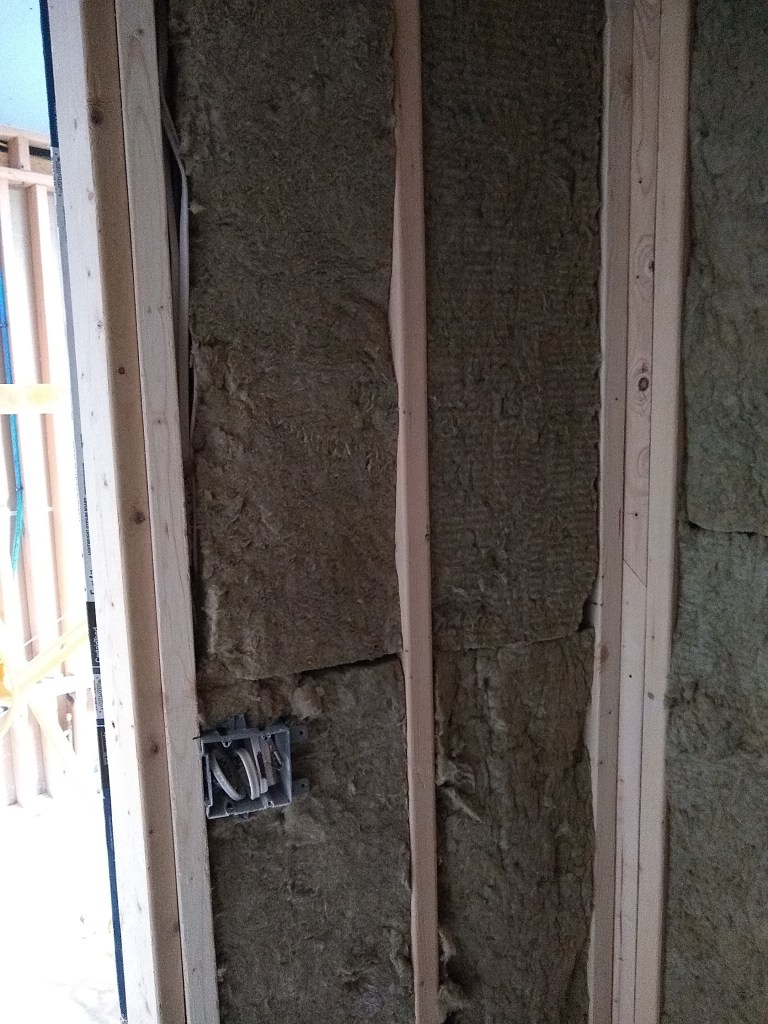
After that I returned to the shower area to waterproof around the window. I figured I would use Kerdi board around the window, but ran into the same problem I had when I put it up on that exterior wall; namely, I needed to build the area out to accommodate the 1-5/8″ screws. Unfortunately, I didn’t have the space around the window to do that, so I had to come up with an alternative solution. Rather than use Kerdi board, which would have added an extra 1/2″ of thickness, I used Kerdi membrane, which added virtually no extra thickness. Let me show you.
Preparing Window for Waterproofing
In the image above, you can see that I added drywall all around the window to provide a flat surface on which to attach the Kerdi membrane. At the bottom, I needed to add some wood so the drywall had something to screw into. Previously there was a marble slab attached directly to the concrete block. Here’s a closer look.
Preparing Stool for Waterproofing
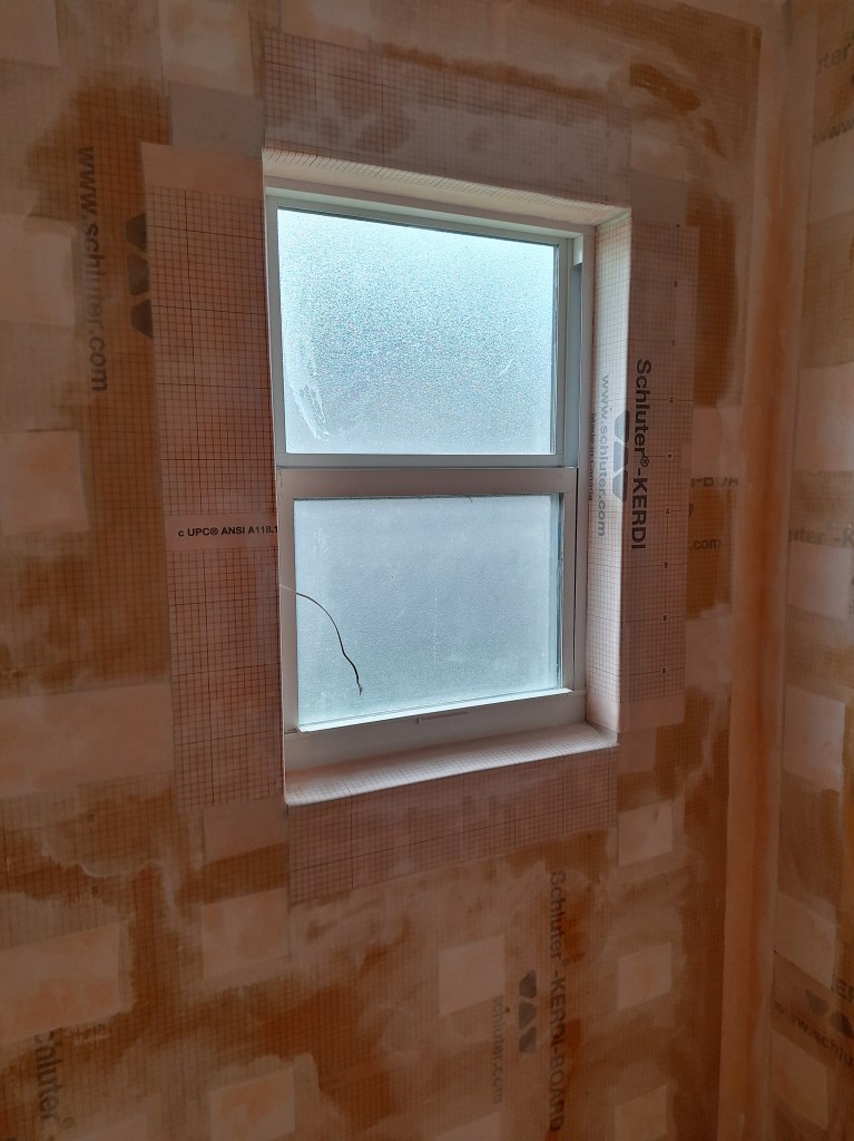
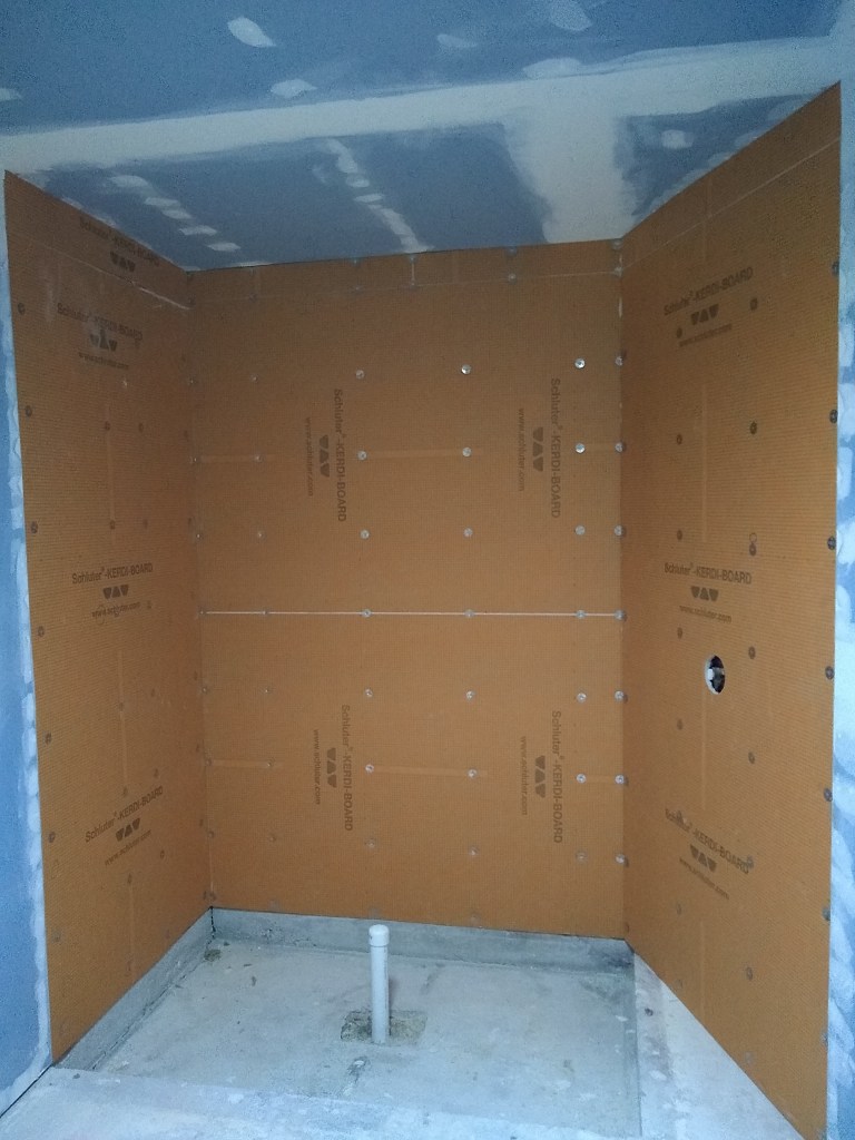
And here it is with the Kerdi membrane added.
Kerdi Membrane Installed
Kerdi Membrane Installed
The wire you see sticking out on the left side is for the security system.
The thing to pay attention to is the space around the membrane and the window frame. It is sufficient to accommodate the thickness of the tile. Had I used Kerdi board, which would have added another 1/2″ of thickness (needed for the 1-5/8″ screw length), I would have had no room for the tile. So this worked well.
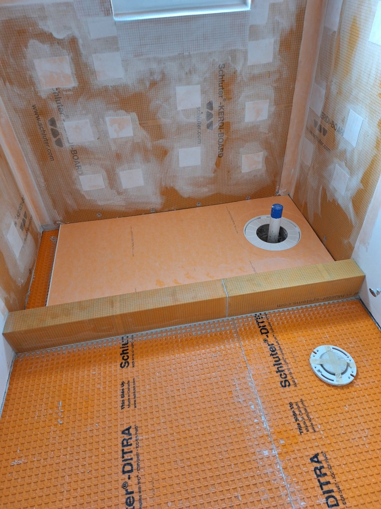
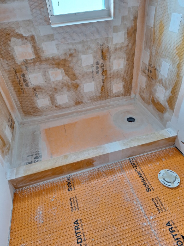
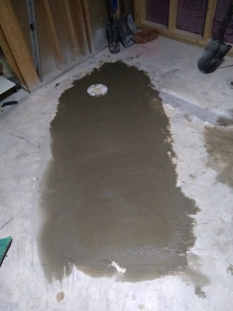
With the walls of the shower waterproofed, I turned my attention to the shower pan. I started by cutting the preformed shower pan and setting it in place with thin-set mortar. This served as a reference for putting the Schluter curb in place. Like the pan, it too was set in place using thin-set mortar. The curb did not come in a long enough single piece, so I had to buy two and butt them together. The seem between the two pieces will be wrapped with Kerdi band, as you’ll see shortly.
Pan and Curb Installed
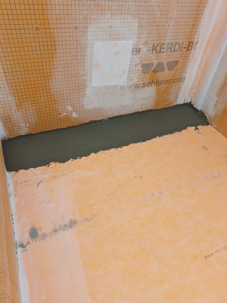
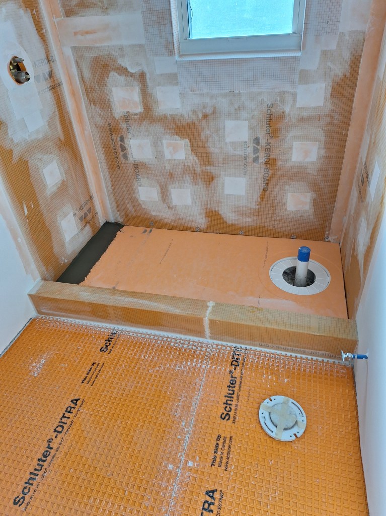
The pan was not long enough to fit the space, so I filled in the gap on the left with drypack mortar. Once dry, it will be covered with Kerdi membrane to make it waterproof.
Pan Extended using Drypack Mortar
Shower Pan before Drain Flange Installed
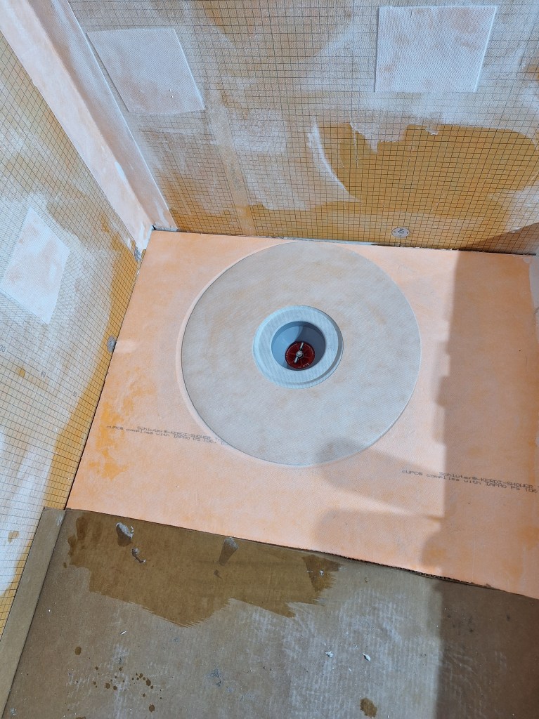
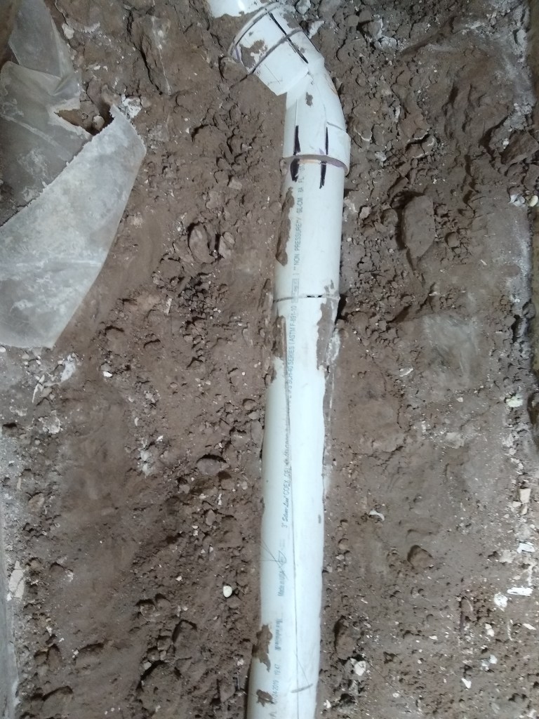
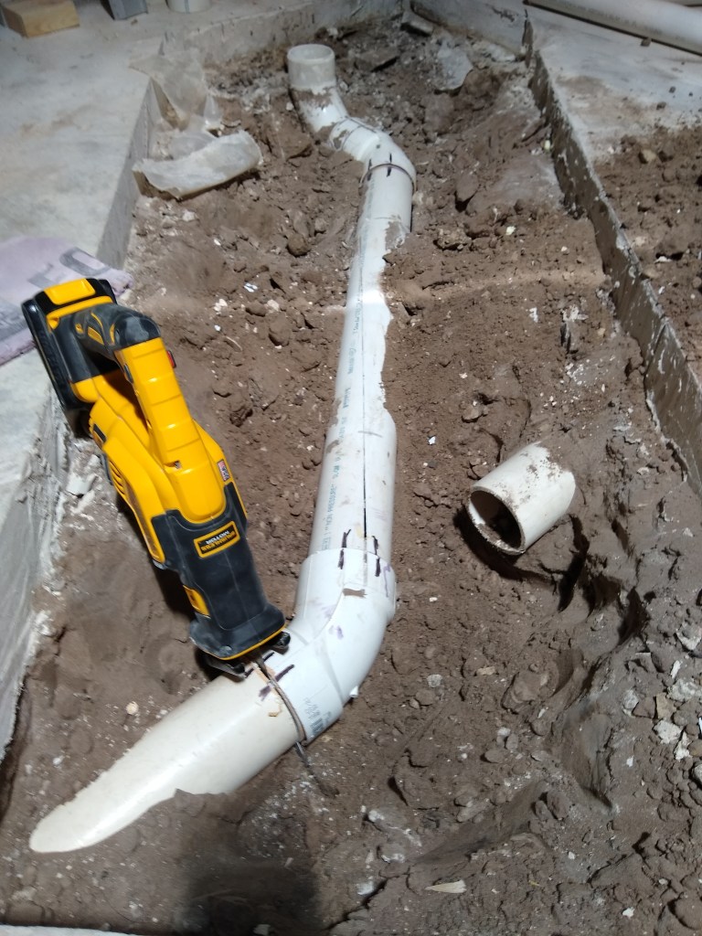
I actually made a mistake by putting the pan down first. What I should have done was set the drain flange in place before setting the pan. In the end it wasn’t a big deal, but it got in the way as I was setting the drain flange. When I did the master shower, I set the drain flange first. For this shower, I simply forgot the order of operations. Another thing that caused me some grief, was that the p-trap needed to be lower than it was. This was a rookie mistake. Although I did check the depth and was comfortable that it was low enough, I did not give myself enough room for error. Without intervention, it would have left the drain flange about 1/2″ above the shower pan. I should have placed the p-trap low enough that there would be no question of the drain flange sitting too high. To sort this out, I had to completely remove the riser pipe (the one with the blue tape covering the opening), then cut off some of the flange where it connects to the riser pipe to bring it down to where it needed to be. I used a 1″ length piece of 2″ diameter PVC to join the two. This was long enough to bring the two pieces together and still have sufficient “bite”, but I was lucky. Anything less, and I would have had to undergo a much more severe operation. This stressed me out. I was relieved to be able to sort it out without any major surgery. Here is the drain flange installed and waterproofed.
Drain Flange Installed and Waterproofed
After that, I added Kerdi membrane over the drypack extension and over the remaining seems.
Shower Pan Waterproofed
The seem between the two sections of curb was also wrapped.
Shower Pan Waterproofed
Once the thin-set used to set the Kerdi band was dry, the shower should be waterproof. To ensure this is the case, I filled the shower pan with water and left it overnight.
Shower Pan filled with Water
After I was confident there were no leaks, I scheduled another inspection so the inspector could witness that this had been done, which went without issue.
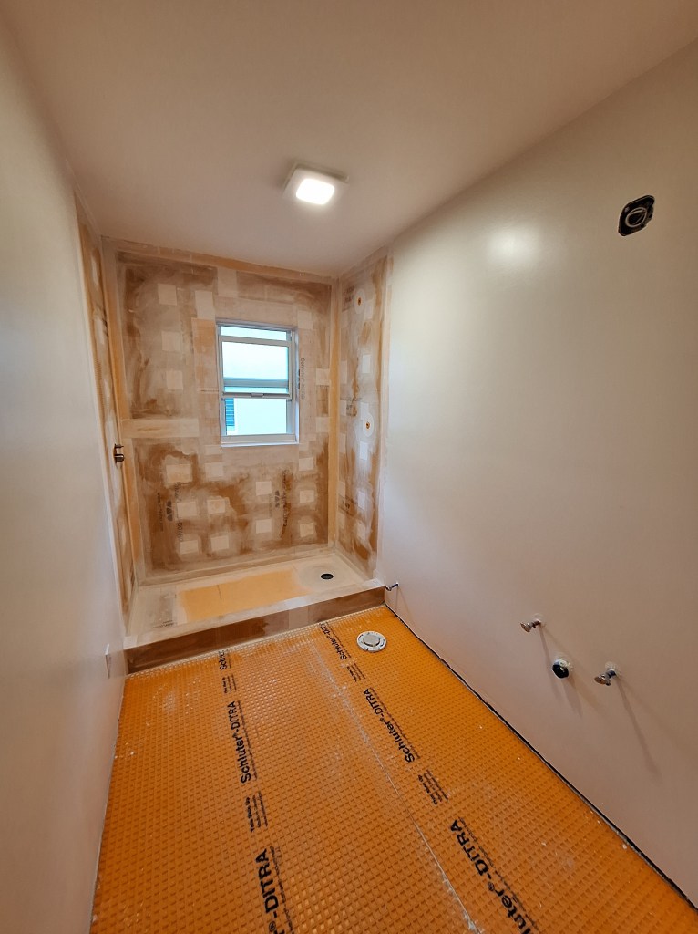
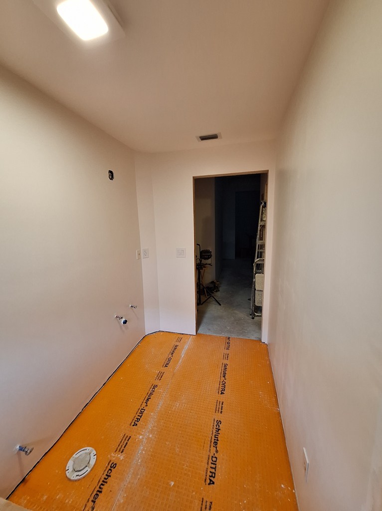
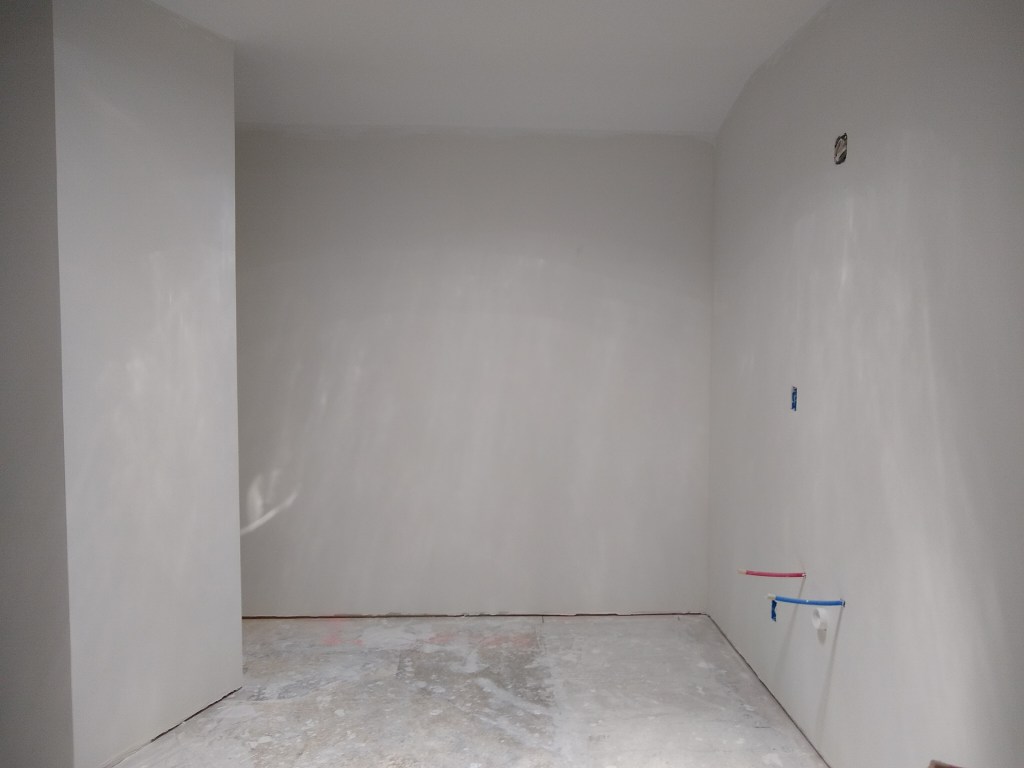
With the water test inspection done, I was free to tile away. However, I had yet to select the tile I would use. I spent some time exploring this, but in the end decided to use the same scheme I used in the master bathroom. I know that is not very adventurous, but I really liked that scheme and did not want to risk introducing something I might regret later. So I placed the order and then had to wait for them to arrive. In the meantime, I decided to paint the walls and install the switches and outlets. As in the master bathroom, I used the Behr equivalent of Sherwin Williams’ Alabaster with a satin sheen.
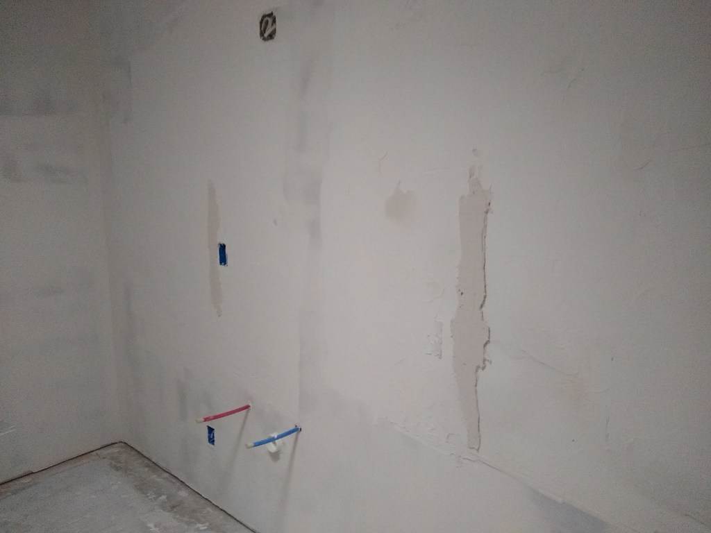
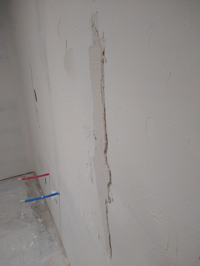
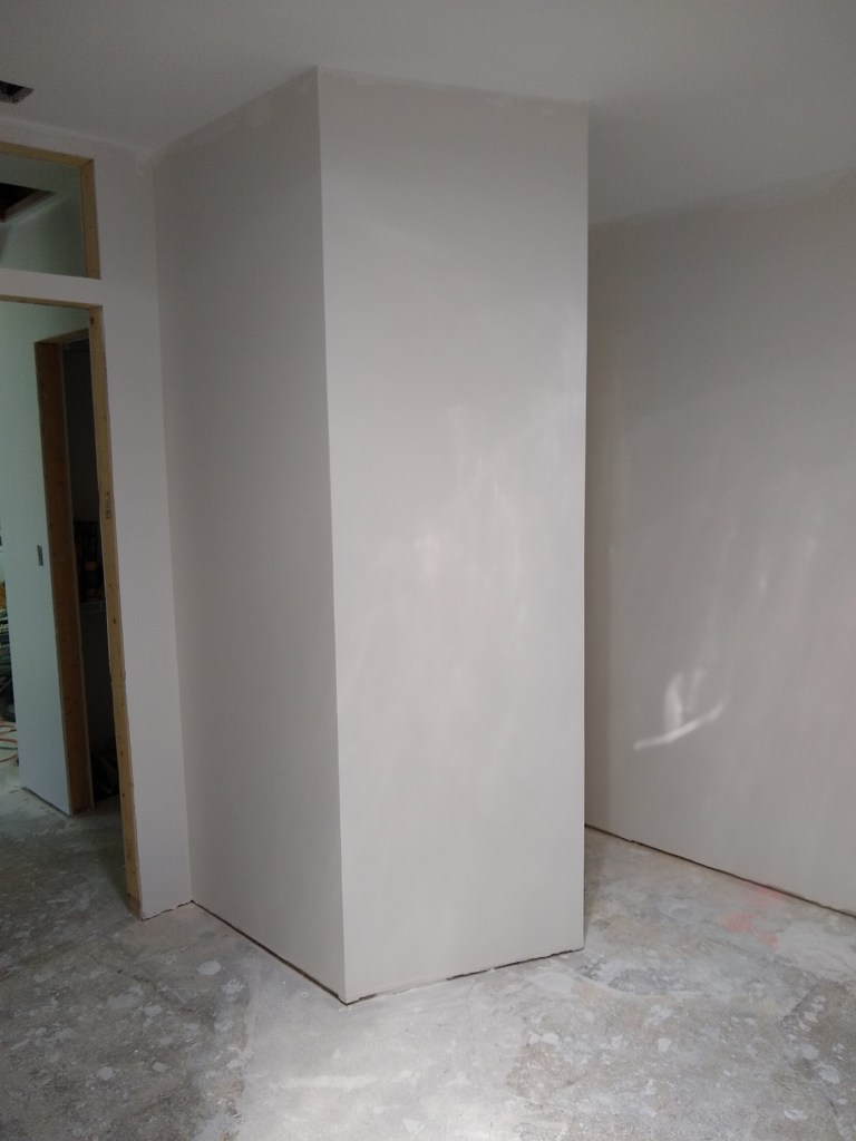
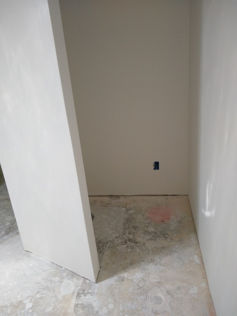
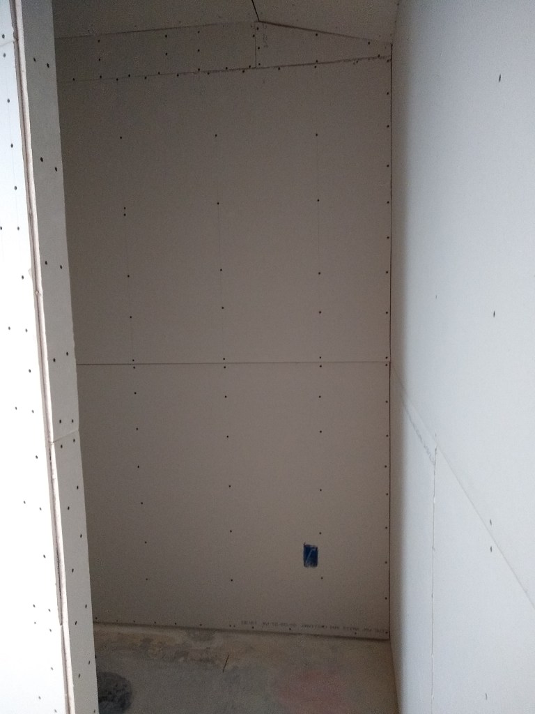
Walls Painted
Walls Painted
With the switches installed, I can now illuminate the room with the light from the vent fan. The vanity lights have yet to be chosen, so that junction box remains exposed. I also added the face-plates for the Ethernet cables.
I had intended to continue this post with at least the floor tile and shower floor tile installed before I stopped work for the holidays (mid-December), but tiles took longer than expected to arrive and I got extremely busy with social commitments. Fortunately, this down time worked to my advantage with respect to the social commitments, giving me the time I needed to attend to them. At the time of writing, I have just over a week before I go away for the rest of the month, returning after the first week of January. With more social commitments upcoming (it’s the holiday season, after all) I’m not confident I will be able to do anything more before I leave, so I will end the post here. If I do manage to do anything before I leave on vacation, it will appear in my next post.
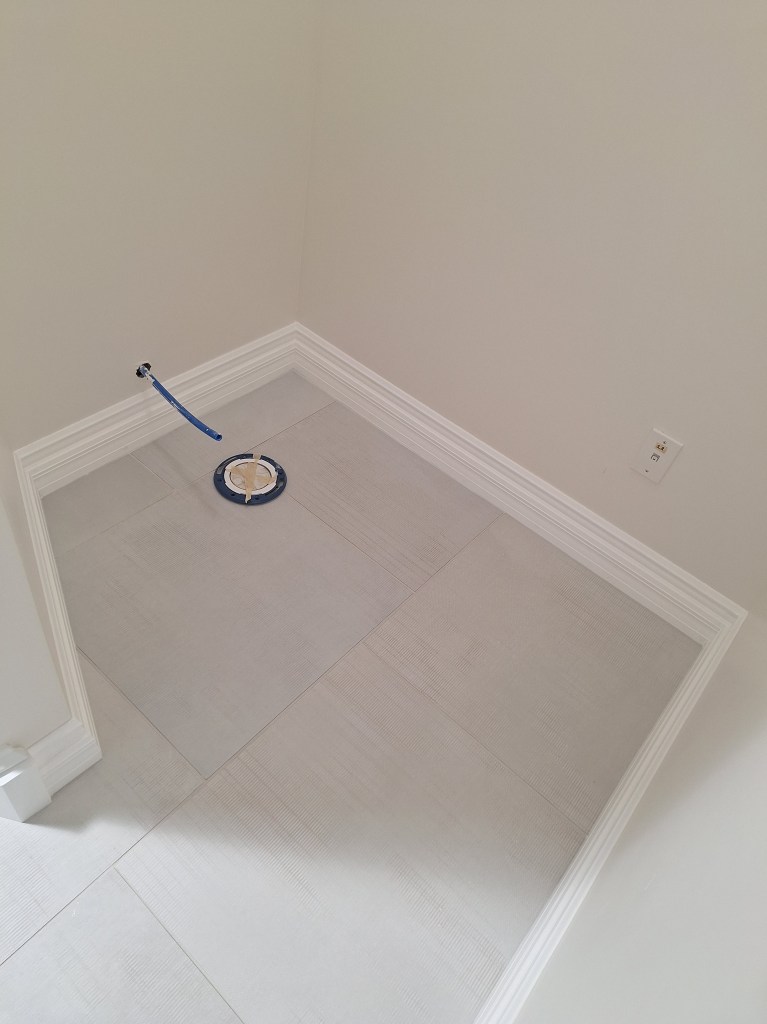
In my last post about the master bathroom, I had picked up the baseboards and glued together the two pieces that would form the whole. They were now ready to be installed. I did this along the long walls first, then went into the toilet alcove, where I had a bit of an issue that was a consequence of a poor job of tiling that area. Recall that I had to wait on new tiles to finish that area. When I got back to it, I focused my attention on making sure they aligned well enough with the existing tiles. I didn’t think about whether they were sloped or not. Unfortunately, there was a slope, and one that was too large to ignore. Even though the gaps were behind where the toilet would be, and therefore not especially obvious, I still wanted to see what I could do with them to make it less obvious. So I cut out and fashioned a couple of custom strips of wood and glued them in place to fill the gaps. Although I don’t have a “before” picture, you can see from the strip I put in, that it was not trivial.
Filler Piece Added to South Wall of Alcove
Filler Piece Added to East Wall of Alcove
Once the glue dries and they area caulked and painted, they will look much better and be virtually invisible.
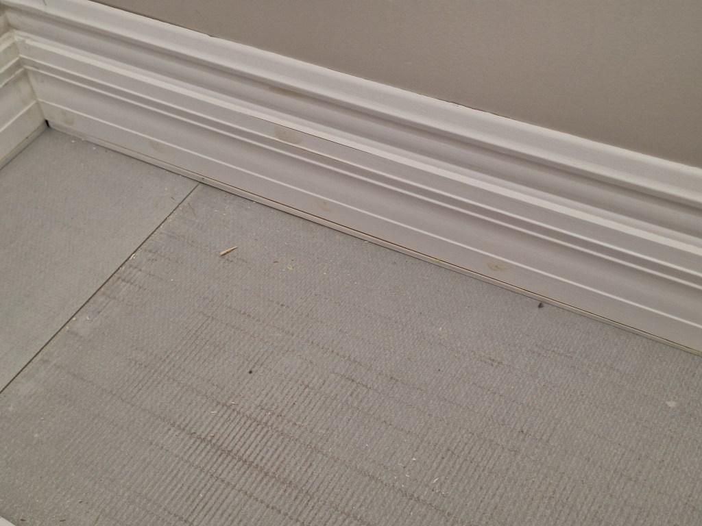
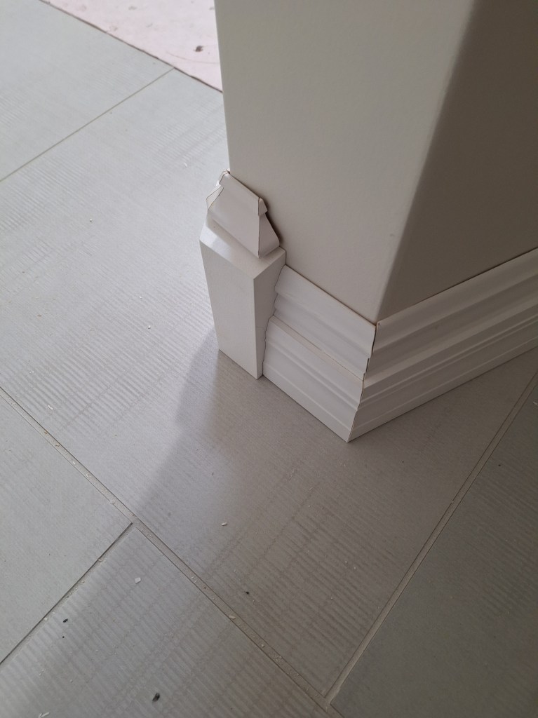
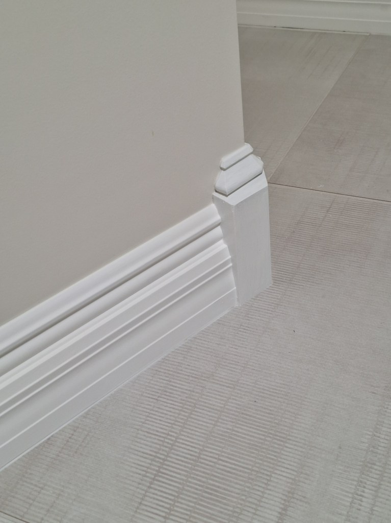
As you come out of the alcove, the wall makes a turn that produces a rather sharp outside corner. The angle here is 68 degrees. Cutting the baseboard in the usual way would make this a very pointy outside corner, and one that would be susceptible to damage. So I explored creating a three piece outside corner, kind of like what you see below.
Baseboard – A three piece outside corner.
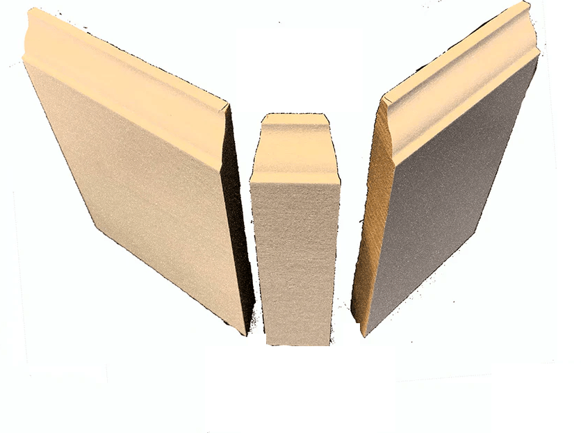
However, after many attempts and modeling in SketchUp, I could not get this to work. I believe this is because I have such a complicated profile, a more acute angle, and a sharp (not bull-nose) corner. The situation shown above is intended to deal with a bull-nose corner. It’s pretty simple because the angle is 90 degrees and most of the baseboard is flat. At least that is my sense of it. Perhaps one day I’ll figure it out. Unfortunately, I could not find anything online to show how to deal with such a situation, which made me feel like it wasn’t doable. So I needed an alternative. I decided to create an outside corner block. Kind of like this.
Baseboard – Example of an Outside Corner Block.
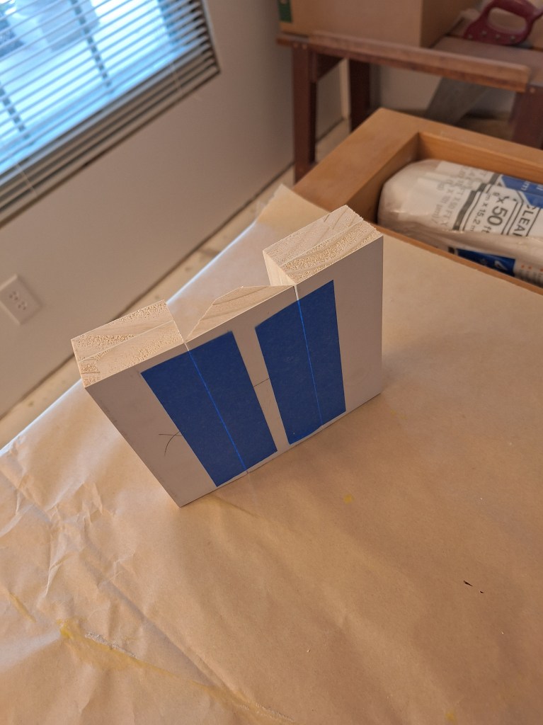
So I started building one. Here are the three pieces before gluing them together.
Baseboard – Outside Corner Block Pieces before glue-up.
Baseboard – Outside Corner Block ready for glue-up.
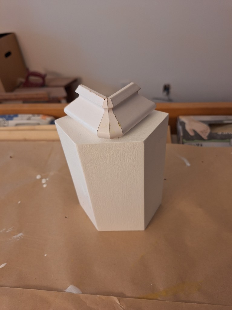
The two outside parts of the block are built up from two thinner pieces of stock in order to give them some heft. The middle piece ties them together as you can see below after I glued the three pieces together.
Baseboard – Outside Corner Block after glue-up.
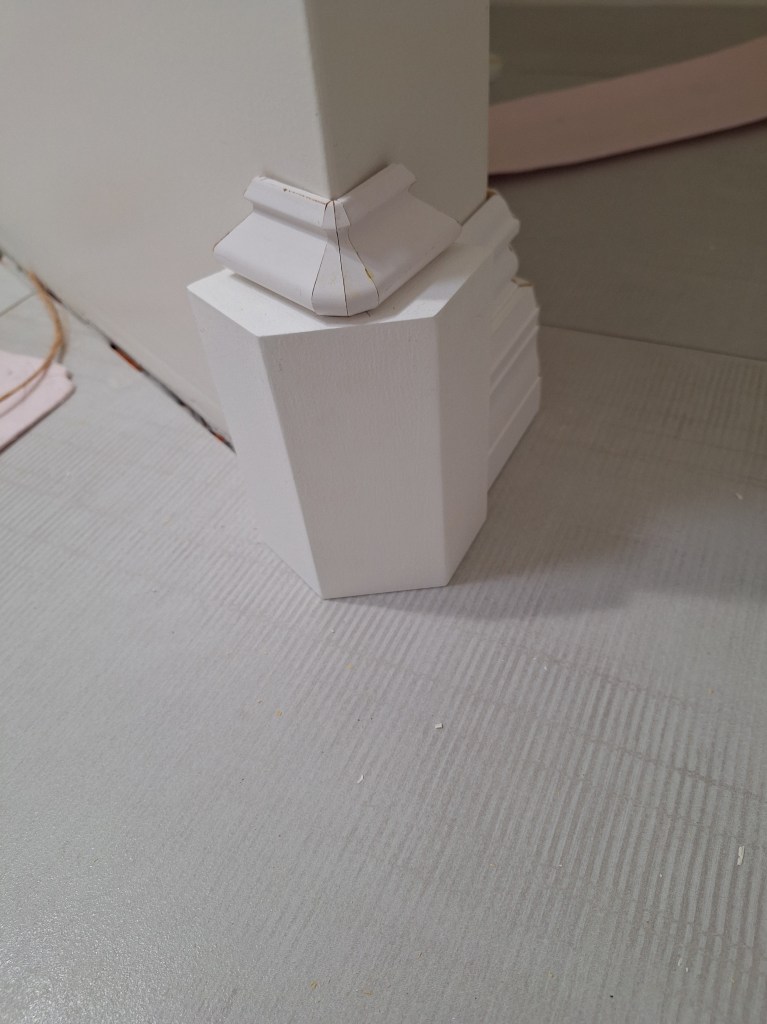
With this arrangement, I can simply butt the baseboard to the ends of this corner block. The corner block presents a flat face as you round the corner, making it more resilient to knocks. To dress it up a little, I added a decorative top using basecap. Here it is in the raw.
Baseboard – Outside Corner Block with Basecap.
The block part is painted, but the basecap is not. In this image, I had just glued it together and placed it on top of the block. I then put it in position without fastening it to see how it looked.
Baseboard – Outside Corner Block test fit. View from inside alcove.
The short piece of baseboard that butts up to it in the image above is not fastened either. I just placed it there to see how it looked.
Baseboard – Outside Corner Block test fit. View from outside alcove.
The basecap is not as flush with the wall as I’d like, but it was very tricky to get those angles perfect. To get it to fit just right, I’d have to modify the angle of each of the four pieces by a small fraction of a degree. You can’t just modify one of them because the profiles won’t line up. I decided not to risk it and will let the caulking fill those gaps. It’ll look just fine.
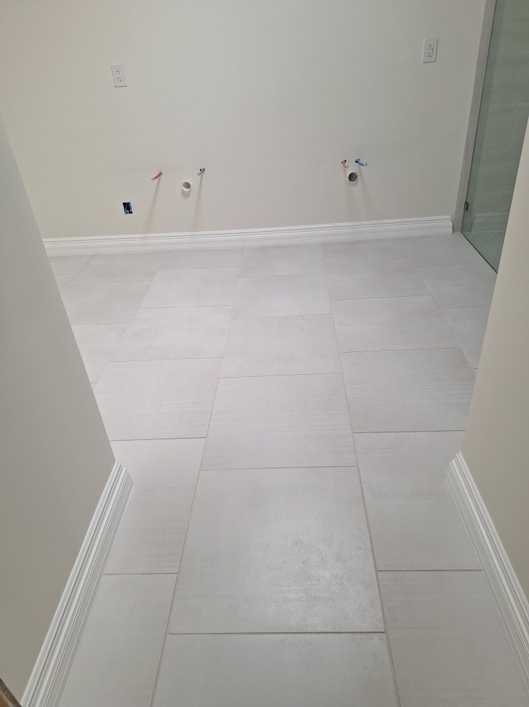
After a bit of sanding and painting, the corner block was done and I could finally finish the baseboard installation. Here are several shots from different angles.
Baseboard – From Entrance.
One could question the value in putting baseboard along the entire length of the vanity wall, since most of it will be covered up by the vanity. My vanity has legs, so if you get down low enough you can see it. So I decided just to do it.
Baseboard – Toward Entrance.
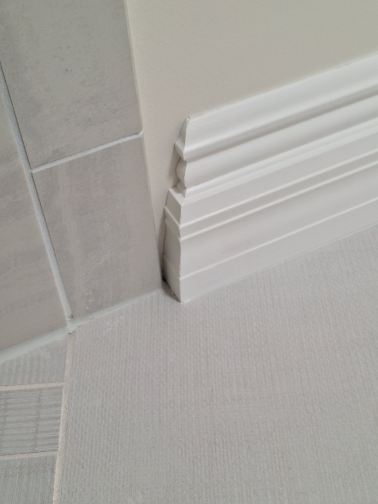
Where the baseboard meets the tiled shower walls, I added a return to terminate it nicely. Here’s a closeup of one of them.
Baseboard – Closeup of Return.
Baseboard – Toward Toilet Alcove.
In the above image you can see the outside corner block and how the baseboard ties into it. Here are some closeups.
Baseboard – Outside Corner Block.
Baseboard – Outside Corner Block.
I think it looks pretty good and will stand up much better to knocks than if I’d mitered the two pieces at that corner. And here’s a look inside the toilet alcove.
Baseboard – Toilet Alcove.
In the image above you can also see the toilet flange I had just installed in preparation for the toilet, which I did next. Here it is.
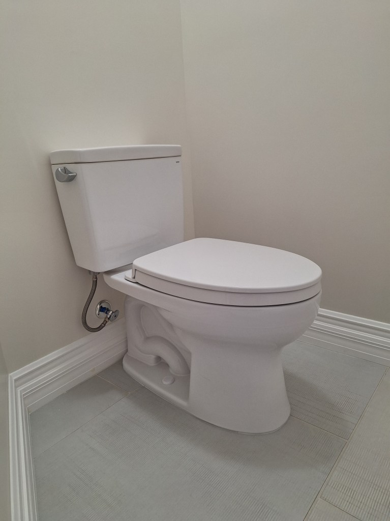
Toilet Installed.
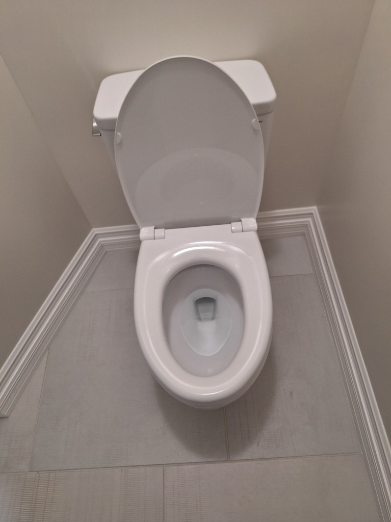
And here’s one with the seat up. Sorry, just clean water in there.
Toilet Installed.
This was my very first toilet installation. It was all new to me, and I got kind of lucky with it. The toilet only just fit. The center of the toilet flange is supposed to be 12″ from the finished wall. Mine was 11 1/2″, which was a mistake due to not taking the thickness of the drywall into account. Online, some people claimed they prefer to use 11 1/2″ to get a tighter fit, which gave me some relief back when I first realized my mistake. I was hopeful I would get away with it. In the end, I did, but 11 1/2″ was not appropriate here. I had no wiggle room at all. The back of the toilet is right against the wall, and with my rather beefy baseboards, there is only about 1/8″ of clearance between the baseboard and the base of the toilet. Another stroke of luck was that the tank lid is the same size around as the tank. In my experience, is not that common. I’m used to it being larger, like a lid of a jar. Consequently the lid fits on the tank as intended.
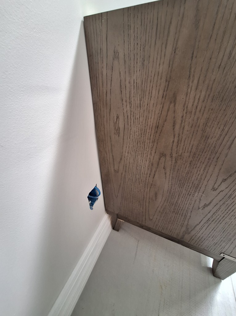
With the baseboard done and the toilet installed, I could now move the vanity into place. Upon doing so, I discovered that I could not push the vanity right up to the wall. The back legs were directly inline with the back of the cabinet rather than inset. Consequently, the thickness of the baseboard prevented it from lying flat against the wall. There was about an inch gap.
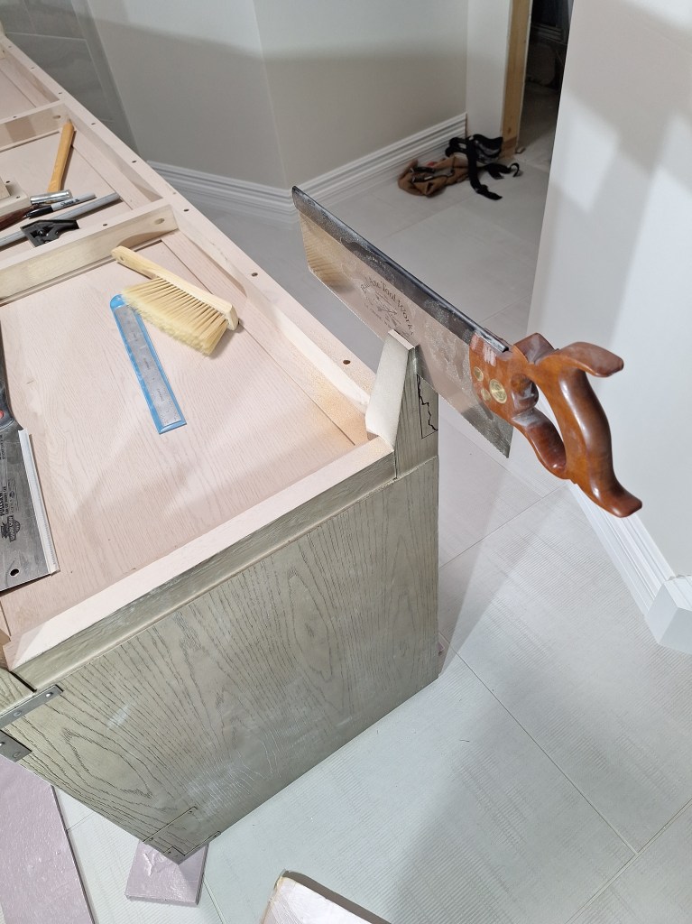
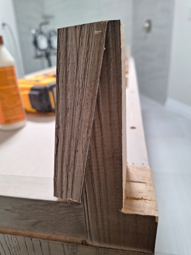
I turned the vanity upside down on the floor to explore my options. I was hoping the legs would come off and that I could reposition them, but wasn’t optimistic about that. Since the vanity is quite heavy and would require very sturdy legs, simple screw-in legs were unlikely, which was what I discovered. I also considered cutting the baseboard just enough to let the feet slide in, but I wasn’t keen on that. The baseboard should not need to accommodate the vanity. One day I may decide I want to change it out for another one. In the end I decided to modify the back legs of the vanity to accommodate the baseboard. So I marked out what I wanted to cut, and got started.
Modifying Vanity Back Legs – Start the Cut.
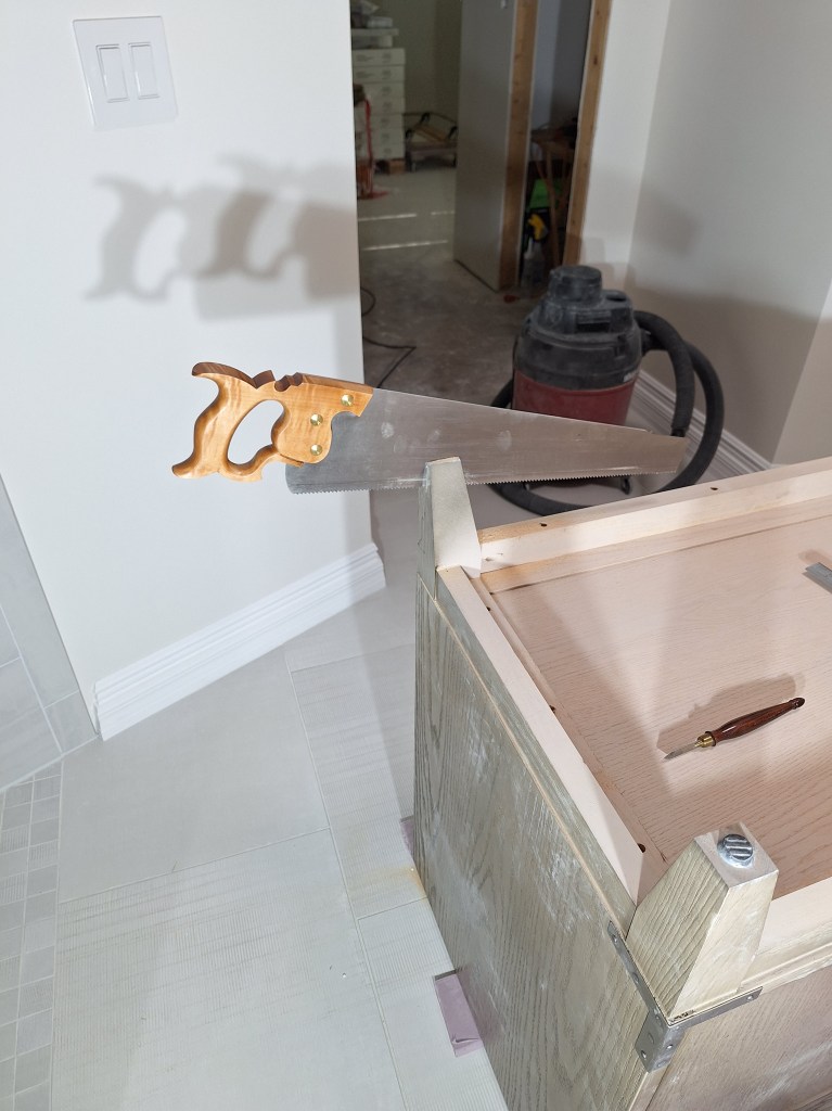
In the image above you can see how I traced out the baseboard profile in order to minimize what needed to be cut (keep in mind it is upside down). I wanted to preserve as much of the foot as possible, which wasn’t very much. I started my cut with a back saw, but had to complete it with a panel saw because the plate of the back saw could not take it all the way. The image below is of the other leg.
Modifying Vanity Back Legs – Panel Saw used to complete the Cut.
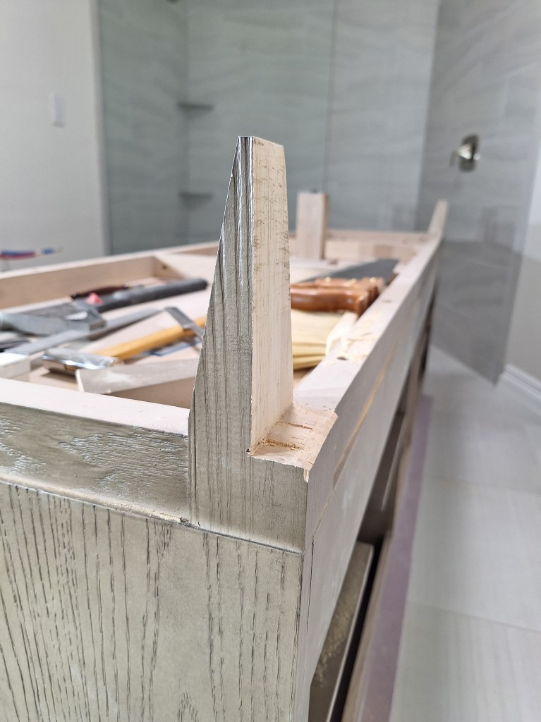
Once the cut was complete and cleaned up a bit with a chisel, it looked like this.
Modifying Vanity Back Legs – Cut Complete, side view.
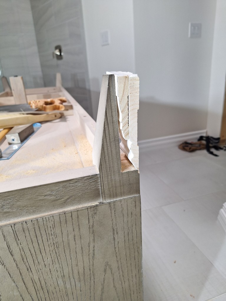
Modifying Vanity Back Legs – Cut Complete, back view.
Here is a shot with a piece of baseboard held up to it so you can see how it fits.
Modifying Vanity Back Legs – Baseboard Test Fit.
There will be a screw-in pad under the leg, so there is plenty of room for the baseboard.
Although the back legs look like stiletto heals, they are quite strong. They are made of solid wood, so once the vanity is in place, it would be well supported with just that amount of wood. However, I would be less confident if it was moved around a lot. So I decided to use the off-cuts to bolster them. Each leg received the off-cut of the other in order to keep the finished side out. Although you have to go out of your way to see these legs, this makes them less conspicuous should you try.
Modifying Vanity Back Legs – Bolstering, show side.
Modifying Vanity Back Legs – Bolstering, hidden side.
These were attached with glue and brad nails, which was plenty. However, I decided to add a wedge to fill the gap, just to be extra careful.
Modifying Vanity Back Legs – Support Wedge.
Although the support wedge is a different color, it is set in a bit, so from above it is not visible.
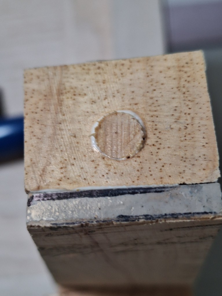
I then plugged the hole at the bottom that would receive the plastic pad. I couldn’t simply reuse the existing hole because it was angled. So I glued a dowel in and let it sit overnight before drilling a new hole that would go straight down.
Modifying Vanity Back Legs – Plugging hole for Plastic Pad.
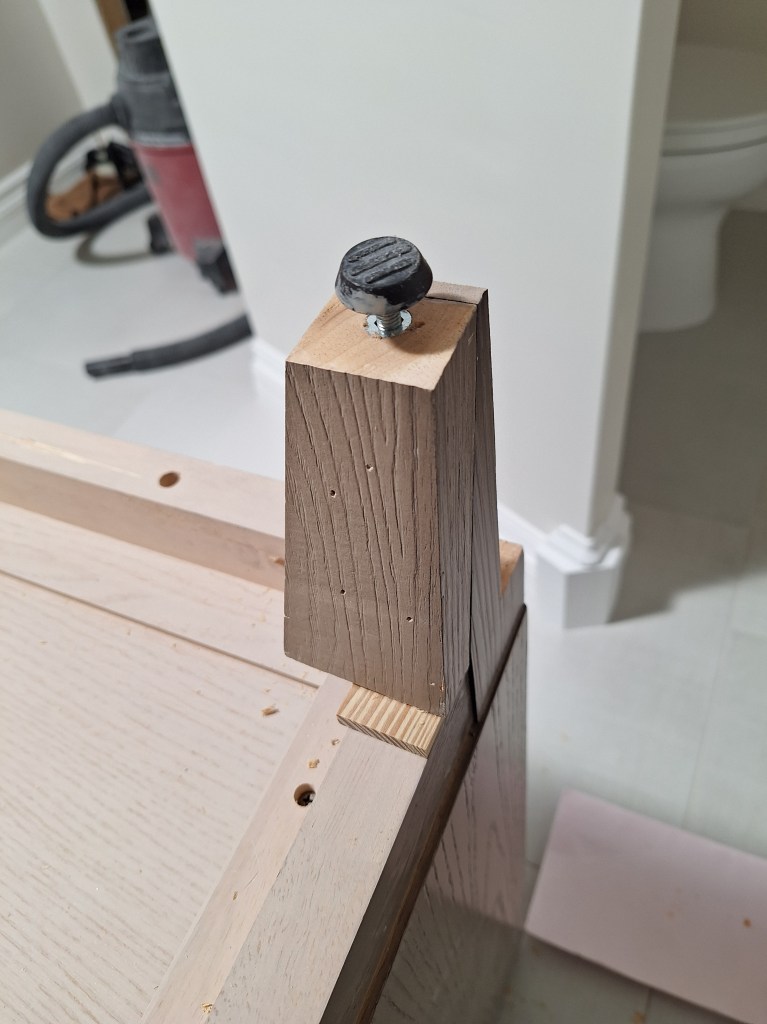
The new hole was then drilled and the threaded insert put into the hole, followed by the plastic pad.
Modifying Vanity Back Legs – Plastic Pad Added.
After both pads were added to the modified legs, I was able to move the vanity cabinet into its final location.
Vanity in Place
The blue tape on the wall marks the center between the where the vanity lights will go. It is now sitting flush with the wall, as you can see below. The vanity will not be fastened to the wall. It will simply sit against the wall like a dresser in the bedroom. It’s very heavy, especially with the marble top, so I am not concerned about it shifting if it is knocked.
Vanity now tight to the Wall
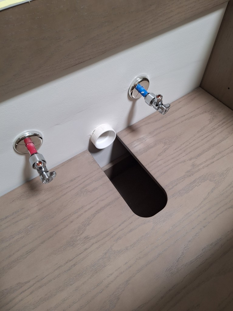
I also added the angle stops for the sink supply lines.
Angle Stops for Left Sink
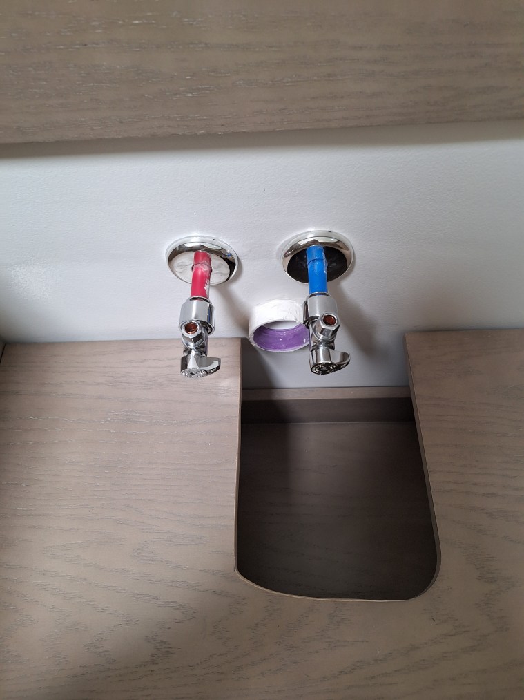
I had to widen the opening in the shelf below the right sink to make room for the the drain.
Angle Stops for Right Sink
The next task with respect to the vanity, was to put the marble top in place. It is a massive thing and something I could not do on my own. With the help of a couple of neighbors, we managed to put it in place.
Marble top Installed
The backsplash came in two pieces that simply butt together. Unfortunately, one of them was not quite square, so when I pushed them together, there was a gap. I used my angle grinder to straighten it, after which they came together nicely. I used silicone to secure it to the marble top, then applied a bead of silicone at the seem between the top of the backsplash and the wall. That should hold it. I didn’t want to apply silicone to the back of the backsplash to adhere it to the wall because I wanted to minimize any damage to the wall should I choose to change out the vanity some day. If I ever did need to remove the backsplash, the bead of silicone between it and the wall would only require minimal repair to the drywall, if any.
The faucets were added next.
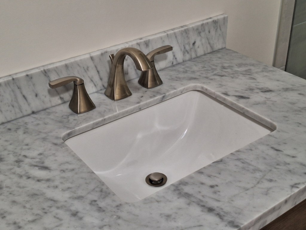
Faucets Installed.
Closeup of Faucet and East Sink
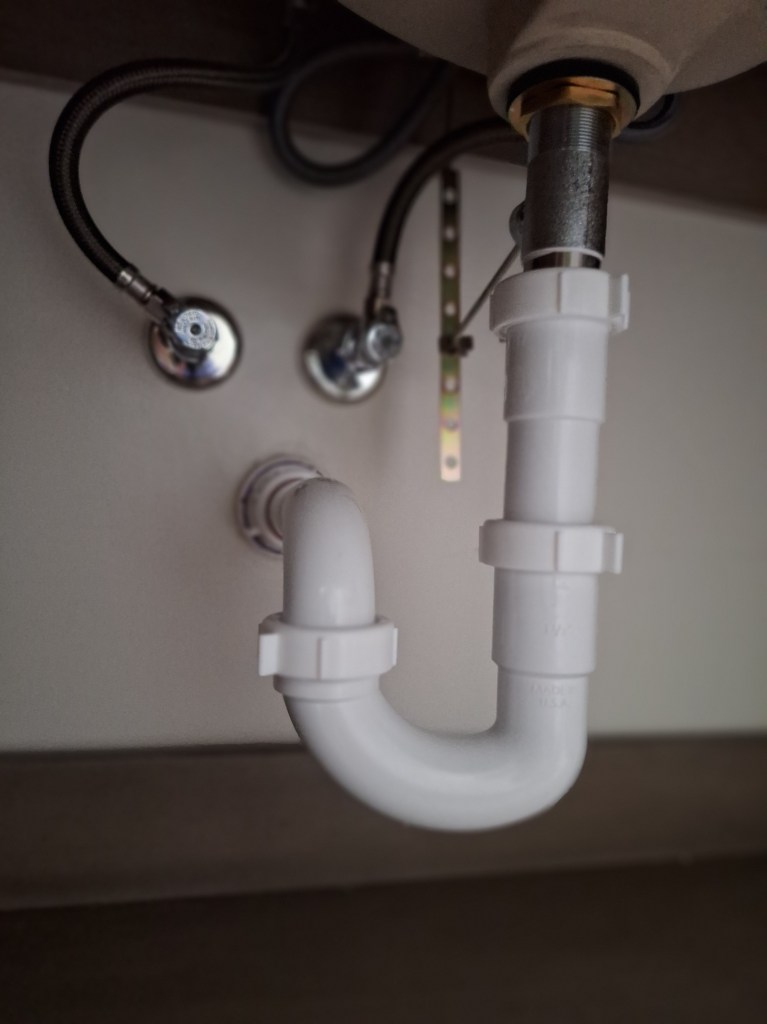
After that, the drain and supply lines needed to be hooked up.
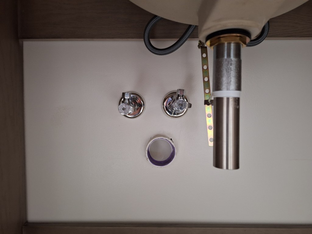
West Sink Before Hookup
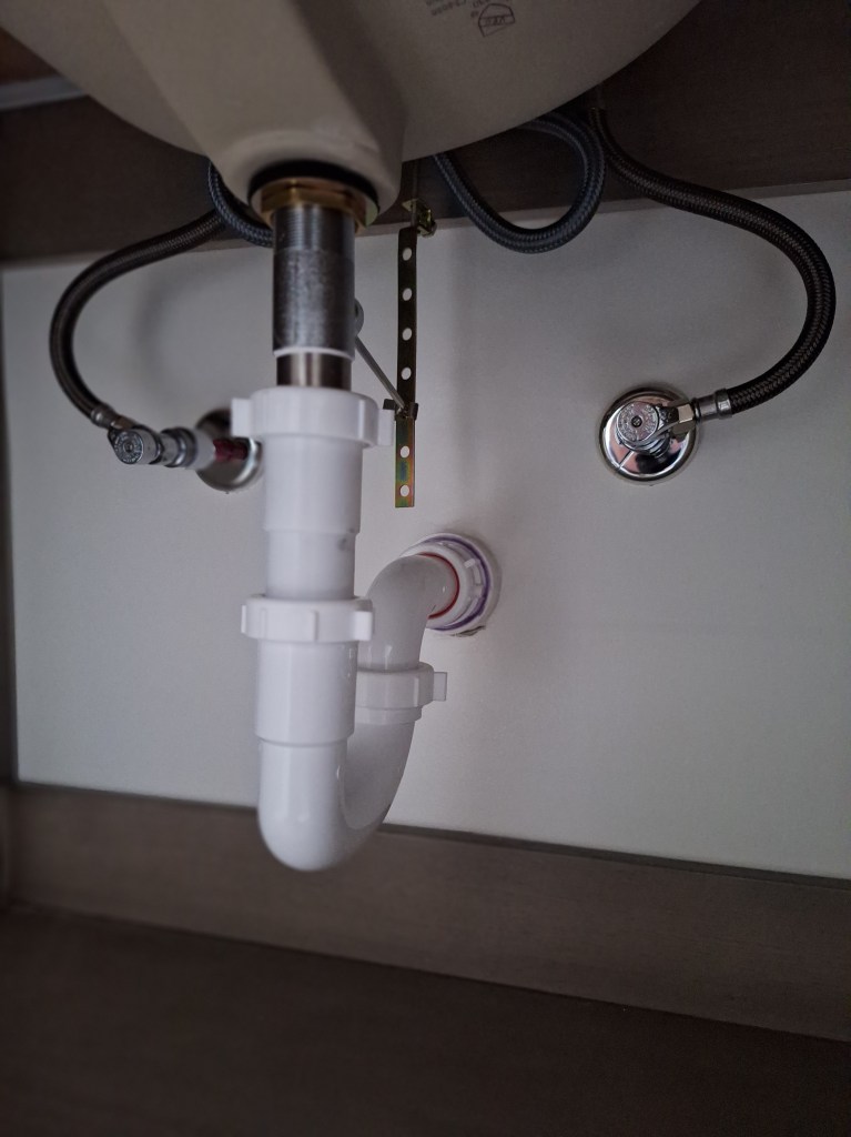
West Sink After Hookup
East Sink Before Hookup
East Sink After Hookup
With that done, I now have a functioning bathroom. The vanity lights and mirrors still need to be added, along with other bits and pieces (like towel rods, etc.). At the moment I’m not sure whether I want to have a single large mirror or two smaller ones. Decisions like this can be made much later, even when I’m living in the house, so I will put them off so that I can start work on the guest bathroom.
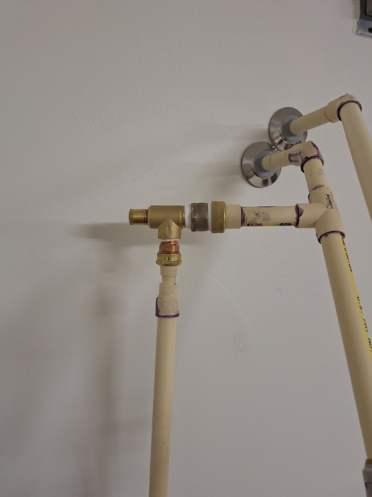
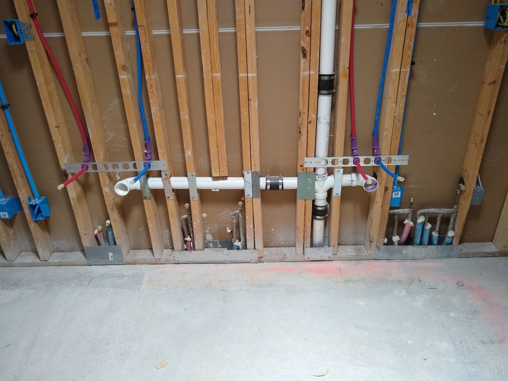
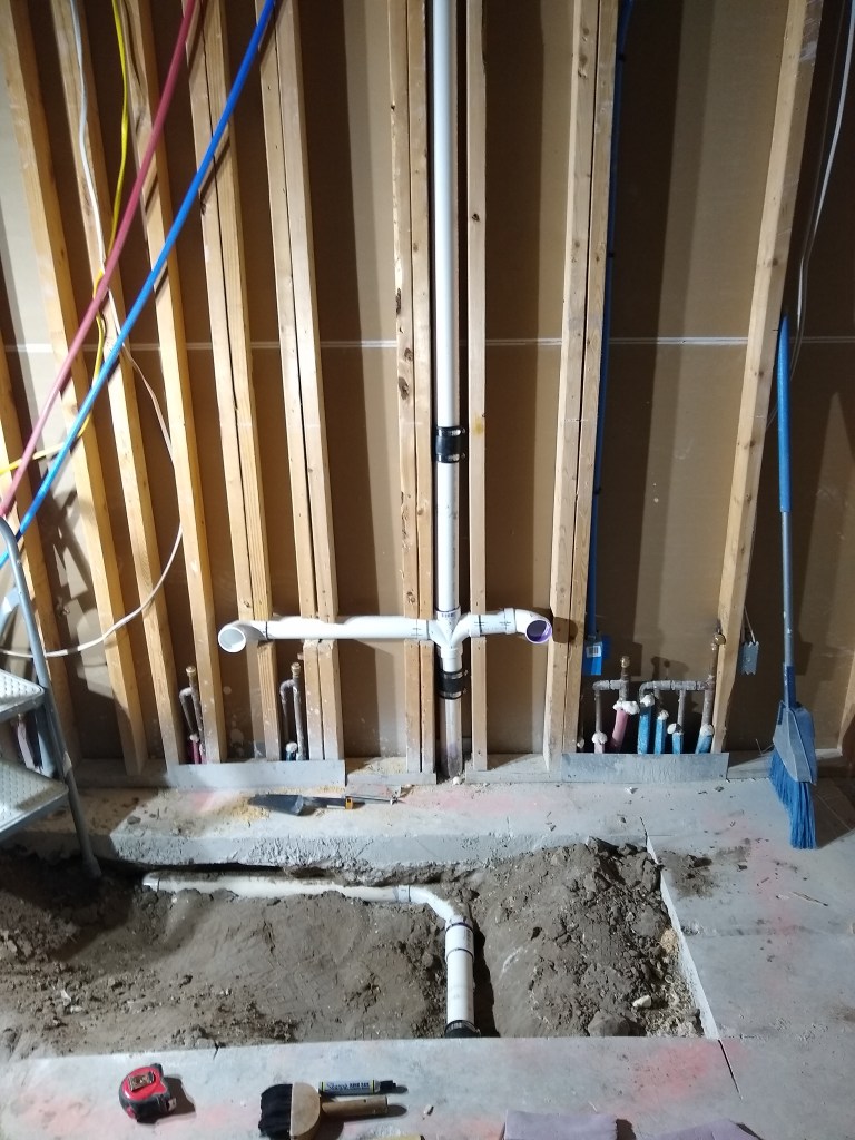
One more thing before we go. In the June/July post I talked about installing the hot water heater. At that time I had not yet had my work inspected. During this month I had the inspection done, but failed. I needed to add a pressure relief valve between the main supply line and the hot water heater. I was under the impression the relief valve that came with the tank was sufficient, but the inspector informed me that it was for relieving pressure when the temperature was too great. The valve I needed was to relieve pressure when the water pressure from the city fluctuates. That is, at different times of day it can change. An adjustable pressure relief valve is needed to keep the pressure consistent. So I have since installed it, as shown below.
PRV Installed
PRV Closeup
As you can see, I tee-ed off the main cold water line (purple primer everywhere). The PRV has a dial at the top of it (left in the image above since the valve is installed on its side) that is used to adjust the pressure to what you want. If the pressure exceeds that, the excess will flow out the line going down and out of the garage.
This was just inspected, and I passed. So on to the guest bathroom.
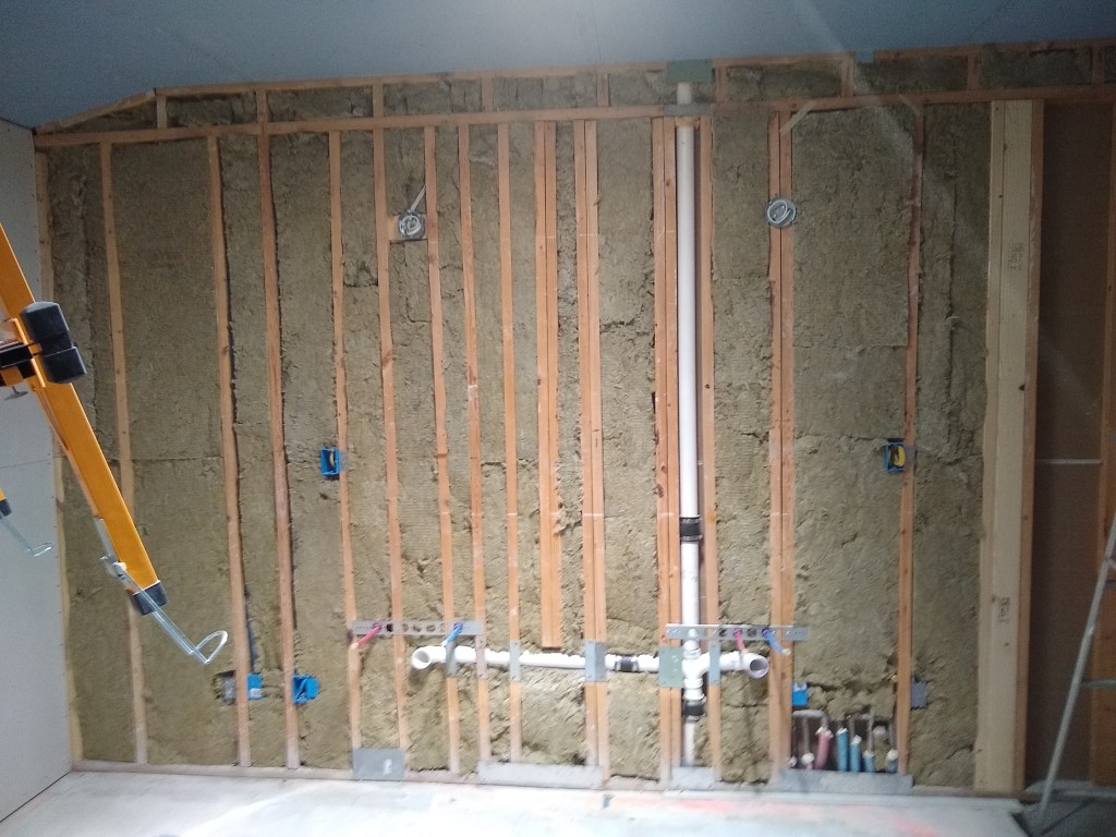
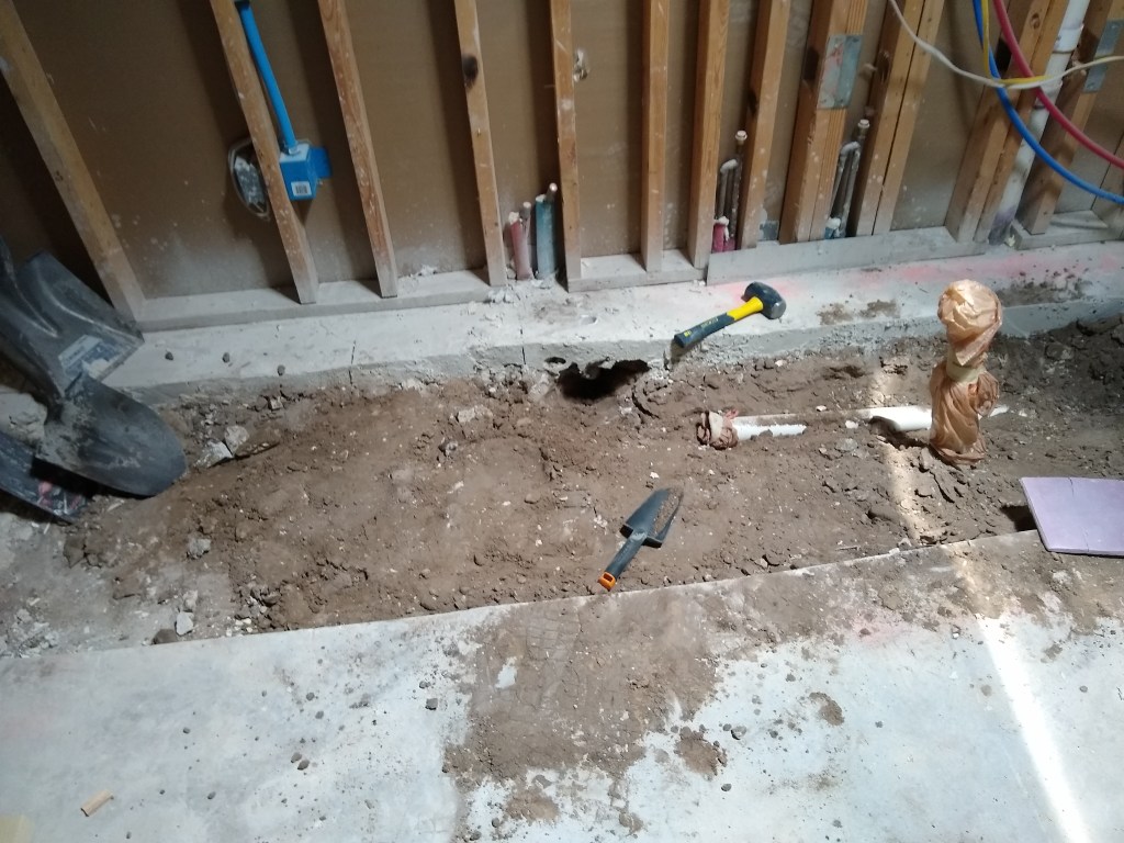
While waiting for the shower wall tiles and extra floor tiles to arrive, I decided it was a good time to hook up the hot water heater and install a utility sink in the garage. My original plan was to use the existing hot water heater, since it wasn’t that old. Here is the only shot of it.
Existing Hot Water Heater
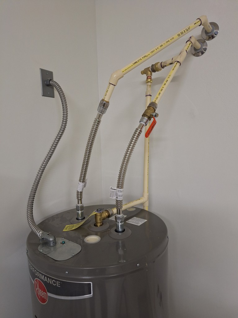
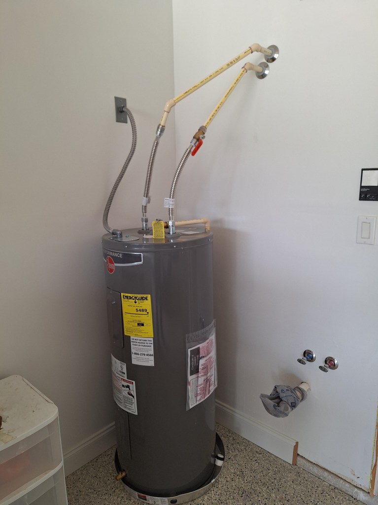
This was a 50 gallon hot water heater that was in place before I started this project, when I drained and disconnected it, with the intention of reusing it. Although it was only a few years in use, I removed the pressure relief valve that is located on the side of the tank to have a look at it and replace it (something one should do from time to time). I saw quite a bit of scale on it, which caused me to rethink whether it was a good idea to reuse the tank. I did not want to go through the trouble of hooking it up only to replace it not long after. So I purchased a new one. This time I got a 40 gallon tank, since that should be plenty for my needs and those of any guests I might have. Here it is installed.
40 Gallon Tank Installed
Rather than use 90 degree bends to feed the tank, I used 45 degree connectors for a straighter run. I think it looks a bit odd, but that’s okay with me. An inspection will reveal whether any changes are required. At this point it is working and I have hot water again.
Closeup of the Hookups
Pressure Relief Valve Hookup
In the image above, you can see that the pressure relief valve is connected to the existing pipe that takes the water outside the garage.
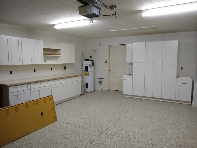
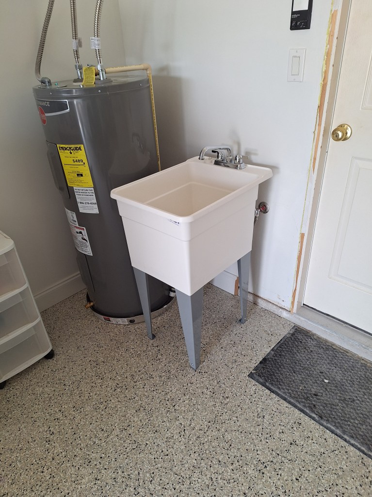
With that done, I installed a new utility sink beside it.
Utility Sink Installed
I had intended to reuse the utility sink that came with the house; the one I relocated to the guest bathroom. However, since it was my only source of water, I did not want to disconnect it without having an alternative, so I kept the existing one in place and bought a new one for the garage. I opted for a slightly smaller tub since I am limited in space between the hot water tank and the door (there is still trim to be added around the door). The existing utility sink is 20″ wide and this new one is 18″ wide.
Front View
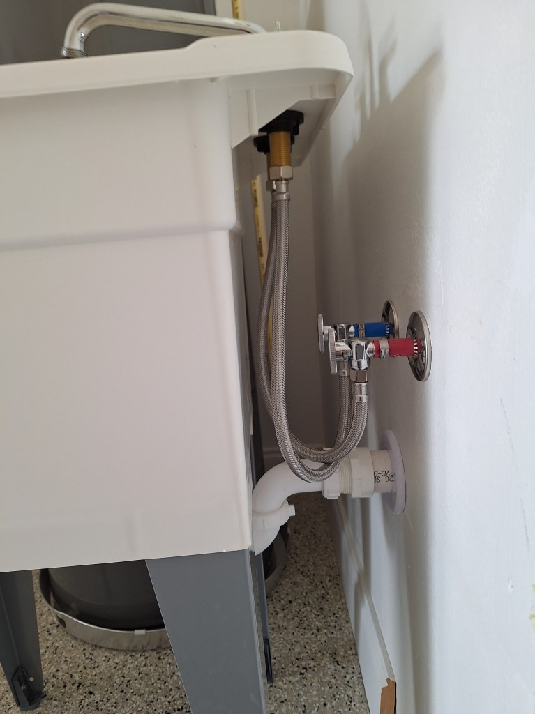
I think the smaller size was appropriate, as it tucks in nicely without looking too crowded. Here is a shot of the hookups.
Sink Hookups
Notice how the hot and cold lines cross each other. This was a funny little mistake I made when bringing those lines through the wall into the garage. On the other side of the wall they are oriented correctly (hot on the left, cold on the right). I didn’t realize at the time that it would be backward on the other side of the wall. No big deal, and I had a chuckle over it once I realized.
The sink has not yet been fastened to the floor. As with the hot water tank, this will need to pass inspection, which I haven’t arranged yet. I don’t want to secure it to the floor in case the inspector wants me to make changes. So I’ll have to be careful not to jostle it, which can damage the drain connections. In the meantime, it is nice to have hot water and an alternate wash basin to use.
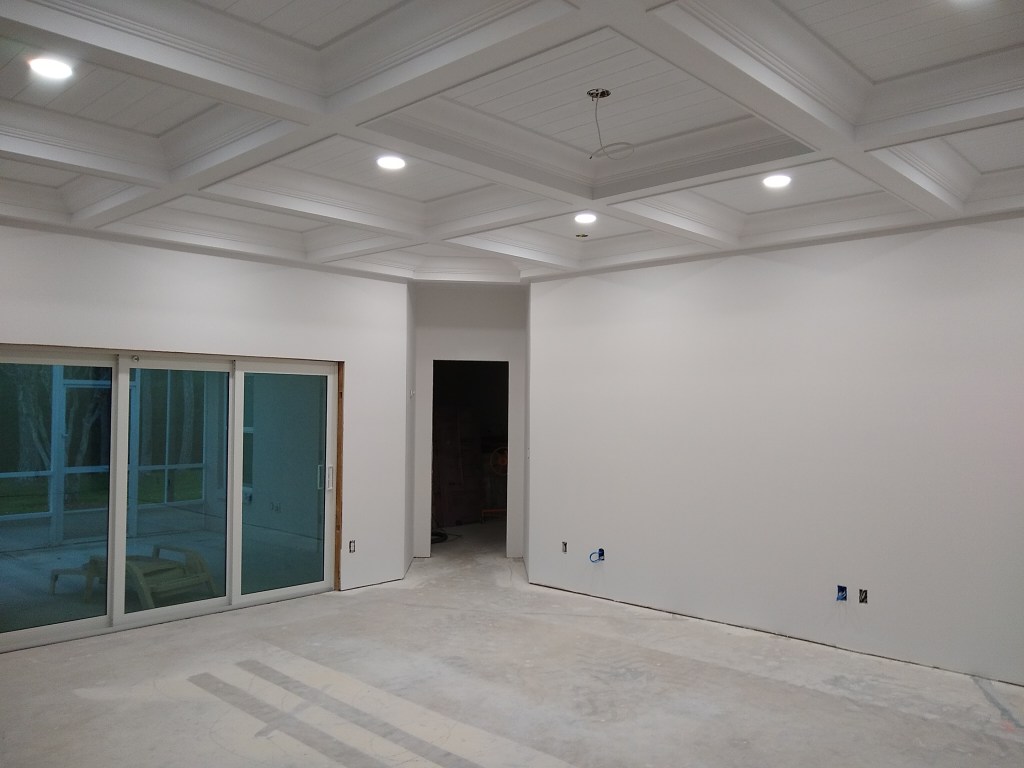
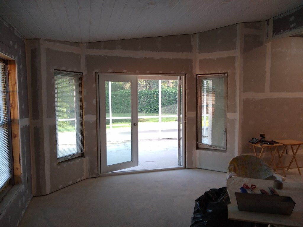
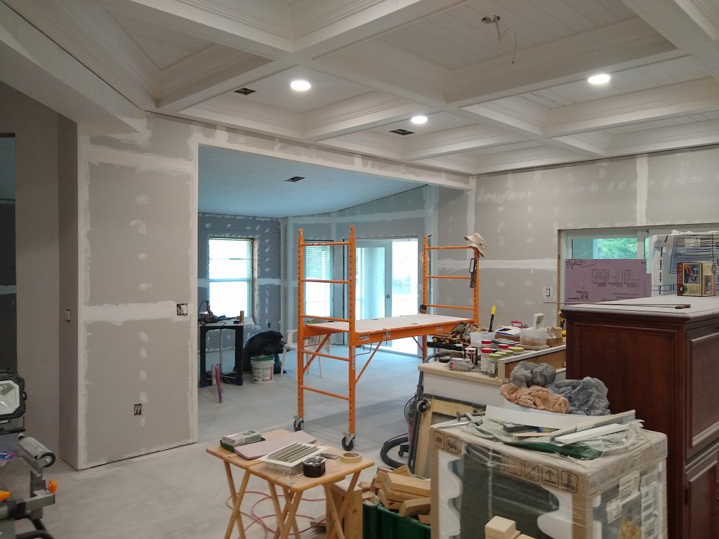
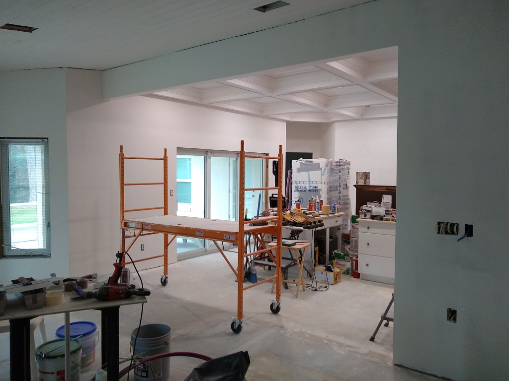
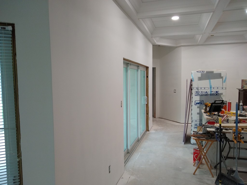
After this was completed, I contacted the place where I purchased my shower wall tiles to get an idea of when they would arrive. To my surprise, it was going to be at least another week, so change of plans. I decided to start painting the ceilings in the great room, foyer, and guest hallway.
These areas had some intricate details, so I decided to use a brush to paint them. When applying the primer, I used both a brush and small roller, but to get a consistent finish, I would use only a brush, which made it a lengthy process, especially since I applied two coats. I used a high quality latex paint with a matte finish – Behr Dynasty Ultra White.
My shower wall tiles arrived after I completed the painting of the ceilings, so I picked them up and set them aside. The master bathroom would have to wait. Having started the painting process in the great room, I decided to push on and paint the ceiling and walls in all adjoining spaces. This meant I would paint not only the great room, but also the dining room and kitchen.
The ceilings in all these spaces would be the same color (Ultra White). The walls in these areas would also be painted, but a slightly different shade of white. Originally I tried the color my designer recommended, which was a light gray – a color match of the Sherwin Williams Quick Silver. I applied it in the foyer to test it out. The next day I decided I did not like it. I expected it to be a light gray, but It had a hint of blue in it, which I did not want, Sorry, I didn’t take a picture of it. I really should have. Anyway, I considered making the walls the same color as the ceiling, but wanted some contrast, if only slight. So I opted for Behr’s White color. Not so white as Ultra White, but still white. I want the house to be bright. Here is a shot of the foyer so you can see the difference. It’s subtle, but present.
Foyer – Ceiling and Wall color contrast.
I really like this color for the walls. It just feels right.
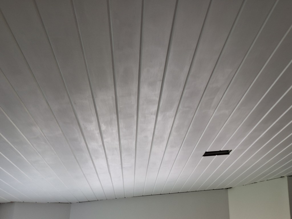
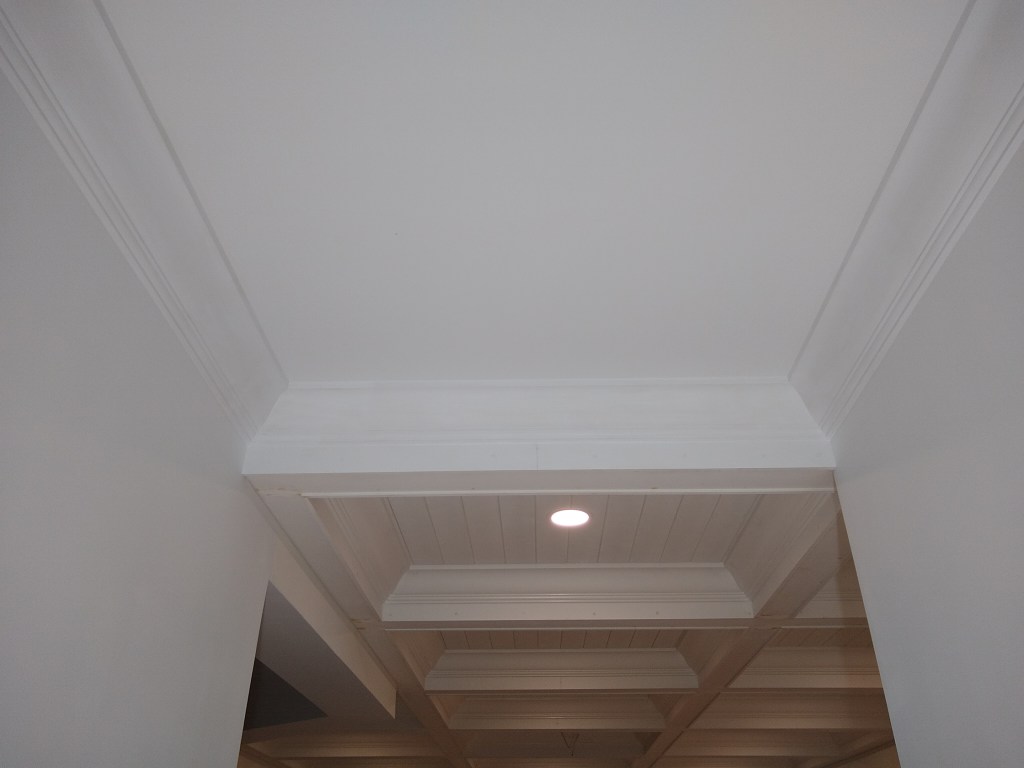
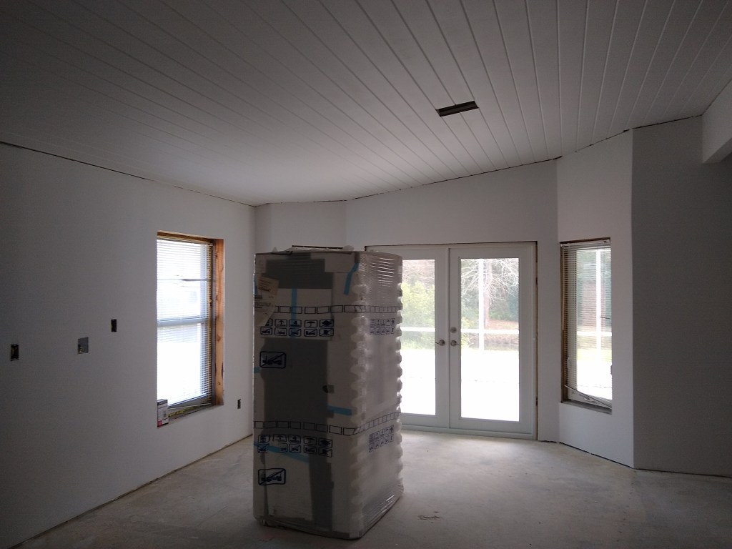
In the kitchen I started with the ceiling (as one should). Since it is a tongue and groove ceiling, I used a brush to paint the entire ceiling. I wanted to make sure the paint was applied to all nooks and crannies. Consequently, this took a long time to apply and was not fun. I applied two coats, as usual. However, after the second coat I was not pleased with the results. You could see a lot of “roping” (i.e., brush strokes). I thought the paint would level out, but it didn’t. Here’s what I was left with after all that work.
Kitchen Ceiling – Roping after brushing on Paint.
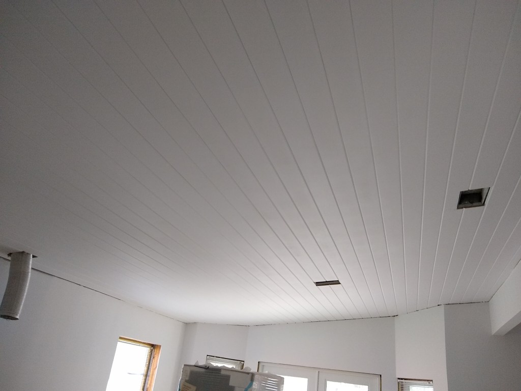
This is all well and good if you’re going for the hand painted look, but I wanted a more polished look. So I decided to applied a third coat, but this time using a roller. Having used the brush to ensure all the seems were properly painted, all I really needed to do was smooth out the flat areas, so I figured a roller would do the trick. It did! And here’s the result.
Kitchen Ceiling – After Rolling. Much better!
That’s what I was looking for, and I was very pleased with the result. Note that I will add crown molding between the ceiling and walls, but only after the kitchen cabinets are in. They will dictate where the crown ends, so the crown molding must wait. Because I need the cabinets to be in before installing the crown, it also means the floors will be in (the cabinets will sit on top of the wood flooring), so when I come to painting the crown, drop cloths will be needed to protect them. Something I don’t have to worry about at this stage. It’s nice to be able to paint without concern about dripping paint on the floor.
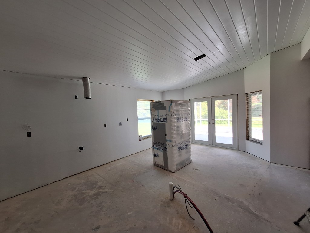
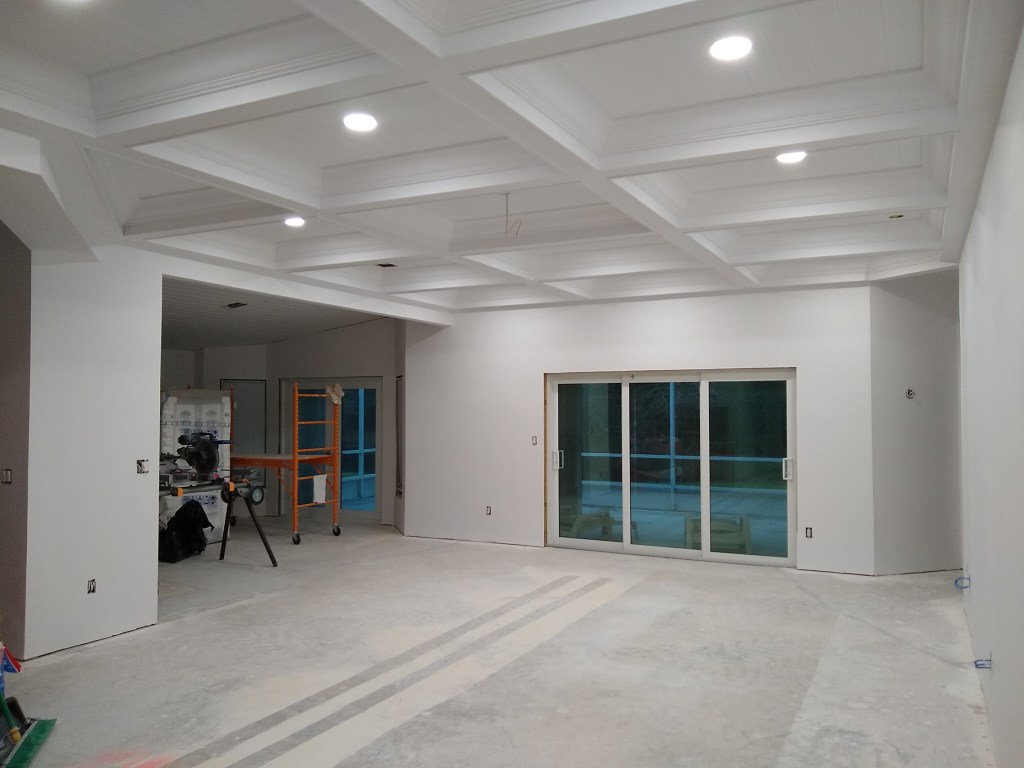
Here are a couple more views of the kitchen where both the walls and ceiling are painted.
Kitchen – Southern View.
Kitchen – Northern View.
Not that it is noticeable in the pics above, but I did not paint the walls where the cabinets will go (from where the vent is hanging down and to the left of it), for obvious reasons. They were primed, but that’s all. It gives you an idea of how close the wall color I picked was to the color of the primer. There is a difference, but it is small.
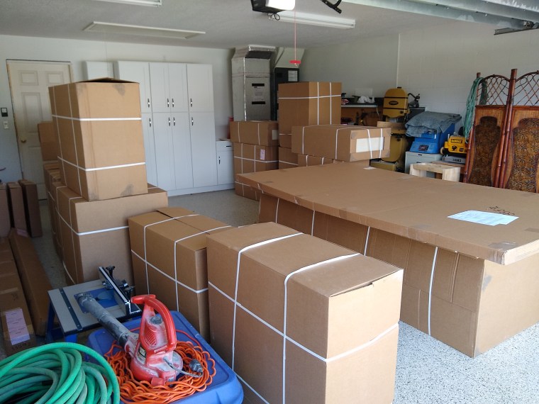
Also notice how, other than the refrigerator, I had to empty the kitchen in order to paint. That was not such a big deal because of the mobile bases I added at the beginning of the year (see the post from January). So I’m glad I took the time to do that. After the painting was done in the kitchen, I moved everything back in, freeing up space in the great room for the contents of the dining room, which was the next area to be painted. The dining room was where I stored all the kitchen cabinets. You can see them in the image above. They were moved one at a time into the great room. No mobile bases for them, so that was a bit of a chore.
Here are some shots of the dining room fully painted.
Dining Room – Ceiling and Walls Painted
Dining Room – Ceiling and Walls Painted
Dining Room – Ceiling and Walls Painted
In the last image above, you can see where I located the kitchen cabinets in the great room. You can also see in two of the images above that I have not yet installed a light fixture in the dining room. The wire hanging down is hooked up to the switch on the wall, so it’s ready to go, but having that light fixture in place is not really required before I move into the house. I haven’t decided on a fixture yet, so I’m inclined to put that off until I’ve moved in. By waiting until the piano is in position I’ll be able to raise the lid and see exactly how much room I have between it and the ceiling, which could impact my choice of fixture. However, with the piano in place directly under the fixture location, it will be in the way, making installation a bit tricky. Fortunately, I don’t have to make this call until closer to move-in time.
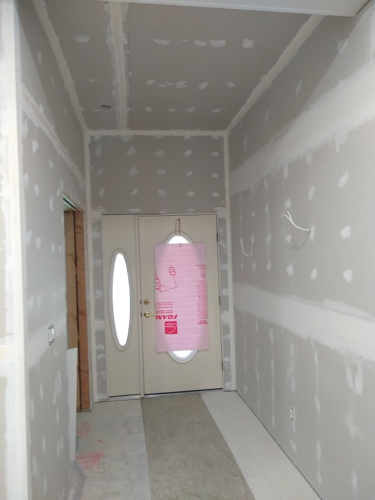
Below are some images of the other areas I painted.
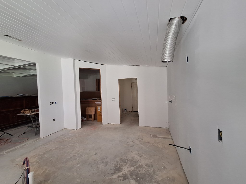
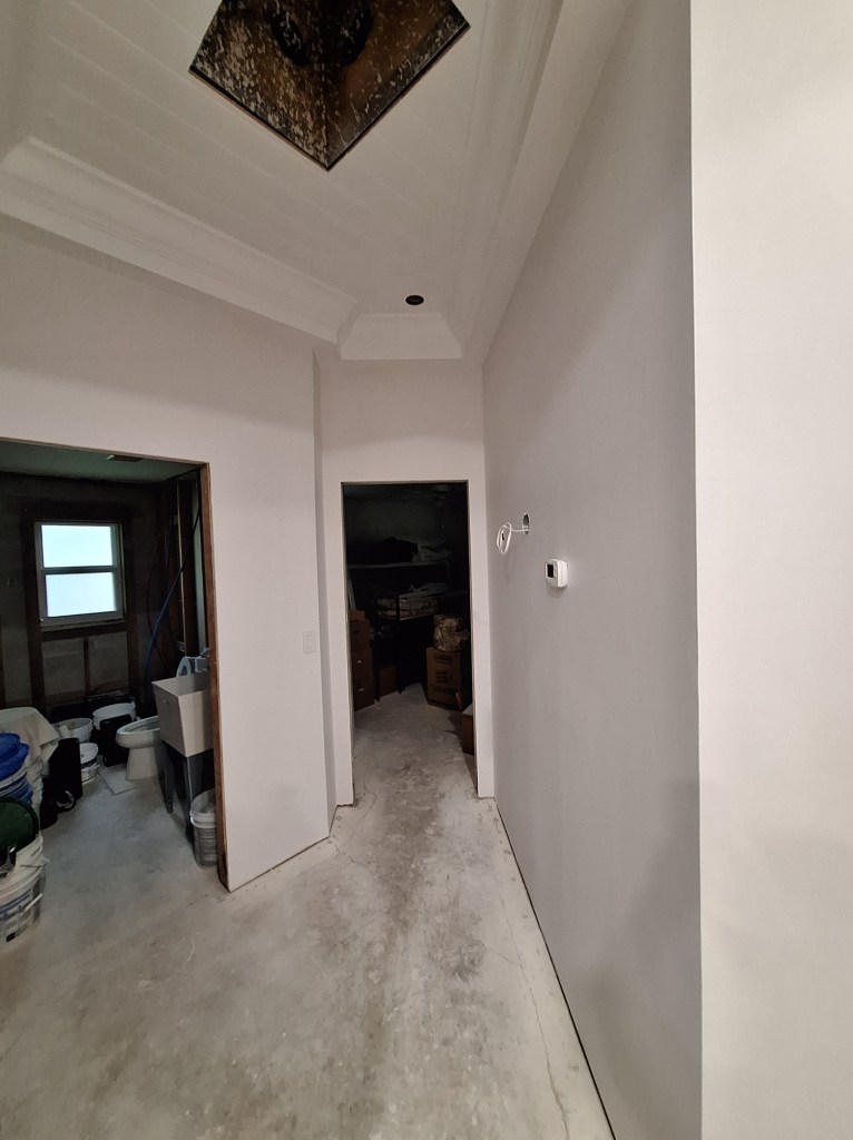
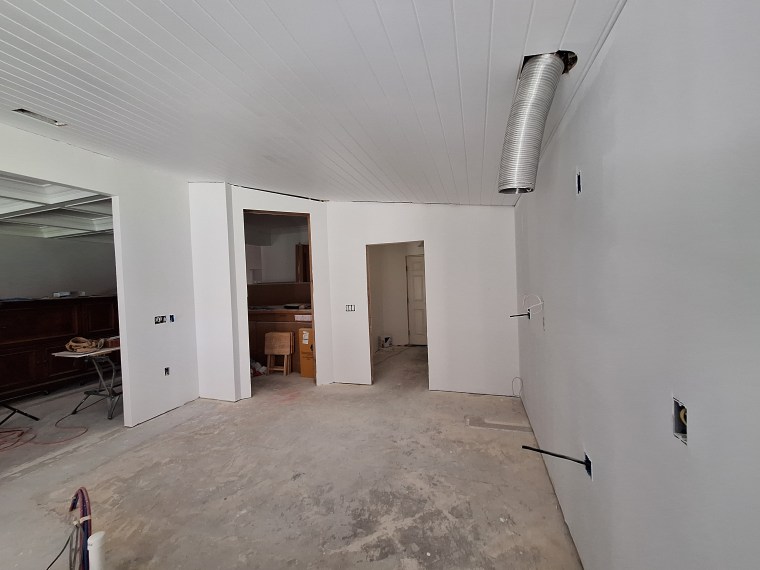
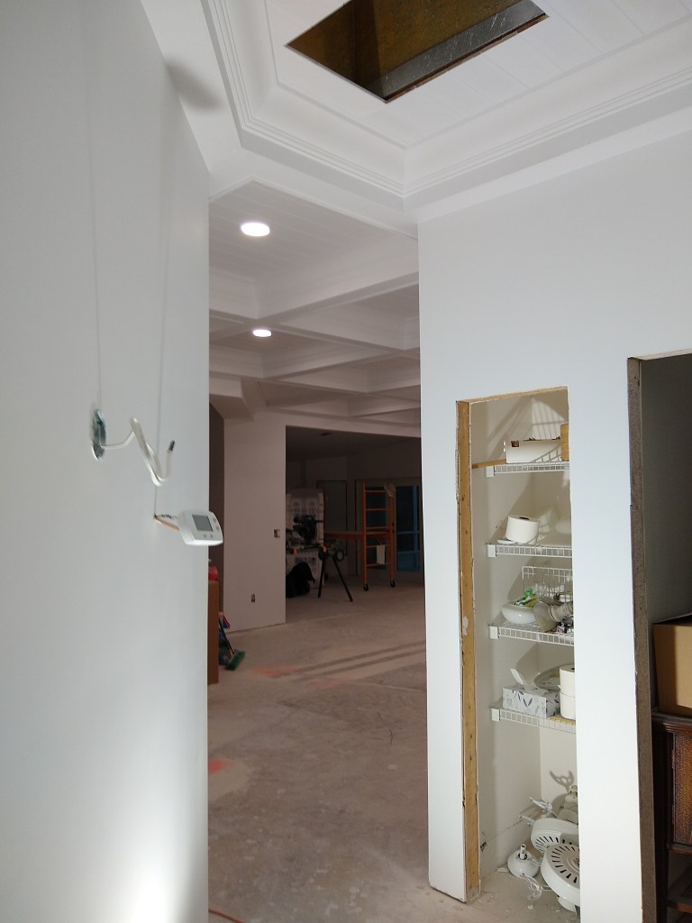
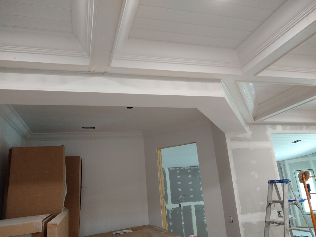
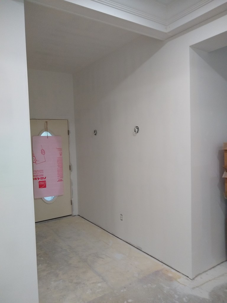
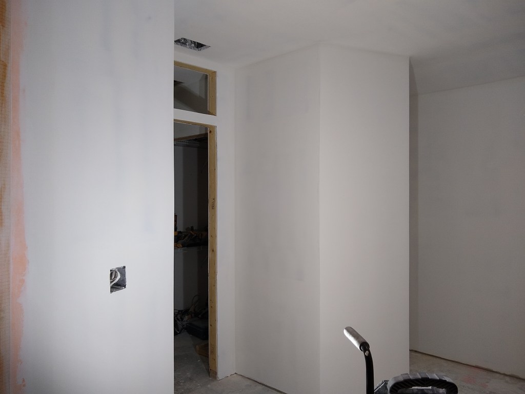
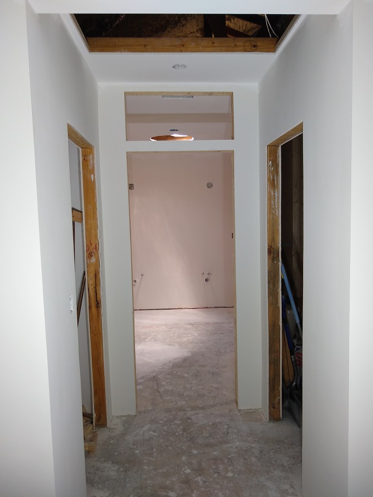
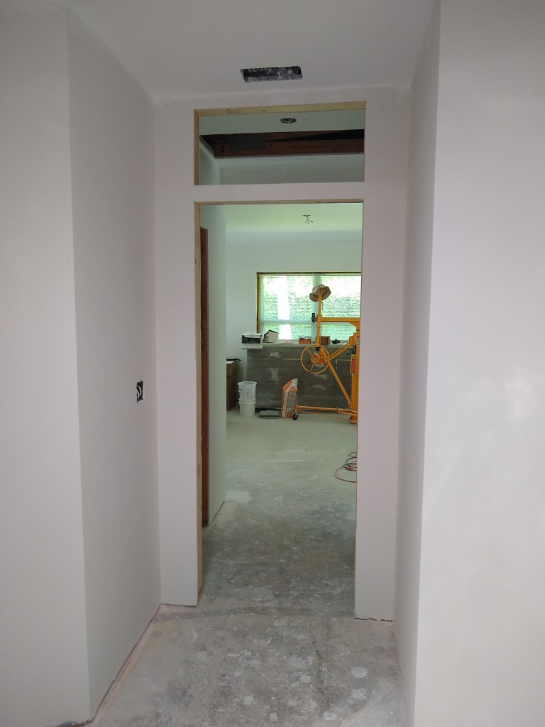
Foyer and Guest Hallway – Painted
Guest Hallway – Painted
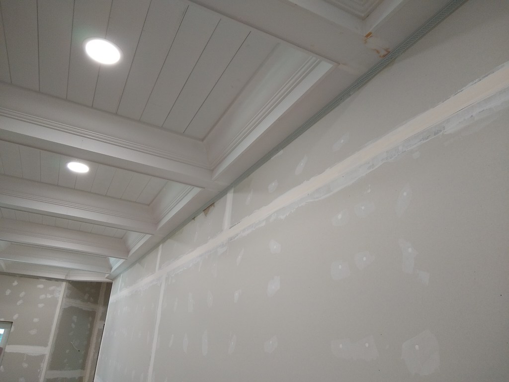
Within the guest hallway you can see that the plenum on the ceiling does not have a grate yet. That is because I reduced the size of that opening to accommodate the full width of a tongue and groove board. Therefore, the original grate no longer fits. If I’m unable to find a grate to fit the space, I’ll make one myself. Either way, this is not a priority for me at the moment.
As with the dining room, I’m in no hurry to install wall sconces, so the guest hallway and foyer will remain without them until I feel inclined. I can move in without these in place, so they remain a low priority.
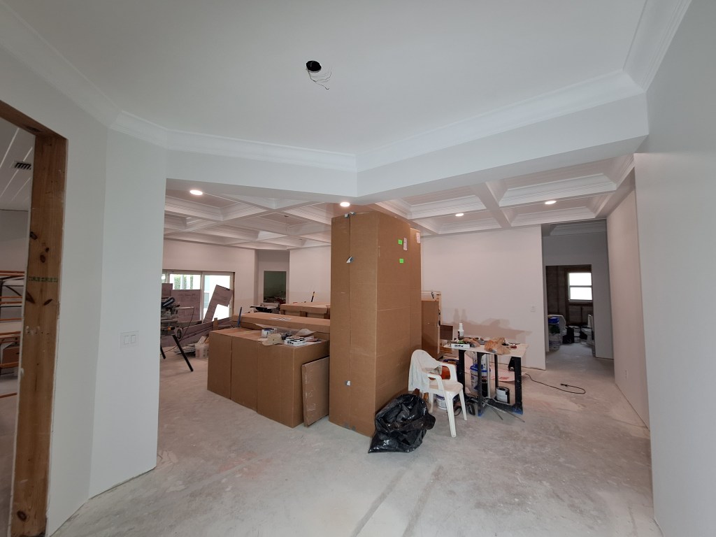
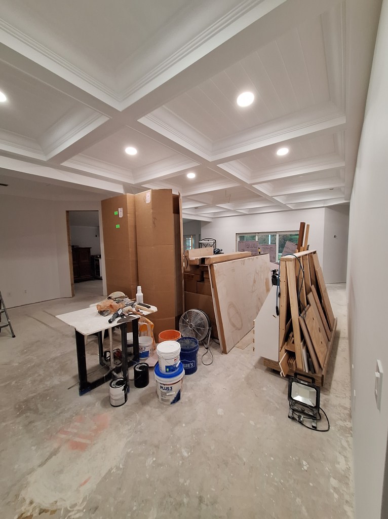
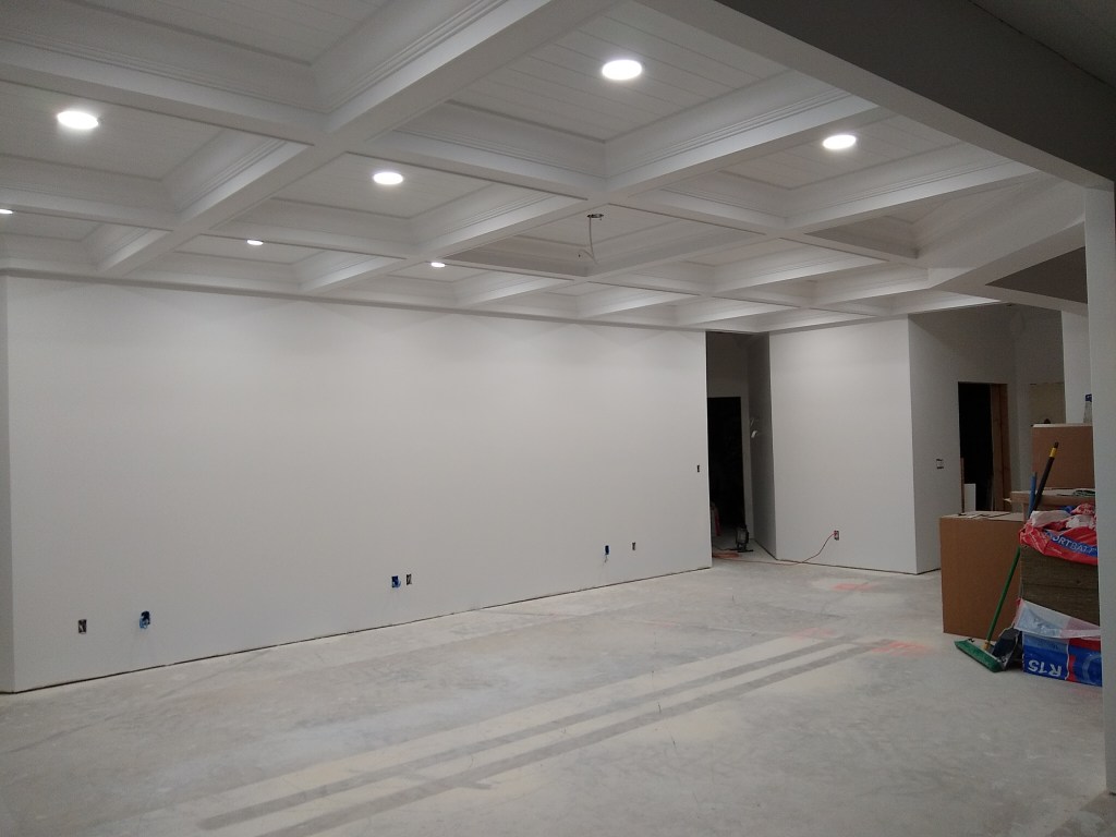
Great Room Painted – View from Guest Hallway
The above image of the great room is obscured by the contents I’ve left in the middle of the room. I will probably leave the cabinets and other bits and pieces right where they are until it’s time to put down the flooring. I thought I might move the cabinets back into the dining room, but I see no benefit to that at the moment. I’ll move them only when necessary.
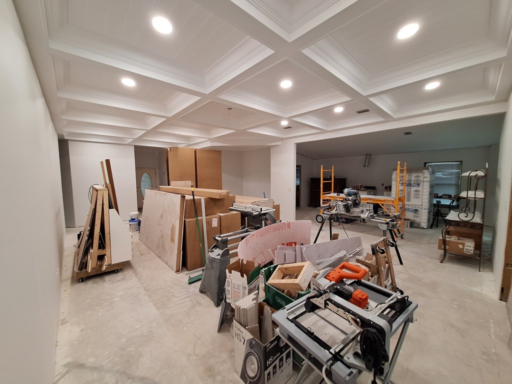
Great Room Painted – View from Entrance to Master Bedroom
From this view, you can see how much stuff occupies the great room. The mobile wood storage cart on the left will be moved into the garage, as will the various tools, but not until I no longer need them to be handy.
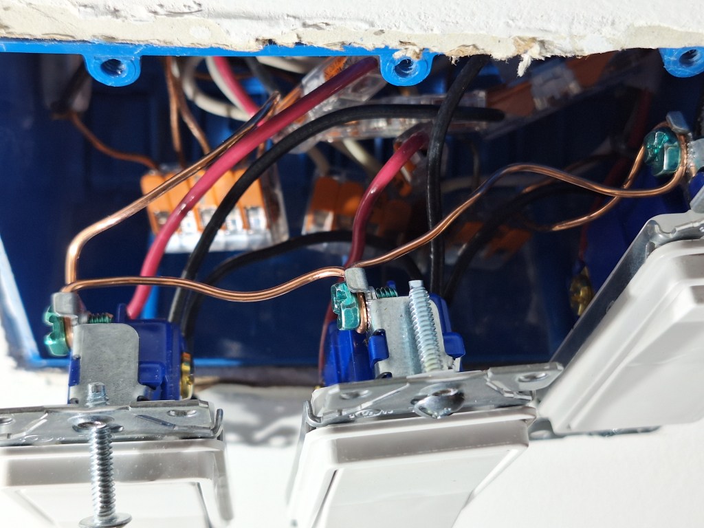
I installed the switches, electrical outlets, and the face plates for the Ethernet boxes in the various rooms only after all the painting was done in these areas. While installing the switches in the kitchen, I ran into some issues. The kitchen has two 3-gang boxes to control the ceiling lights, under counter lights, and kick plate lights. Each 3-gang box has three 3-way switches, so these lights can be turned on and off from either location. You can see them in the image of the kitchen (Northern View) above. Here it is again for your convenience.
Kitchen – Northern View
On the wall near the laundry room you can see that there are three switches installed (with no face plate). On the wall near the great room you can see the 3-gang box with no switches installed; just wires exposed. When I started hooking up the switches in these boxes, I began with the box near the laundry room. I pulled out the existing switches in the 3-gang box (what you can see above) and discovered that the wires within that box were very short. Also, the box itself was not very well supported. So I had some work to do to put in new switches and it was going to be tricky getting the switches to align. But what bothered me most was why it was in this condition.
That wall had been completely pulled apart and a new 3-gang box installed, all done by me. Not only that, but the three switches were also installed. So the question I had for myself was, why did I do that? Those three switches weren’t controlling anything, so why did I install them? They would only get in the way (as they did) when it came time to putting up and finishing the drywall. Fortunately I have a BLOG, so I went back and looked for the post when I did that work and found it in the post of March 2021. During that time I had not done any drywall, so I didn’t understand the benefit to keeping the boxes free of switches and well aligned and secured. I also was trying to figure out the wiring for these switches, so I wanted to install them and verify they worked, thinking it wouldn’t be long before I’d be installing the kitchen cabinets. Of course, after all that was done, and many moons later, I reconfigured the kitchen, resulting in my having to undo the electrical work on the wall by the great room. However, during that time, I did not touch the electrical on the wall by the laundry room and just forgot about the state it was in.
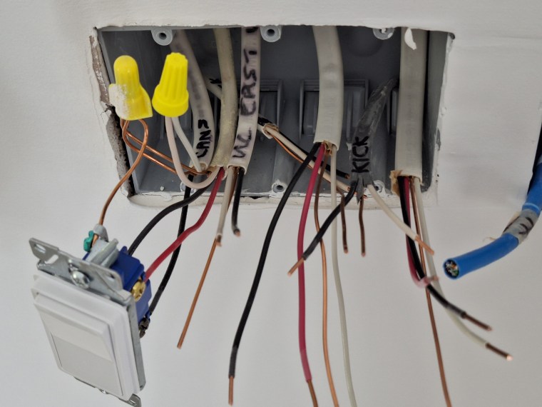
In that time, I’d done a lot of drywall work and therefore gained an understanding of the importance of securing the electrical boxes properly and keeping the wiring out of the way. So when I finally turned my attention to the wiring of these two boxes in the kitchen, I was most surprised by how short the wires were inside the box by the laundry room. Installing new switches was going to be very tricky because I had almost no length to work with. What I think happened was that I was trying to minimize the length of wire to reduce the amount of crowding within the box. With three switches in a single box, plus the wires heading out to the lights, it can get pretty congested. That was a mistake. So in order to fix it, I had to splice in some extra wire to give me the length I needed to install new switches without having to resort to wiring gymnastics.
3-gang Box on near Laundry Room
Although it is not clear in the image above, you can see plastic connectors with orange tabs. These are call WAGO connectors. They come in different sizes, allowing one to connect multiple wires together easily. They also have a nice “inline” connector, shown below.
WAGO Inline Connector
This connector makes it easy to extend a wire with minimal space impact. If you look closely in the image of the 3-gang box above, I have used several of these in the back of the box to splice in new wires to give me the length I needed to add the new switches with far less difficulty.
Here is an image of the other 3-gang box. The one on the wall near the great room.
3-gang Box near Great Room
This is how it’s suppose to be. Plenty of wire for me to work with. In this image you see that I have hooked up the 3-way switch for the overhead lights to make sure this switch works in concert with the one on the other wall to control the overhead lights. I then did the same with the other switches. Note that I swapped out the yellow wire nuts you see above with WAGO connectors when putting the other switches in. It made it much easier.
What all this shows, is that nothing beats experience; something I am gaining with every new task. My next task is certainly new; tiling the shower wall in the master bathroom. With the painting of the main areas of the house complete, I’ll be returning to the master bathroom to pick up from where I left off. That will be the subject of the next post.
Returning my attention to the master bathroom, the objective was to make it a functioning bathroom. This did not mean it would be fully finished; only finished enough that I could use it if I was living in the house. So I did not intend to go so far as have the baseboard done and entrance door installed.
I began by painting the previously primed walls. I used the paint recommended by my designer and was very happy with the choice. It was a color match of Sherwin Williams Alabaster. I got it at Home Depot under Behr Dynasty with a satin finish.
Painting Complete – from Entrance.
Painting Complete – from Shower.
Painting Complete – from NW Corner (a bit fuzzy – sorry).
Painting Complete – Toilet Alcove.
You’ll also notice from the pictures above that I installed the outlets, switches, lights, fans (toilet and shower), and A/C grates. All are new, except the light in the toilet alcove and the A/C grates. They just needed a bit of cleaning. I thought the original light fixture I installed in the toilet alcove was perfectly fine for that location.
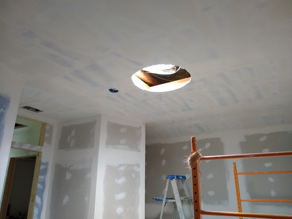
Another thing I did was reinstall the sun tunnel. This took a bit of work. In an older post I mentioned that I wanted to relocate the sun tunnel to be centered on the entrance hall. After making the required changes for that, I just left it dangling, to deal with another day. To be perfectly honest, I was not looking forward to putting it back together in the new location. In the new location, the tunnel part only just reached, leaving some gaps in the reflective foil part on the inside of the tunnel. So I was going to have to come up with a way to patch it. Furthermore, the face-place (the part that surrounds the diffuser) was a bit yellowed, so that would have to be addressed. After scuffing up the surface of the face-plate with some sand paper to prepare it for primer, I gave it two coats, followed by two coats of clear satin. I was very pleased the result. It looked brand new. In between coats, I worked on the diffuser, cleaning it up.
With the faceplate dry, I installed it. That went better than expected. A little widening of the existing opening and it went into place nicely. I then pulled the tunnel part into it and fastened it in place. I used heavy aluminum foil and some foil tape to patch the gaps, which worked like a charm. You’d never know it was patched. I then put the diffuser in place and it looked just great – as if it had always been there. Sadly, I didn’t take any pictures of the process. I was too focused on solving the problem to think about documenting it, so you’ll have to settle for this description and the final result you see in the pictures above.
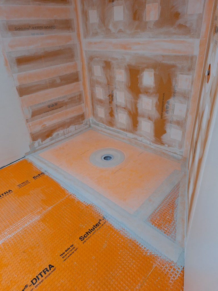
I originally thought I’d set the shower pan next, but after some thought I decided it would be better to first put down the underlayment for the tile flooring in the main part of the bathroom. The plan was to create a curbless shower, which meant that the shower pan would have to align with the surface of the main flooring. By putting the underlayment material down first, I would have an actual target to shoot for rather than a theoretical target where I’d have to calculate the height of the shower pan including the additional height of the underlayment and thickness of the thin-set mortar. So I started on that.
The underlayment material is a product by the company Schluter, and is called DITRA. It is a polyethylene membrane with a fleece on the bottom. It serves to separate the tile that will go on top from the concrete slab beneath. By separating the tile from the slab in this way, you reduce the likelihood of the tile cracking as a result of minor slab movement. The DITRA membrane is installed directly to the slab using thin-set mortar.
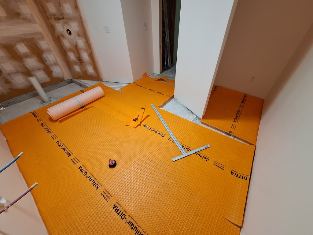
Before mixing up the mortar, I unrolled sections of DITRA and used scissors to cut it to fit the floor.
DITRA Installation – Cutting and Fitting.
I cut two large sections first before tackling the more fiddly bits. Here are a couple of shots after the dry fit was complete.
DITRA Installation – Dry Fit Complete.
DITRA Installation – Dry Fit in Alcove.
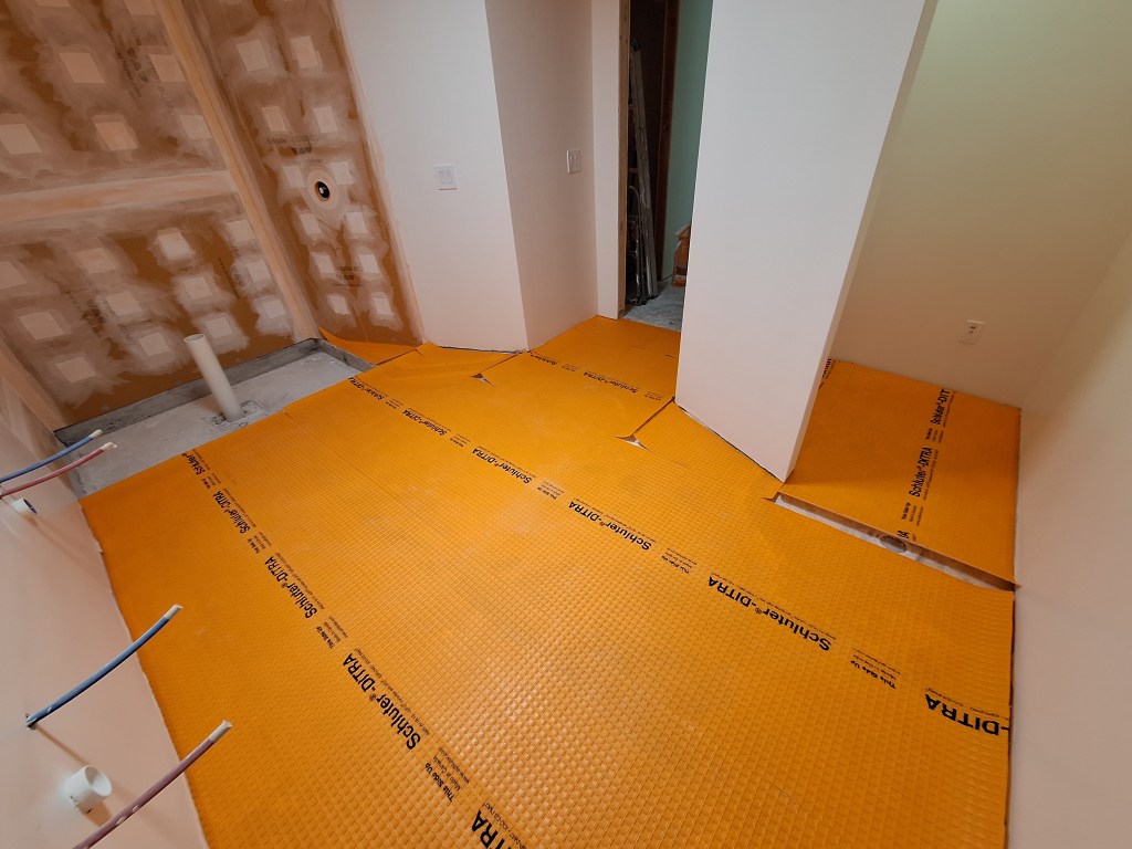
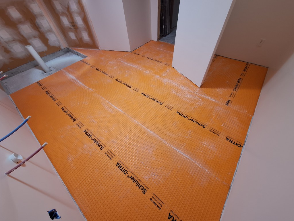
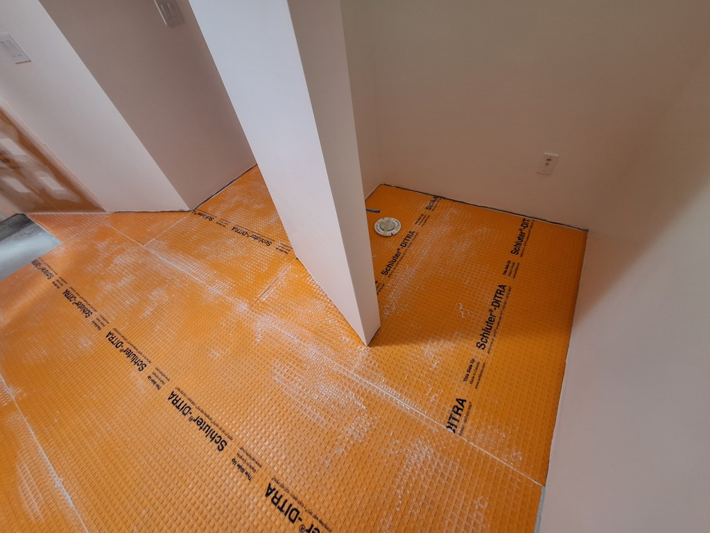
With that done, I mixed up the thin-set and adhered it to the floor. Here are the results.
DITRA Installation – Complete
DITRA Installation – Complete
DITRA Installation – Complete
With that done, I turned my attention to the shower pan. The shower area is recessed about 4-1/2″ below the bathroom floor. I will be using a Schluter preformed shower pan that provides a consistent slope from the edge to the drain. The preformed shower pan is 1-1/4″ thick and is to be placed on top of a flat surface. This means that I must raise the recessed shower area by about 3-1/4″ so that when the preformed pan is placed on top of it, it aligns with the bathroom floor. To do that I used dry-pack mortar, which is a 4:1 mix of sand to cement. It is mixed with just enough water to make it like wet sand you would play with at the beach when building a sand castle.
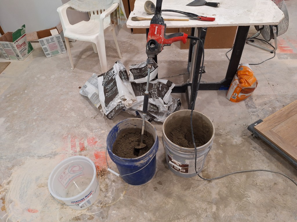
I mixed the dry-pack in buckets and dumped them into the shower area one at a time.
Dry-pack Mixing
I ended up using 13 55lb bags. When I started this, I was using a single bucket, but switched to using two buckets and dividing the contents of a single bag between them. The contents of the bag almost completely filled a single bucket, making the mixing precarious. It was difficult to avoid spilling some of it onto the floor. Also, that full bucket was really heavy. By using two buckets, I was able to mix the contents more aggressively and each bucket was easier to lift. I used a dolly to move the two buckets from where I did the mixing to the bathroom, so I only had to carry each bucket from the entrance of the bathroom to the dumping area. Still, at the end of the day, I was feeling it.
Dry-pack – Building up the Base.
After dumping the contents of the buckets, I used a small garden hand trowel and concrete float to spread it out. After 13 trips, I brought it up to this level.
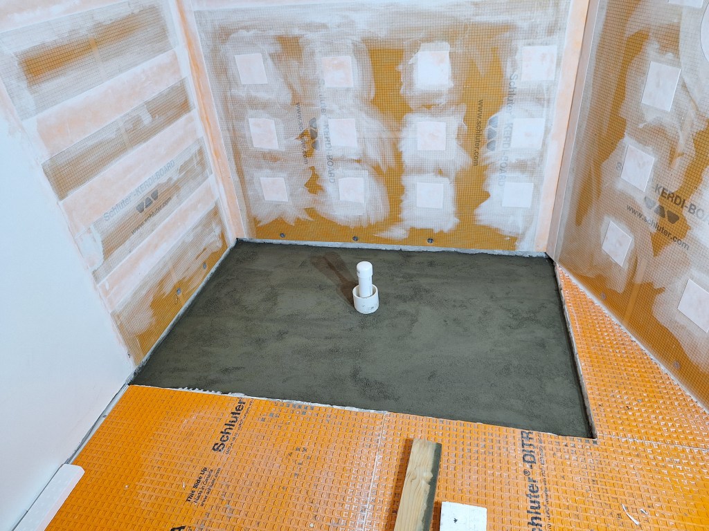
Dry-pack – Complete.
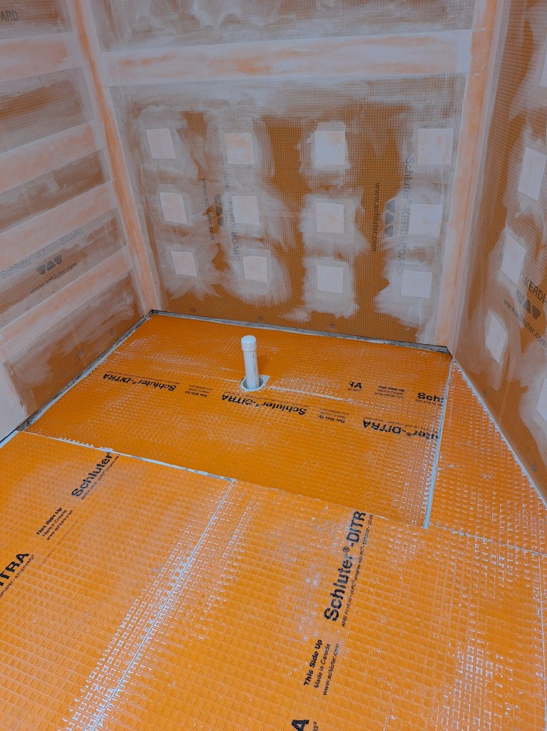
I used a 2×4 as a screed, a level (of course), and the concrete float to smooth it out. It is just shy of the desired height, but it is pretty flat. Once cured I thought I’d use a self leveling compound to bring it up just a bit more, but after thinking it over I decided not to do that. The bed was pretty flat and level and I only needed to bring it up a tiny bit, so I decided to use the left over DITRA I had to cover it. Also, note the 4″ collar I have around the drain, that proved to be a mistake, which I’ll discuss shortly.
DITRA over Mud Bed
The next day, after the thin-set used to set the DITRA membrane had cured, I placed the preformed shower pan in place just to see how it looked and lined up with the edges of the bathroom floor.
Shower Pan – Dry Fit
This is about as tight a fit as you want, so I was happy with that. It remains a bit lower than the bathroom floor, but better that than high. Also, I think I know how I’m going to transition from the floor tile to the shower floor tile, so having the shower pan a little lower should be okay.
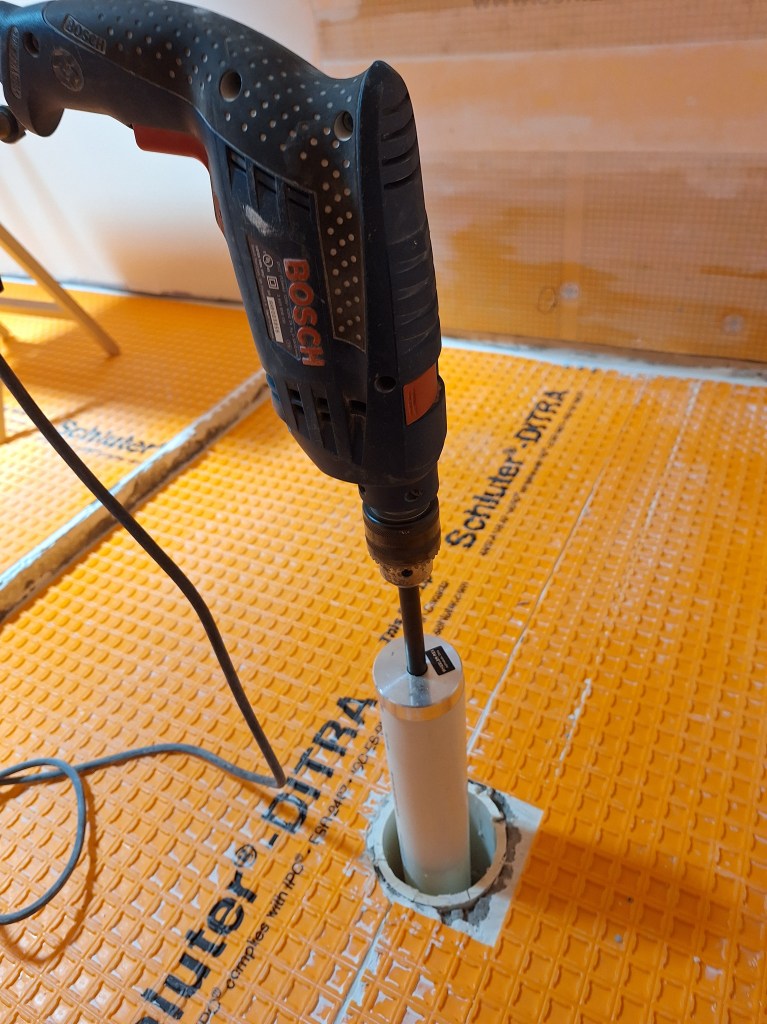
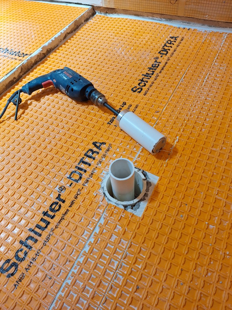
Back to the 4″ collar issue I mentioned. I made a silly mistake when I put that in place. Instead, I should have used 5″ PVC pipe as the collar. This is because the Schluter drain widens from the 2″ opening that connects to the drain pipe to just over 4″ near the drain opening. This means that it will not fit into the space I created around the drain pipe you see above. Fortunately, if I remove the 4″ collar, I should have just enough room to make it fit. The issue then became, how do I remove the collar. It is well secured within the dry pack mud bed. After some thought I realized that once I cut the drain pipe down to its final level, it will be below the collar by enough to allow me to use my inside pipe cutter to take off just enough of the collar to make room for the drain. So that was how I proceeded.
To cut the drain to the desired height, I purchased a new inside pipe cutter specifically for 2″ PVC. Unlike my current cutter, which is like a mini saw blade that you slowly move within the pipe, this one removes the section of pipe in one swift motion. More importantly though, it makes a straight cut, which is helpful when trying to ensure the drain is level. Before cutting the drain down to final height, I tried it out by first removing a section to make sure it worked as expected.
Test Cut to try out my new Inside Pipe Cutter
Test Cut Successful – Cutter works well.
After that I did it again, but this time to the final height, which was a couple of inches below the floor. The entire drain installation was dicey and had my full attention, consequently I forgot to take pictures of the intermediate stages. So my description will have to suffice.
After cutting the drain down to final height, I cut away the outer collar to about the same height as the drain pipe. This worked, but was not as simple as that. The drain pipe was not perfectly centered in the middle of the collar. Because I was not expecting it to be a tight fit, I didn’t give that much thought when I put in the mud bed. Although cutting away the collar provided most of the room I needed, one side was still too tight, so I had to grind away at the hardened mud to open it up a bit. This was very time consuming and frustrating. I managed to get the drain level, but it’s not perfect. I’m sure it will be fine, but this is why experience is so important. It shouldn’t have been this difficult. I’ll do better next time. Here is the drain after it was glued into place.
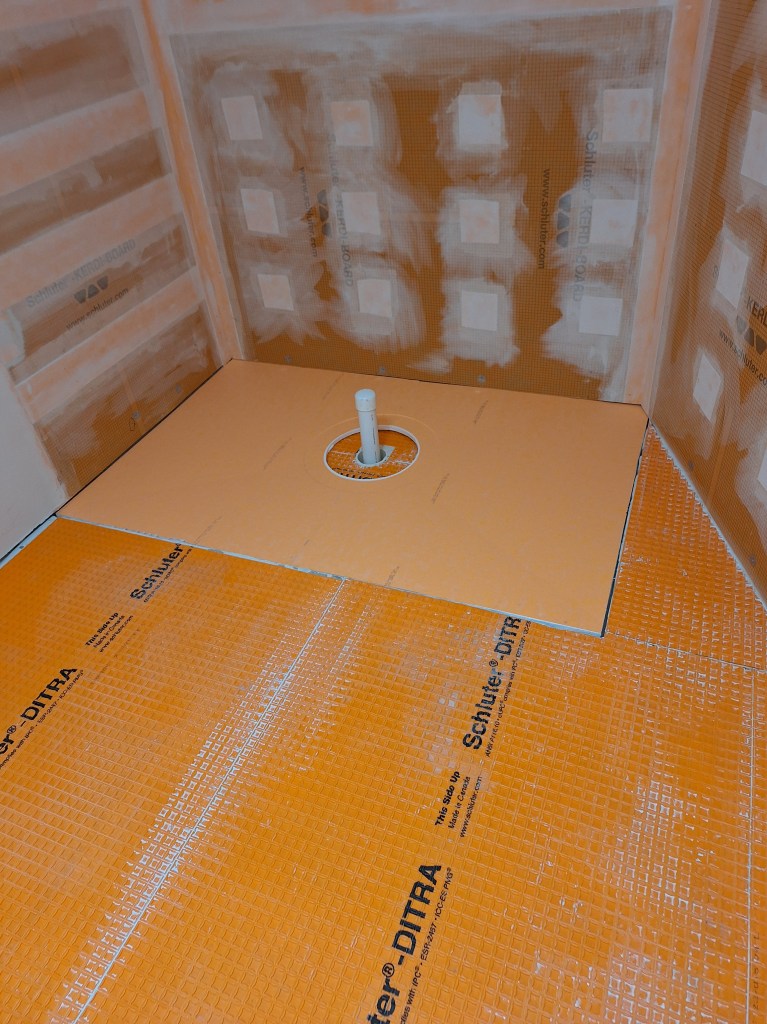
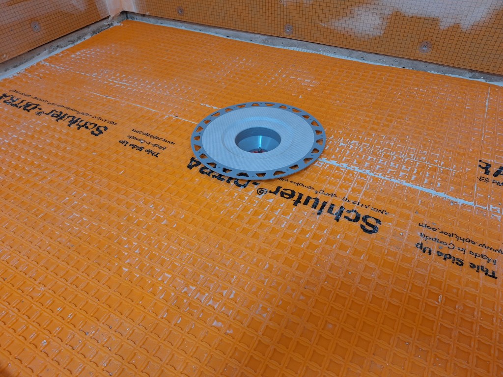
Drain Installed
The drain flange is supported by a Styrofoam ring that is placed under the flange and packed with thin-set.
Drain Secured
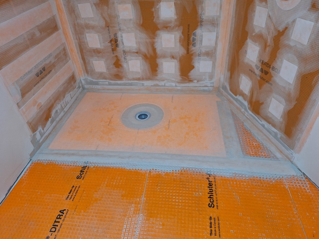
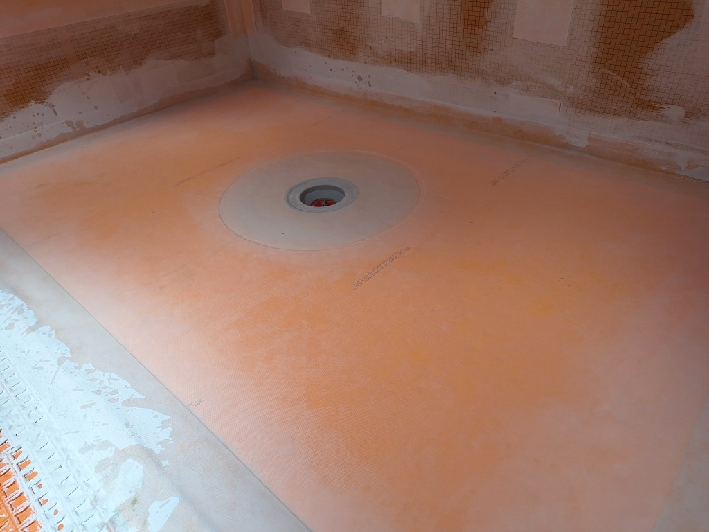
This was left to cure overnight. To complete the waterproofing, I put down the preformed pan and sealed all remaining gaps and seems using Kerdi Band.
Waterproofing Complete
Waterproofing Complete
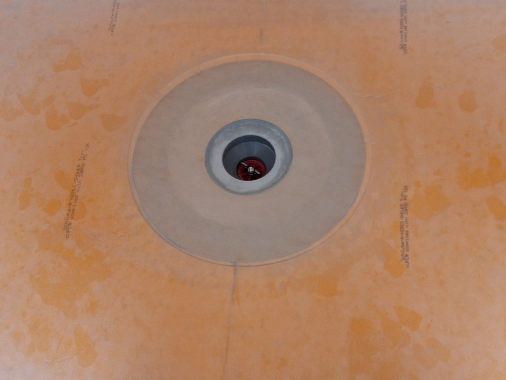
The drain flange is completely surrounded by the preformed pan, but the interface between it and the pan only becomes water tight once the donut shaped Kerdi membrane is fixed in place using thin-set.
Closeup of Drain with Kerdi Membrane
Once all the thin-set is cured, the shower pan was filled with water to make sure there are no leaks. You can see the red plug in the drain that will be used for that. The pan was filled as high as it could be without water flowing onto the bathroom floor, as shown below. Although hard to see, there is water in the pan.
Water Test
It was left for 24 hours and the water level checked to make sure it remains the same. I scheduled an inspection and it was approved.
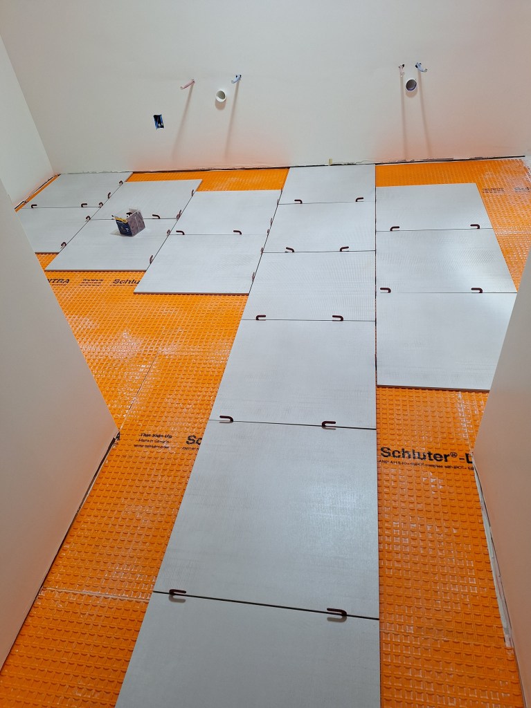
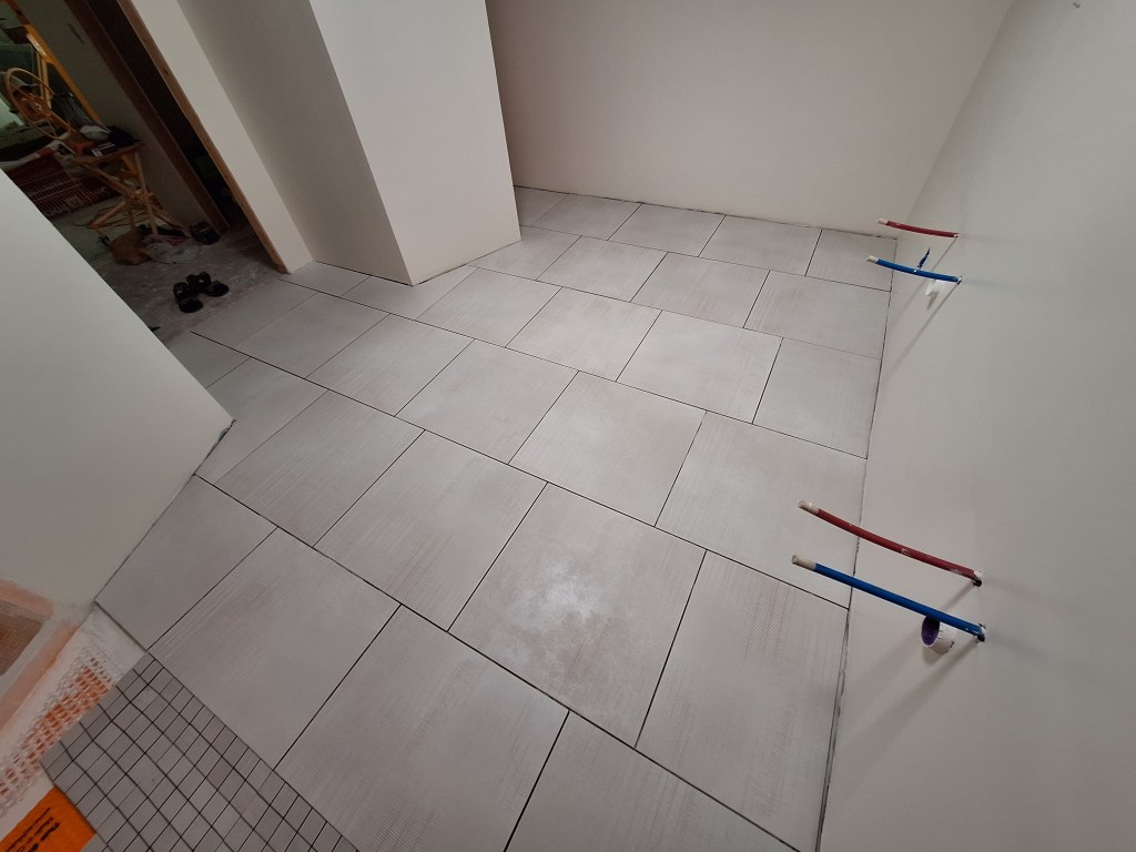
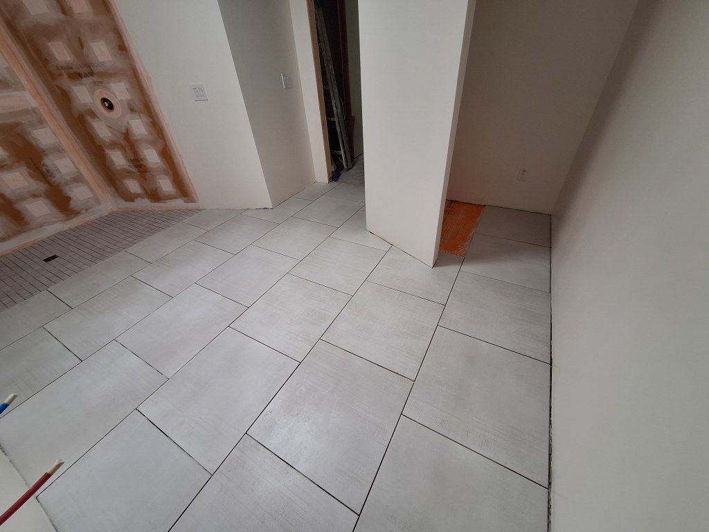
With the shower waterproofed, it was time to start putting down the floor tile in the main bathroom area. Before doing this, a lot of thought needed to go into how to lay it out. I used SketchUp to try several approaches. The first attempt was to simply lay them out right beside each other, as you see below. I thought it looked pretty good, so it remained a contender.
Simple Grid
In the first try I made no attempt to clean up the layout to match the floor plan, which is why there are tiles extending outside it. In my next few attempts I played around with shifting the columns. I tried a 50% offset (not shown), followed by a 1/3 offset, shown below.
1/3rd Offset, Stepping Up to the Left
In this layout, I have a full tile at the entrance and the tiles are offset by 1/3rd with a stair step pattern from right to left. I didn’t go with this because it introduced too many small tiles as you can see at the top and by the entrance.
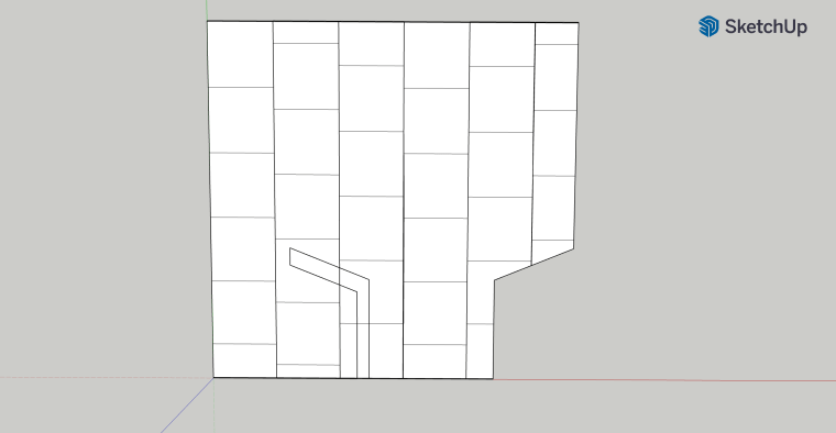
So I modified it slightly to have the stepping go up from the center row to the left and also go up from the center row to the right. Look closely and you’ll see what I mean.
1/3rd Offset, Stepping Up from Center Row on Both Sides
Also notice that I flipped the center row so that the full tile is now on top. This made better use of the tiles, reducing the number of small tiles. I played around with several other layouts, but liked this one, so I decided to dry fit it to make sure it worked as modeled. Unfortunately, it did not.
First Dry Fit Attempt
As you can see, this would lead to a 2″ sliver along the west (left) wall. That would not do. The reason for this discrepancy between the dry fit and the model was that the model assumed the tiles were 24″ square. In reality they were 23 3/16″ square, which over several columns produced the gap at the west wall. I thought about simply shifting the entire thing over to close the gap, but then I’d lose the nice centering of the center column on the entrance. So I went home and updated my model to account for the true tile size. I also accounted for the 1/8″ grout lines. This is shown below.
Final Layout
In the model shown above, I abandoned the step up pattern and instead used an alternating 1/3rd offset. This made even better use of the tiles, with virtually no small tiles. I also shifted it over a bit to close the gap, and to my surprise it didn’t look bad. So I decided to try dry fitting this layout.
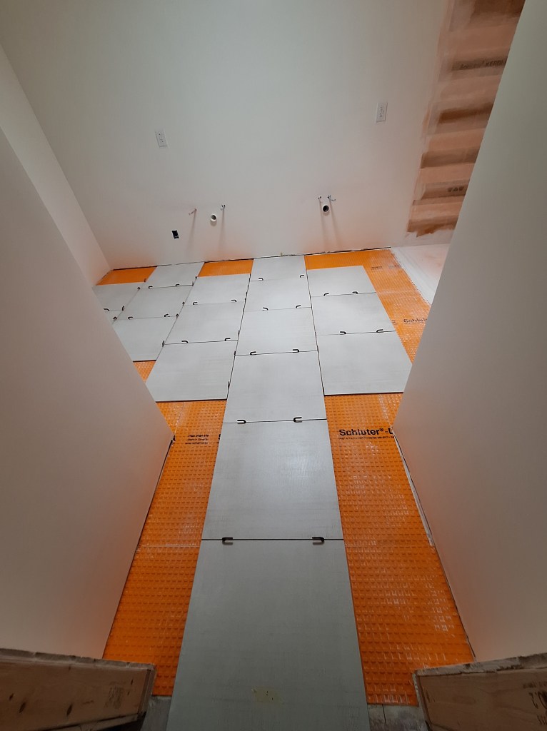
Final Dry Fit
Final Dry Fit
Yes, the center row is not perfectly centered on the entrance the way I wanted, but it is pretty darn close, and perfectly acceptable as far as I am concerned. There will be a door on the left side as you enter, so this will make it even less of an issue. Laying out tiles often requires compromises, and this is one of them. Another that came about during the dry fit was that the column against the west wall that leads into the alcove did not quite reach the wall inside the alcove, leaving a gap. To account for this, I changed the offset from 1/3″ (essentially 8″) to 7″, which is what you see above. I think it looks fine, so I decided to use this layout.
I began setting the tiles by establishing the center row, using 1/8″ spacers.
First Tiles Set
I then continued by setting only the full tiles after that. Only after most of the full tiles were set (all but a couple to go down in the alcove) did I start making cuts.
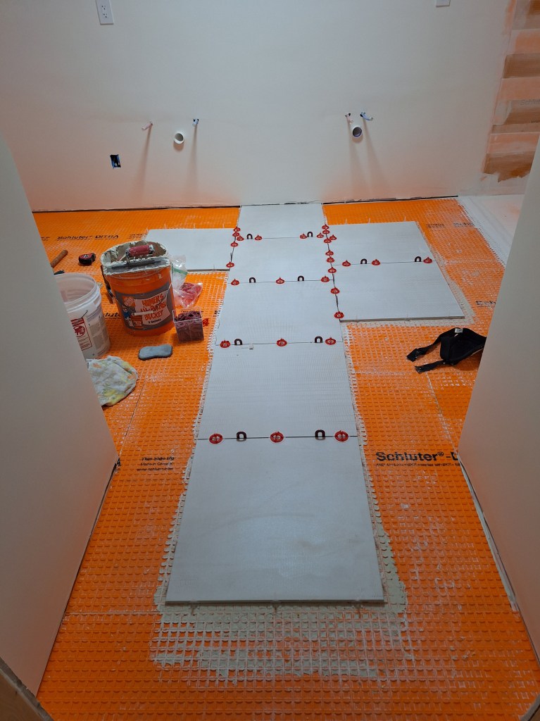
Setting – In progress.
In the image above, the full tiles are actually set and the others that required cuts (those surrounded with with the spacers) were just dry fitted. I used both a wet saw and a score and snap tile cutter to make the various cuts. In this shot, I had not yet gotten to the area around the entrance to the toilet alcove. Before this I realized that I would not have enough tiles to finish the entire area and would have to order another box of tiles. There are 4 tiles per box, and I was shy about 2 tiles. Since one cannot guarantee a perfect color match when placing a subsequent order, I made sure that the tiles from the new order would be in the area surrounding the toilet, making them less conspicuous if there was a noticeable color difference.
Here are the tiles set before I ordered the ones required to finish in the toilet alcove.
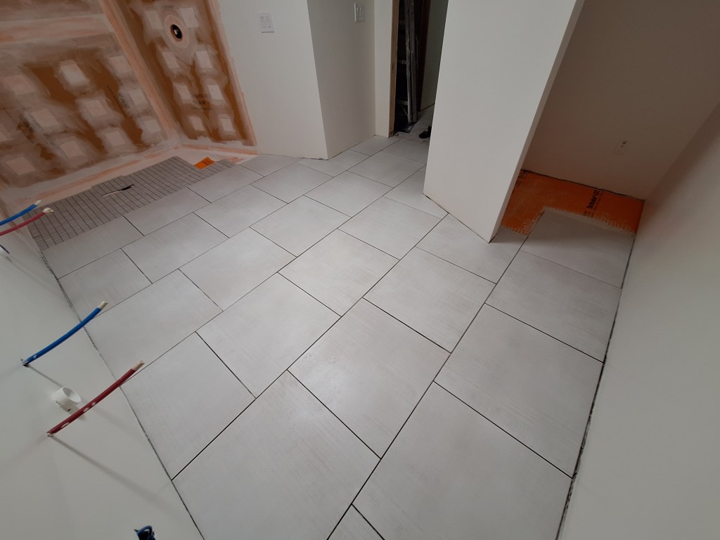
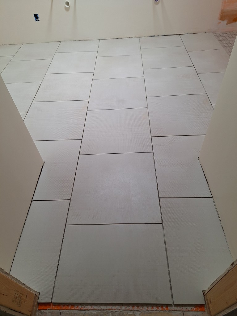
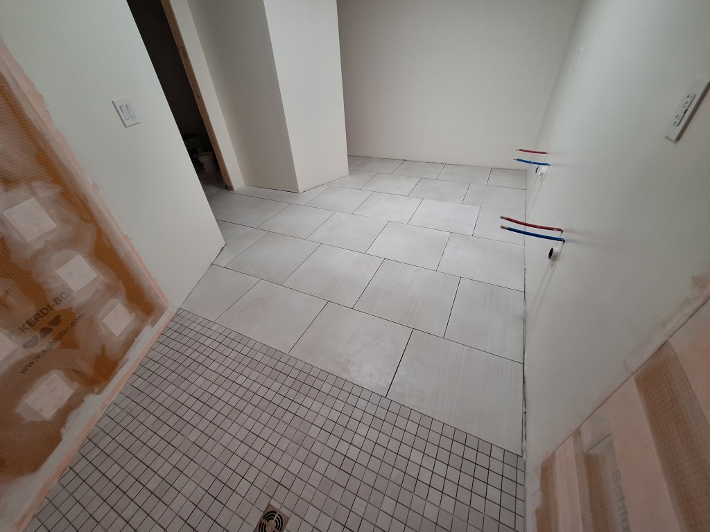
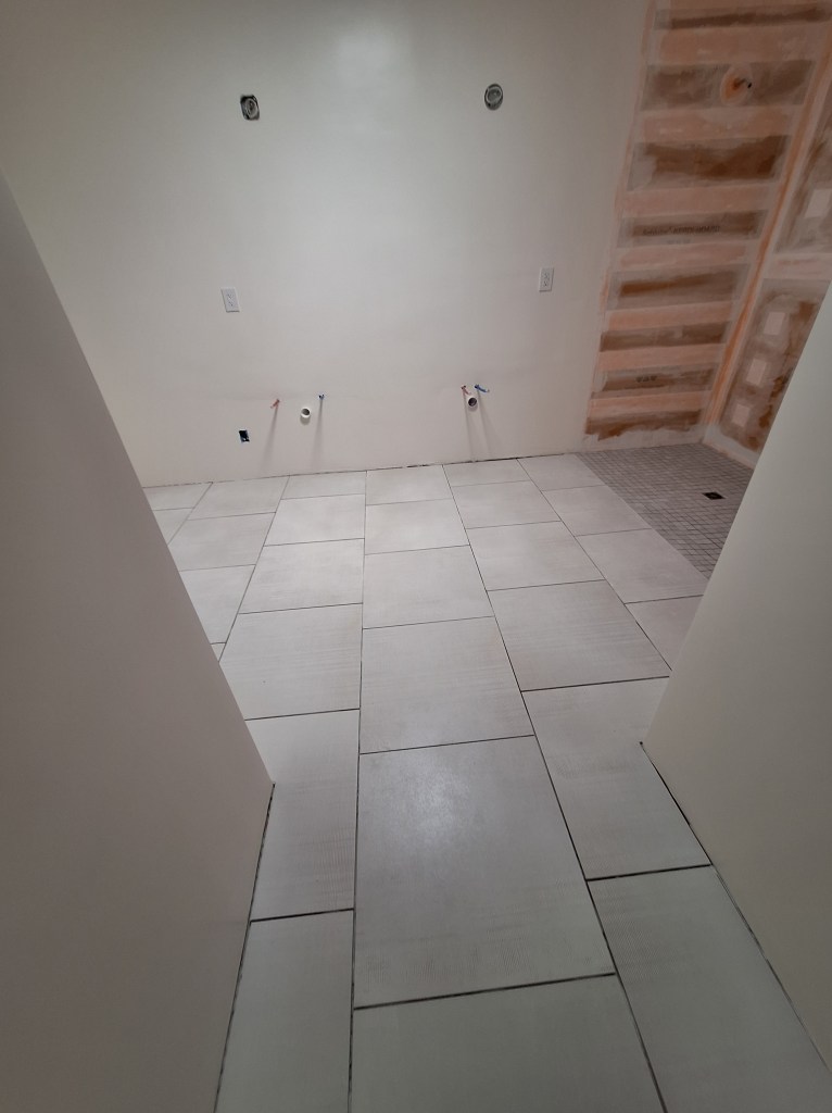
Tiles Set – Except in Alcove.
In the image above you can see I have one tile that extends into the toilet alcove. I actually have another from the original order that will take it right up to the wall, but I did not set it because I ran out of thin-set. Rather than mix up a small batch of thin-set for one tile, I would set it when I had some left over thin-set while setting the shower floor tiles. So the only area that will receive the new tiles will be left of that row – not very much!
Tiles Set – From Shower.
Tiles Set – From Entrance.
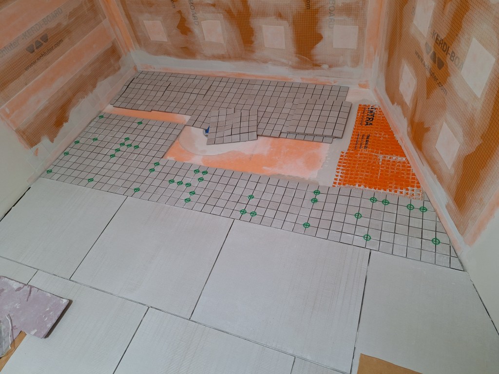
You can also see in the images above that I started arranging the mosaic tiles for the shower floor. Since I would have to wait for the additional floor tiles to arrive, I began working on that area next.
I started by cutting and dry fitting the tiles.
Dry Fit
The dry fitting process helps me decide exactly where I will start my tiles. Originally I had the tiles starting right up against the left wall (no partial tiles). With this arrangement, when I encountered the drain grate (covered in blue tape in the image above to protect it) I would have to cut the tiles on all sides to accommodate it. By moving the tiles over a bit (what you see above) to align with the grate, I’d only have to cut the tiles approaching from the top and bottom. Unfortunately, it meant I’d have only partial tiles against the left wall. Another compromise.
With that decided, I cut out the tiles to complete the dry fit and was pretty satisfied with the look. However, before I could set them in place, I had to build up the transition areas so that they would meet up with the bathroom tile and provide a more gentle slope down to the shower pan. I did this by building up those areas with some left over DITRA.
Adding DITRA to Ease the Transitions
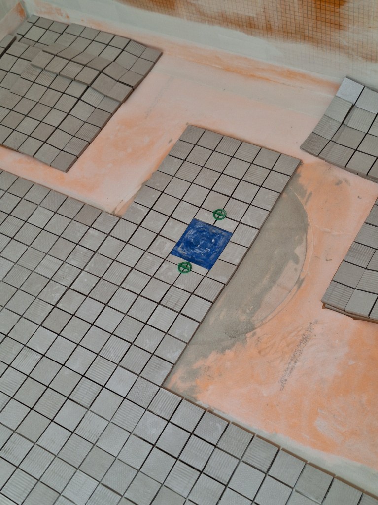
I then started setting the tiles, beginning with the front edge. Normally one would start from the back and work forward, but the most critical part of this process was the transition from the bathroom floor to the curbless shower floor, so I decided to set that first and let it cure over night before pressing on.
First Row Set (and a bit more).
I kept the dry fitted tiles in place where possible as I was setting the front row to use as a visual guide to ensure I remained on course. The added DITRA was very necessary and it, along with the thin-set, allowed me to get the mosaic tile to meet up nicely with the large format tile. That was the biggest challenge met. The next would be getting the grate set to the same level as the tiles that would surround it.
I was a bit nervous about setting the grate and tiles that surround it. I really needed to get this right, otherwise I’d be dealing with drainage issues forever. The grate itself needed to be set first (using thin-set), then the tiles after. Once the tiles were placed and while the mortar was still malleable, I could press down on the grate to ease it into alignment with the tiles. After that, I could add the four smaller tiles (two above, and two below in image below).
Setting the Grate and Surrounding Tiles
I was happy with the way it turned out. I had intended to continue setting tiles, but decided to stop and let it set up overnight before proceeding, to ensure this area would not be disturbed. I used the remaining thin-set I’d mixed up to set the remaining large format tile in the toilet alcove.
I then pushed on to complete the setting of the mosaic tiles for the shower floor. It’s not perfect, but I think it’ll be fine. From what I understand, grouting helps disguise many of the minor issues. I hope I’m pleasantly surprised.
I learned a lot from this, my inaugural tile installation. Tiling is a real skill. This took me way way longer than someone with experience, and many lessons were learned. I hope to improve in my future attempts.
Mosaic Tiles Set
I removed the blue tape from the grate just so I could see how it looked. I’ll cover it again when it’s time to grout.
Following are images of both the floor and shower tiles set. I will not grout until the walls tiles in the shower and the remaining floor tiles in the toilet alcove are set. I don’t want to be standing and working on a freshly grouted surface. Those tiles have been ordered and I await delivery at the time of writing. I had intended to post this only after the grouting was done, but since I may be waiting a few days and it is the end of the month, I figured this was a good place to end this post.
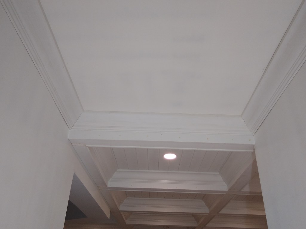
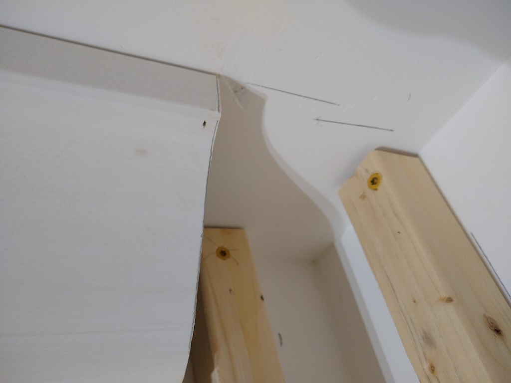
Having completed the long process of preparing the drywall in the kitchen, great room, and adjoining areas for priming, I was ready to put up crown molding in the foyer and entrance to master bedroom. Crown will also be added in the kitchen, but that will be done sometime down the road. The crown in the foyer and entrance to master matches that used in the coffered ceiling (the crown in the kitchen would not be so large). I started with the foyer.
What I thought was going to be a relatively simple task turned into a much longer one. It started out well enough. I ran my first piece along the wall above where the sconces will be (left wall in image below). I then put up the shorter piece facing the great room, followed by the next long span that ends at the front door. When I was installing that piece, it didn’t quite line up with my marks on the wall and ceiling. Here is the crown after three runs were fastened (before filling gaps), viewed from the front door.
View from Front Door
The image below shows the span of crown on the left side as you face the front door and where it misses the marks on the wall. It was also taken after I decided how to remedy the problem that ensued, which is why you see the blocking at the end (discussed in a moment).
Half an Inch high on the Wall
A closer look at where it missed the mark
I was happy with how it fit against the adjoining piece, but to get it to hit my marks on the wall would have pulled it way off the ceiling. So I pushed it into place where it wanted to go, leaving a half inch short of my wall mark, and a half inch long of my ceiling mark. But it looked good in this position, so I secured it. Something about the wall/ceiling along this span must have been off.
When I started on the final piece above the front door, it proved to be a real issue. I eventually realized that by missing my marks on the wall and ceiling, I’d changed the spring angle for the crown in that corner. Consequently, I had a spring angle of 45 degrees in the corner where I started (as it should be), and something around 50 degrees in the other corner. So I had to cut one end of the crown the usual way, and mess around with the saw to try and find a combination of settings that would give me a good fit on the other end. After too many attempts I quit for the day without success.
That night I decided to do something different. I was not convinced that I would be able to fit a piece of crown to pieces with differing spring angles, so I decided to introduce corner blocks in those two corners. Corner blocks would allow me to simply cut the crown at 90 degrees and butt it up against the corner blocks, thereby avoiding any need to align it with the neighboring piece of crown.
To prepare for this, I had to cut of the mitered end, making it straight, and install some blocking to fasten the corner block to. In the image below you can see both of these things. Also notice the pencil marks on the ceiling showing the difference from where I originally expected the crown to be and where it ended up. The distance between those two lines is approximately 1/2″.
Preparing for Corner Block
Of course I had to make the corner blocks too. Here is one of them.
Corner Block
Creating this took some fiddling, but I managed it and it installed nicely. I started with the right corner as you face the from door. A pretty good fit, with just some minor gaps to fill.
First Corner Block Installed
With both corner blocks installed, it was relatively easy to fit the final piece of crown between them.
Final Piece of Crown Installed between Corner Blocks
Here are some pics after I did the prep work for painting.
Crown and Corner Blocks Prepped
Crown Prepped
I then added crown to the entrance to the master bedroom. This was the last bit of crown needed to complete the areas adjacent to the coffered ceiling. This image below is before it was prepped for painting.
Crown added to Entrance to Master
With that done, I prepped it for painting and then proceeded to caulk the seems between the coffered ceiling and the walls – the area where I used the tear-away beads. With that done, I was ready to apply primer to all the walls and ceilings in the great room and adjacent areas.
However, before I started that I took some time to so some housekeeping, which involved some cleanup and organizing of the many cutoff pieces lying around, and the adding mobile bases to some of the cabinets I was using for tool and supply storage. The cabinets I’m referring to were from the original kitchen. They were well loaded with stuff, so moving them was a nuisance. Since I would have to move them into the kitchen to get at the ceiling in the great room, and then back again to get to the kitchen ceiling, taking the time to outfit them with custom mobile bases was well worth it. I was subsequently able to move them, fully loaded, with ease. So I proceeded with the priming.
For all the priming I decided to use a brush and roller. I originally thought I would use a sprayer, but the priming in the dining room went well using the old fashioned way, so I figured I’d continue that way. Also, the enormous amount of work required to mask everything off for spraying did not appeal to me, so I thought I’d stick with the brush and roller, at least for the priming. I may change my mind when applying the finish coats (stay tuned).
I started with the Foyer, both ceiling and walls.
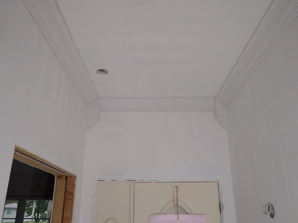
Foyer – Walls and Ceiling Primed
Foyer – View from front door
After the foyer, I primed the guest hallway ceiling and walls.
Guest Hallway Primed – View from Great Room
Guest Hallway Primed – View toward Great Room
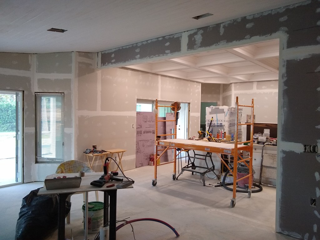
From there I started priming the ceiling in the great room. This took several days, after which I did the walls.
Great Room Primed – View from Foyer
Great Room Primed – View from Guest Hallway
Great Room Primed – View from Entrance to Master
Great Room Primed – North West view from Kitchen
Great Room Primed – View from Dining Room
Following that, I shifted all the furniture from the kitchen back to the great room so I could start priming the kitchen ceiling and walls. Sure glad I added the mobile bases. Here are some shots of the kitchen after priming.
Kitchen Primed – North East view
Kitchen Primed – South East view
That’s the refrigerator in the middle. No mobile base for it, so I worked around it.
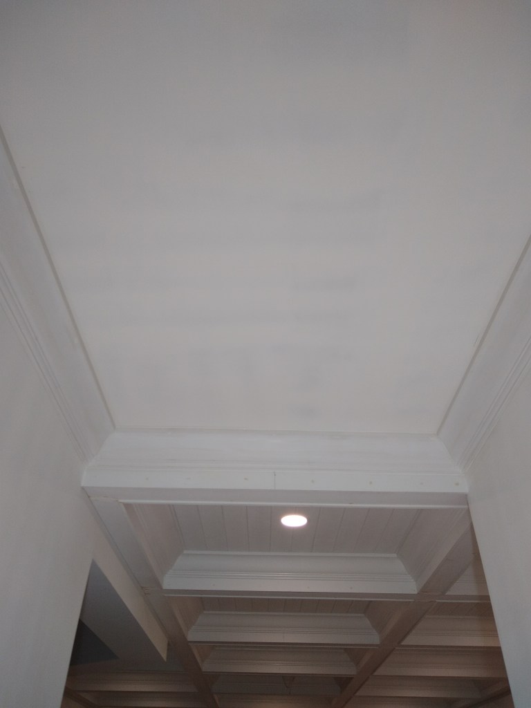
Kitchen Primed – Ceiling
I think the ceiling looks great. I’m haven’t decided on the final color, but I suspect it will be just white, much like what you see here. The great room ceiling, however, will probably not be basic white. I will probably do something a little off white, like eggshell. But I haven’t decided yet.
Note that because I have not yet added the crown to the kitchen ceiling, there are still gaps between the ceiling and walls. I’m not sure when I’ll get to that. It’s not a big priority, so I’ll get to it when I feel inclined.
In addition for the need for another inspection, as mentioned in a previous post, another reason I chose to continue working on the kitchen and great room rather than return to the work I was doing in the master bathroom was the psychological boost it would provide. That is, now that the great room and kitchen are looking close to what they will be when finished, it pleases me every time I enter the house. I can now better see what it will be, which enhances motivation.
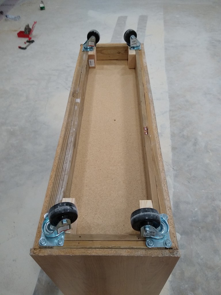
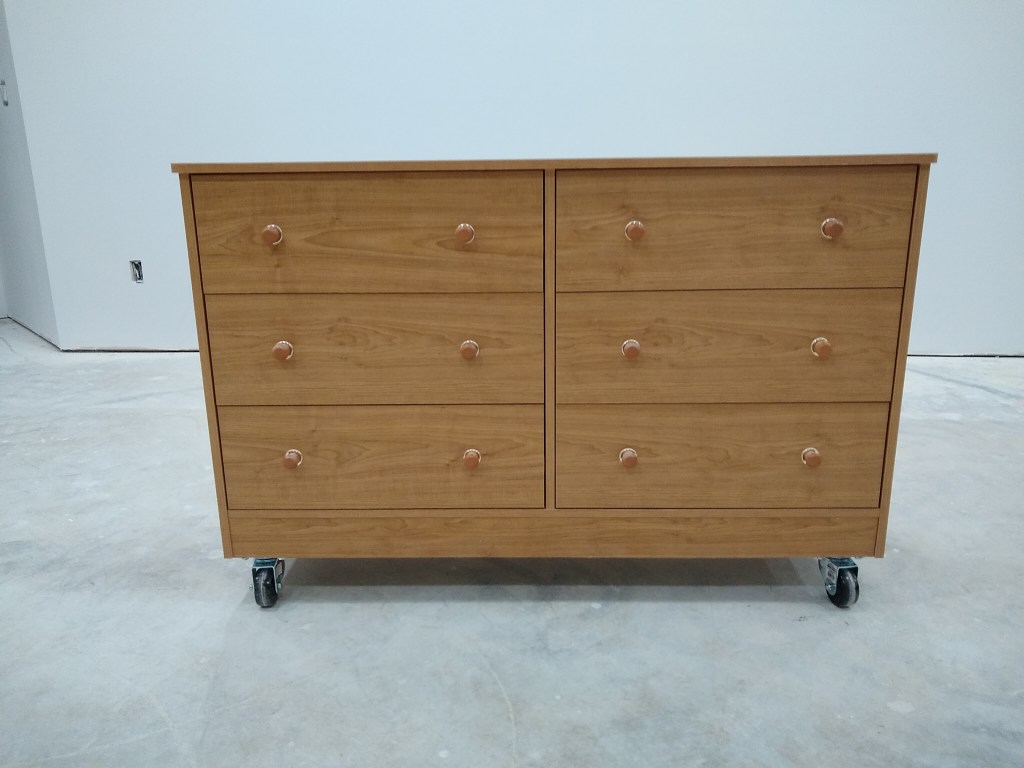
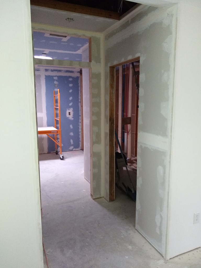
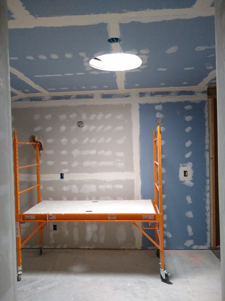
With that same spirit in mind, my next task will be to finish the drywall in the front two bedrooms, one of which I refer to as the workshop, and the other as the office. Both these rooms contain a lot of items that will have to be shifted before I can get access to the walls and ceiling, so some work will have to be done to make it easier for me to move things in and out. I will begin with the workshop and discuss that effort in the next post. However, before ending this post and my work at the house for 2023, I started preparing for the work in the workshop by adding a mobile base to a chest of drawers I use within it. Since I neglected to show my work on the mobile bases I mentioned above, I’m adding some pics of the mobile base for that chest of drawers to make up for it.
Mobile Base for Chest of Drawers
Note that, as with the other mobile bases I created, this is made using only off-cuts and scrap wood. It’s really great when I can make use of wood that might otherwise go to waste. Here it is mounted underneath the chest of drawers. A custom fit.
Mobile Base mounted underneath Chest of Drawers
Mobile Base from the Front
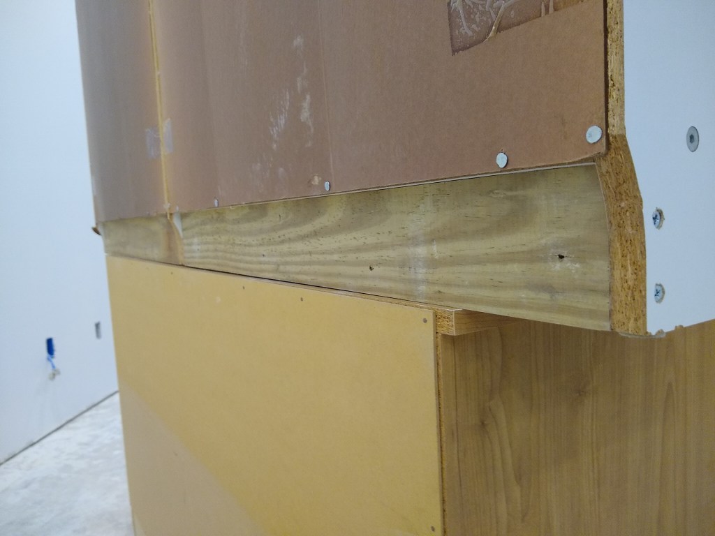
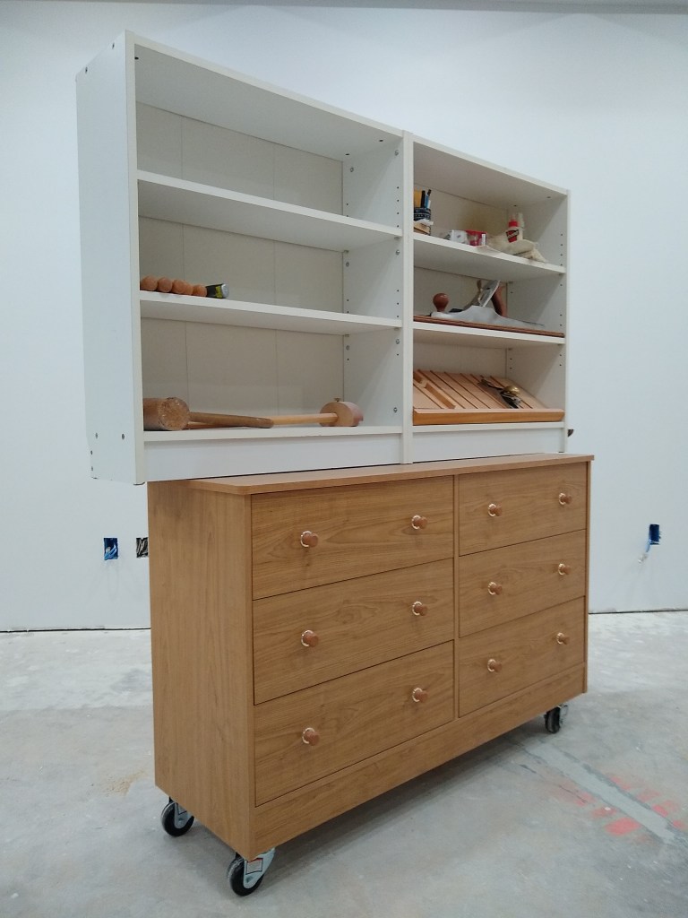
On top of these drawers I have a couple of shelving units I’ve had from since I was in university. They’ve worked so well that I intend to keep them, so I added some reinforcement to the back to help them sit solidly on top of the chest of drawers and then fastened them together to make them a single unit (although detachable if needed).
Reinforcement added to back of Shelving Unit
Since the shelving units extend past the edge of the top of the chest of drawers, the reinforcement (made for scrap) provides the needed support.
Attached Shelving Units on top of Chest of Drawers
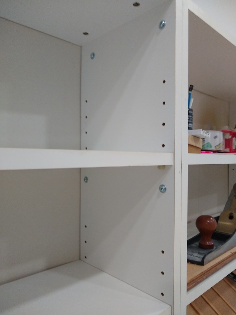
Above I’m showing both shelving units fastened together. They just sit on top of the chest and will not be fastened to it. Both will be pushed against the wall, so it will be secure as is. Following is a closeup of how I fastened the two shelving units.
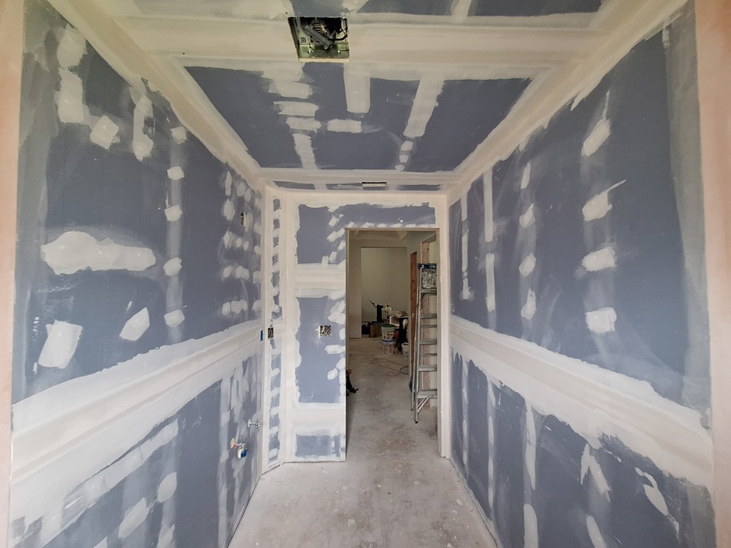
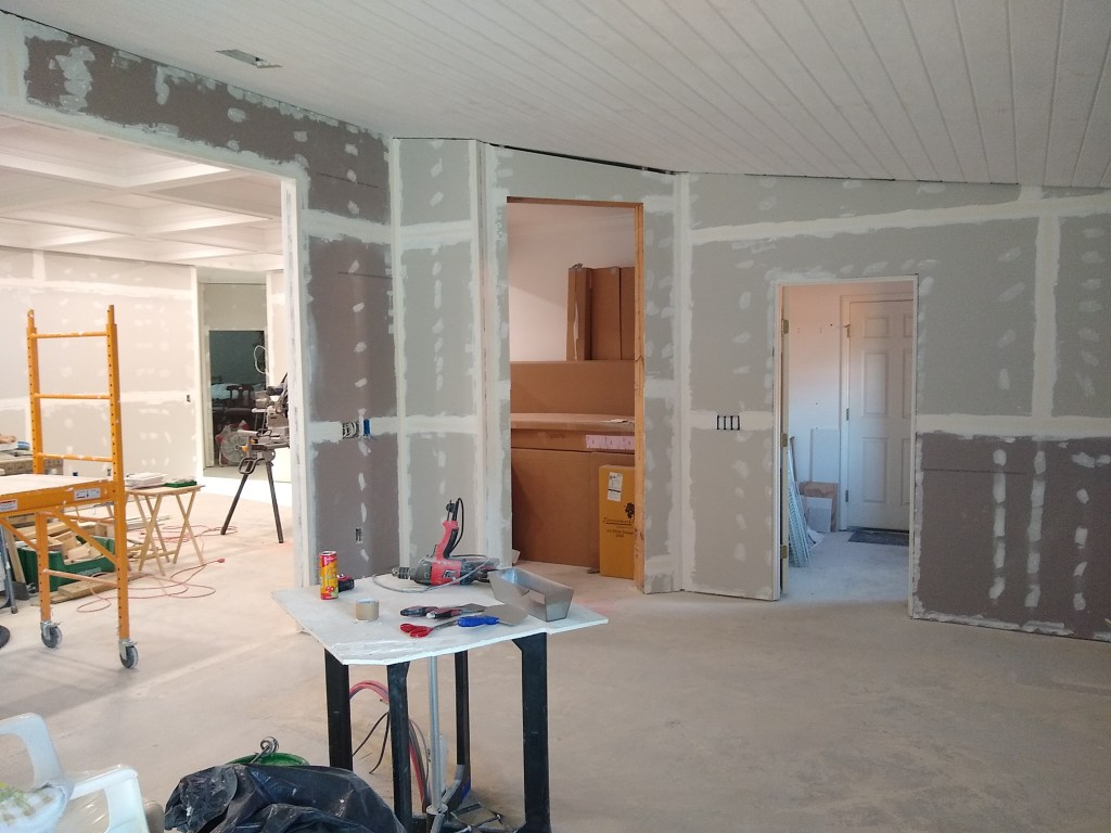
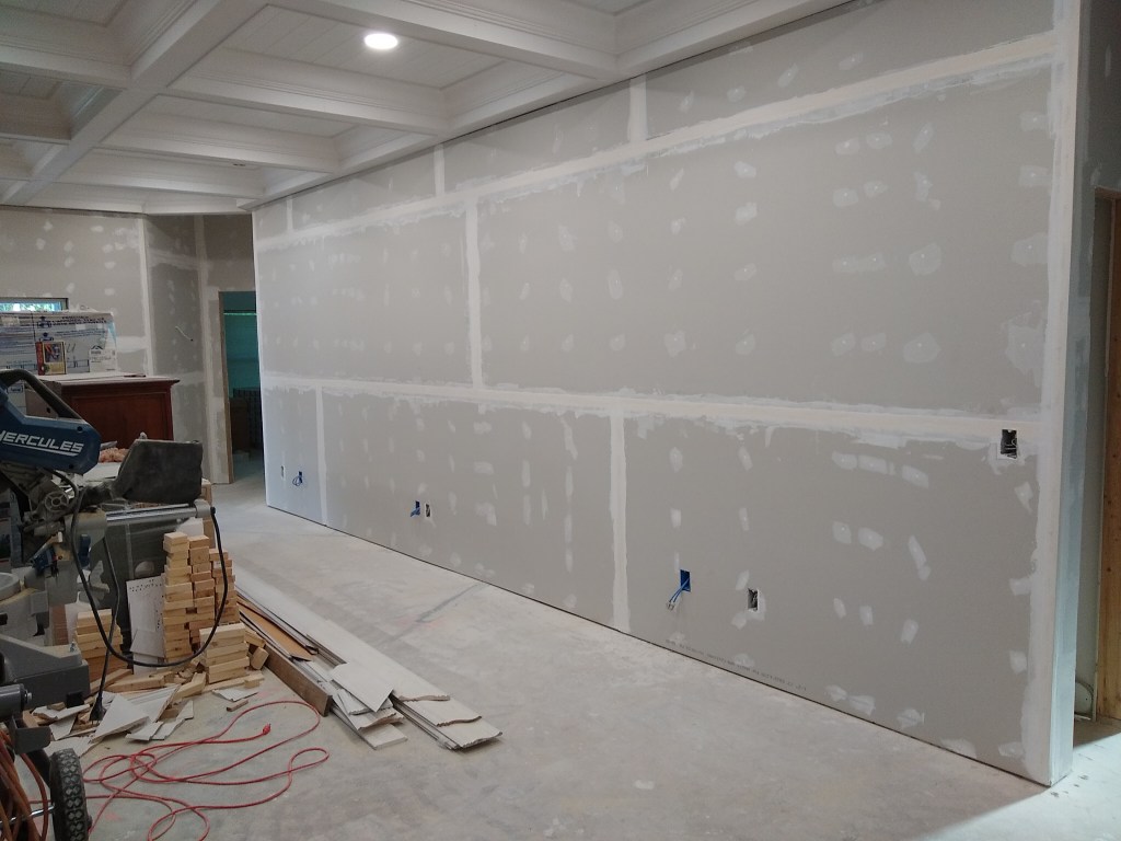
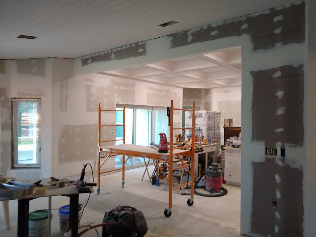
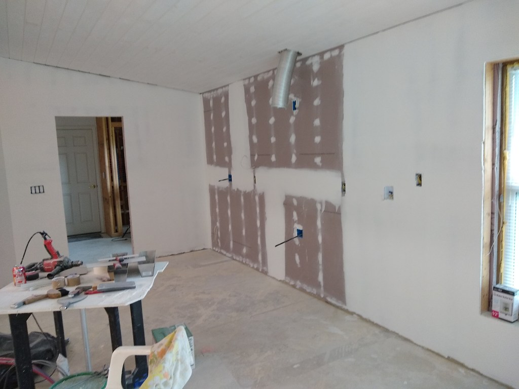
With the drywall hung (by the chimney with care) in the kitchen, great room, and adjoining areas, it was time to get busy finishing it. The first step, as usual, is to prefill, followed immediately by taping the joints. I started with the kitchen.
Taping – East and North Walls in Kitchen
Taping – North and West Walls in Kitchen
Taping – Bulkhead in Kitchen and South Wall in Great Room
Taping – South Wall in Kitchen
I didn’t strictly tape the kitchen first, then move onto the great room and such. Instead, I focused first on vertical flats, then horizontal flats, and then inside and outside corners. I do this because I want to have the tape ends covered by successive taping so there are no dangling tape ends. That is, after doing the vertical flats, the ends of the tape will be covered by the runs of horizontal flats. The ends of the horizontal flats will be covered by the inside or outside corner beads. The ends of the corner beads will be covered by trim (either baseboard, crown, or something else). This isn’t really that important because it all gets covered during the coating phases, but I like overlapping the tape ends this way. So, even though I present the pictures by room, it wasn’t done in that order. Here are the other areas I taped.
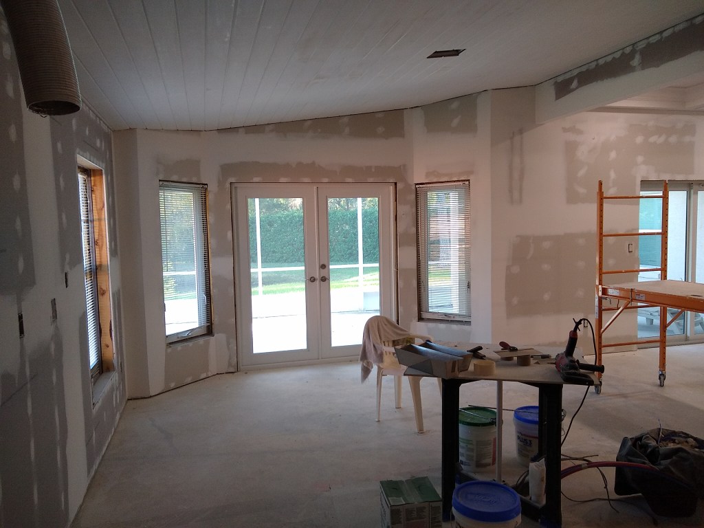
Taping – West Wall of Great Room
Taping – East and South Walls of Great Room
Taping – Guest Hallway
Taping – Foyer
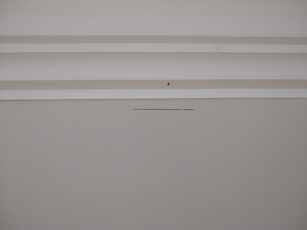
Note that in the images above, the top edge of all the walls that adjoin the coffered ceiling still have gaps. This area is addressed using a tear-away bead, which I mentioned in a previous post. Here are some images after the tear-away bead was installed.
Tear-away Bead – West Wall of Great Room
Tear-away Bead – Bulkhead adjoining Dining Room
Notice how the gaps are now closed. Here are some closeups along the bulkhead adjoining the dining room
Tear-away Bead – Bulkhead
Tear-away Bead – Closeup
The tear-away beads are both glued and stapled. The glue is sprayed onto both the vinyl bead and the drywall. After you give it a bit of time to get tacky, you press it in place. Whether the staples are necessary is questionable, as the glue is very strong, but I did it just to be safe. Here is the same image I showed in a previous post of how tear-away beads work.
Tear-away Bead
Drywall mud is used to cover the bead, using the little lip under the tear-away strip as a surface to guide the drywall knife as if the knife were a screed. Once the bead is sufficiently coated, the tear-away strip is pulled off (shown above) to leave a crisp straight edge along the adjoining surface. At least that is how it’s supposed to work. What’s important is that once the tear-away strip is removed, the gap between the wall and ceiling should be very small, and easily filled using caulk. I like the idea of having the two surfaces (drywall and wood) neatly interface without the need for trim. Using this approach still leaves me the option of using trim if it doesn’t turn out the way I’d like. However, at this stage I was optimistic about this approach.
With the taping done, I moved on to cover coating. I applied two cover coats over the tape and the tear-away beads. For cover coating in general, I use lightweight mud for both coats. However, for the first cover coat of the tear-away beads, I used all-purpose mud. This was to ensure the vinyl strip was well adhered and covered. I used the lightweight mud in this area for the second cover coat. Here are the images.
Second Cover Coat – East and North walls in Kitchen
Second Cover Coat – Bulkhead in Kitchen
Second Cover Coat – South wall in Kitchen
Second Cover Coat – West wall in Great Room
Second Cover Coat – Entrance to Master
Second Cover Coat – Guest Hallway
Second Cover Coat – Foyer
You can also see in the last three images above that I added junction boxes for the sconces: two in the foyer, one in the guest hallway, and one in the entrance to the master bedroom.
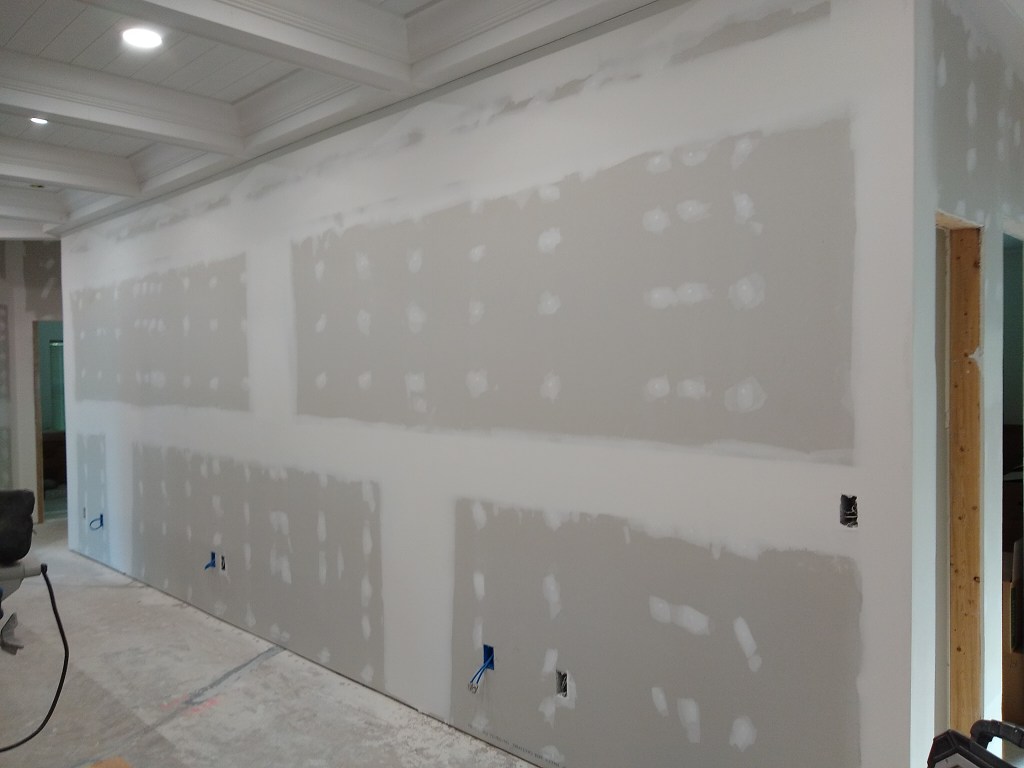
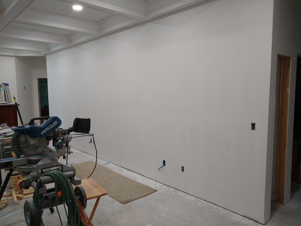
I then proceeded to skim coat all the surfaces. The first skim coat was a thicker one than the second. After each skim coat, I sanded. After the first skim coat, I sanded using my sanding poll with some hand sanding. After the second skim coat (a tight skim), the sanding was done strictly by hand and with an inspection light to make sure it was just right. So this took a long time. The pictures below only show the final result because it would not add a lot of value to show intermediate stages, which I’ve done before. Although it looks like the walls are painted, they are not. Priming and painting will be the next stage in finishing the walls.
Second Skim Coat – East and North walls of Kitchen
In the image above, I did not skim coat the area where the cabinets will go. No point skimming a wall that will be covered by cabinets.
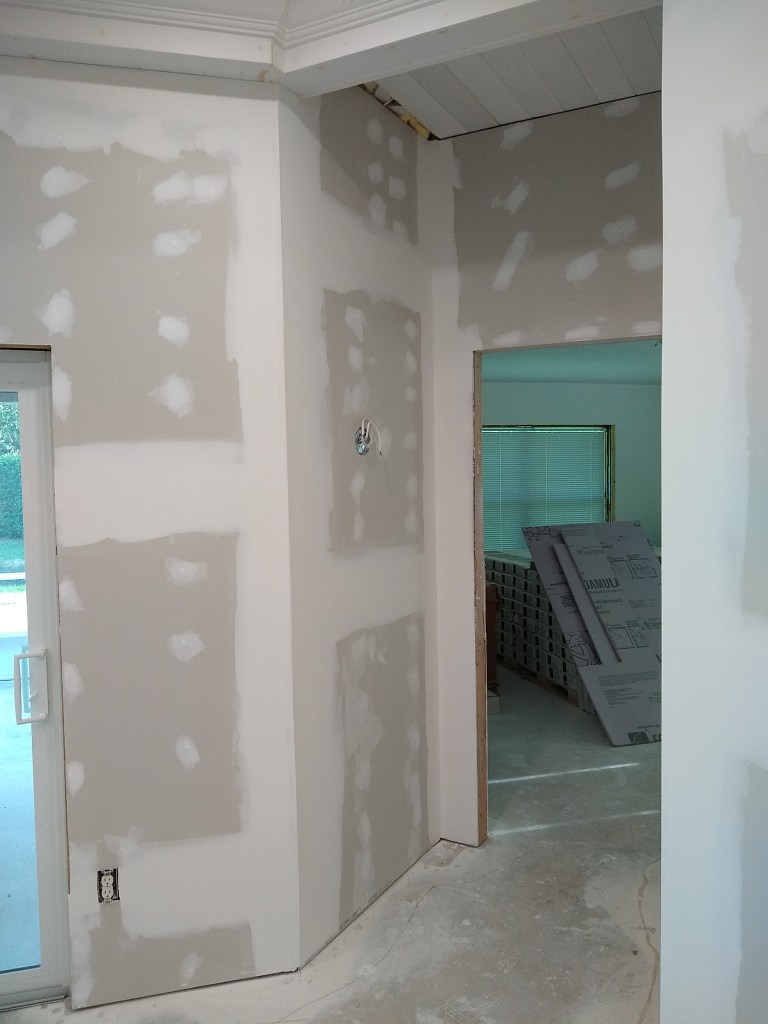
Second Skim Coat – Entrance to Dining Room from Kitchen
Second Skim Coat – Bulkhead in Kitchen
Second Skim Coat – South Wall in Kitchen
After the second skim coat, I pulled off the “tear-away” part of the tear-away beads. Here is a closeup of that.
Removal of Tear Away Bead after Second Skim Coat
I was very pleased with how that went. It left a nice line between the drywall and the wood of the coffered ceiling. I will fill the small gap with caulk in preparation for painting. I think it will look very seamless once I’m done. In all images that follow, the tear-away beads have been removed.
Second Skim Coat – North Wall in Great Room and into Guest Hallway
Second Skim Coat – West Wall in Great Room
Second Skim Coat – South Wall in Great Room and Entrance to Master
Second Skim Coat – Wall Between Great Room and Kitchen
Second Skim Coat – Foyer
With the walls skimmed out, the next job is to put up crown molding in the foyer, entrance to master, and in the kitchen. Then it will be time to do any additional prep work before I start priming the ceiling and walls in these areas. That will be covered in the next post.
Before any shower walls go up, there is some preparatory work required. I added a nailer to the left side of the wall and, of course, the sound insulation had to go in.
Sound Insulation on Back Wall
Before putting up the Kerdi board, and in order to make tiling easier, I spent some time locating the high and low spots in the framing so that they can be compensated for. The idea is to make the walls as flat as I can so that I don’t have to struggle with undulating surfaces during tiling. To do this I employed a technique known as wet shimming. I discovered this online and thought it made good sense, so I gave it a go. The idea is to identify the parts of the studs that need to be brought out a bit and put thinset mud on them. Then, when applying the boards, you use a straight edge (my longest level) to press it into place. The thinset should collapse a bit under the pressure applied by the straight edge. I used the screws and washers to keep it in place, but did not secure them. That would be done the next day after the thinset had setup and was strong enough to maintain its shape.
Wet Shimming lower half of back wall
And here is the first Kerdi board set in place.
First Kerdi board in place
The next wall I tackled was the one where the shower head would emerge. It proved to be difficult because it was not at all flat.
Shower Head wall ready for Kerdi board
If you look closely, and at previous pics, you’ll notice that I removed a stud. That stud was severely bowed. I started by planing it, but that would have taken forever. After realizing it wasn’t supporting anything (no drywall screws on the other side), I pulled it out. I then cut it up into shorter pieces and straightened them on my little 4″ jointer to use them as nailers for the shower head wall. You can see them if you look in the corner. That made things much better. I still needed some wet shimming, but not too much.
The Kerdi board for that wall went up vertically, as opposed to how I did the back wall. Doing it this way meant less seems to address later.
Kerdi board on Shower Head wall
The wall with the mixing valve was next, along with the bits remaining on the top.
Kerdi board on all walls
Something I should have done before putting up the Kerdi board, was test the water connections for leaks. That was a silly mistake and one I won’t make when I do the shower in the guest bathroom. If there was a bad connection, I would have to pull off some of the Kerdi board to address it. So I attached a small bit of PEX to the drop ear elbow where the shower arm will go and hooked up the water lines. I turned them on and was happy to see there were no leaks. Actually, I would have been surprised if there had been any because I’ve never seen a PEX crimp connection fail. Still, it was a relief to see no leaks. You can see the makeshift shower head I created in the image below. I did this just before I started adding Kerdi band to waterproof the walls.
To waterproof the walls, all seems must be covered along with all fasteners and any other penetrations (intended or accidental). Kerdi band is applied much like drywall tape, except using a special Schluter thinset. I started with the horizontal seems.
Horizontal seems and some squares
For the shower head wall, which is the shortest length wall, I decided to use a full length of Kerdi band rather than cutting little squares. I did this because I saw it done online and thought it would be a good idea. For the longer back wall, I did it the usual way by covering each fastener separately with a square piece of Kerdi band. After trying both, I actually preferred doing the little squares. It seemed easier to me, and faster. Perhaps with more experience I will change my mind. After this, the thinset I mixed up ran out, so decided to call it a day.
The next day I tackled the inside corners, including one vertical and the three that meet the ceiling.
Inside corners and more squares
Once again, I didn’t mix up the right amount of thinset, so I ran out before completing the job. You can’t store thinset, so you have to guess how much you’ll need. Mixing it up is a process. You have to get the ratio right and then it takes 5 minutes of continuous mixing, followed by 10 minutes to let it “slake”, then another 3 minutes of mixing. And you can’t just put the new stuff in the bucket with the remains of the old stuff you just used, like you can with drywall compound. So cleaning up is also a process. It’s not just about cleaning the mixing bucket, but also the tools have to be cleaned, and the dirty water used to clean everything needs to be disposed of outside so it doesn’t mess up your drains. Consequently, I only want to do the cleanup at the end of my day. So when I ran out of thinset this time, with time still left in the afternoon, I bailed out and decided to do the cleanup and then head home rather than mix up another batch.
The next day I replaced my makeshift shower head with the real thing, since that opening would need to be waterproofed too. In doing that, I ran the water again to make sure there was no leak between the shower arm and drop ear elbow in the wall. Even though I placed a bucket under the shower arm, there was still some spillage. You can see evidence of that by the water in the pan area.
All walls done
With that done, I added the remaining Kerdi band, finishing up with the two circular pieces: one around the mixing valve, and the other around the shower arm. Further waterproofing will be needed between the walls and the shower pan, once installed. But I won’t do that until the walls and ceiling in the bathroom are skim coated and primed. I’ll also wait until the ceiling is painted; not only to eliminate the risk of spilling anything on the shower pan, but also so that I don’t have to put a ladder, or whatever else I need to reach the ceiling, on the shower pan. Once the shower pan is in and waterproofed, it will need to be guarded to ensure nothing punctures it until the tile is in.
Before starting the first skim coat on the ceiling, I had to cover coat the Kerdi band between the shower and the drywall, which included the ceiling. I used all-purpose mud for that. After that dried, I applied the first skim coat to the ceiling.
First Skim Coat Ceiling – above shower
First Skim Coat Ceiling – rest of Master Bathroom
As with the other rooms, I give each new surface (walls and ceilings) two skim coats before primer and paint. I let the first skim coat dry overnight then gave it a light sanding before applying the second skim coat.
After the first skim coat I discovered an issue. Before leaving for the day, I decided to take my 6.5′ level and check for flatness along the walls. The long wall where the vanity will go was not at all flat. It was quite wavy, actually. For some reason I never thought to check for that before hanging the drywall. It would have been at that time when I could have easily corrected for it. In one area it was 7/16th of an inch out. This would be evident once the vanity was in place and the backsplash installed, so I had to do something to even it out. This meant “mud framing”, which involves adding a ton of mud to make up the difference.
I started by simply applying all-purpose mud to the low spots to build them up. With such an amount of mud, it would take a couple of days for it to dry before I could put another layer on. So I decided to switch to hot mud, which would dry in a matter of hours. Also, I decided that rather than just slap it on and slowly build it up, as I started out doing, it might be a good idea to create “mud ridges”; a term I just made up. The idea is to just put down mud in the deepest troughs and use a straight edge as a screed to flatten the ridge relative to the higher parts of the wavy wall. They look like this
Mud Ridges
Mud Ridge closeup
In the closeup you can see how thick the mud is. That is how much was required to bring it up to the level of the adjacent parts. Once that dried, I would use it and the other end of the wall that were at the same level to support the screed and even out the mud.
Creating these mud ridges didn’t take long, so I had to find something else to do while I waited for them to dry. I could have started the second skim coat on other parts of the bathroom, but I’d just ordered a set of skimming blades by a company called Level-5, and wanted to wait for them to arrive. So I decided to do some prefilling of the drywall I installed long back in the guest hallway and elsewhere.
Guest Hallway Prefilled
Foyer Prefilled
Dining Room Prefilled
The next day I returned to the master bathroom to build up the recesses in the vanity wall to meet the mud ridges. I used 90 minute hot mud.
Building up the recesses
As you can see, the mud ridges are no longer obvious. The surface is still pretty rough, but improving. At this point I just had to let the mud dry overnight before checking for flatness. Even though I used 90 minute mud, it was put on quite thickly, so it would take some time to dry. I didn’t expect it to be flat yet. I just wanted to see evidence that I was getting closer.
My fancy skim blade set arrived.
Level-5 Skimming Blade Set
The longest blade in this set is 32 inches. My hope was that it would speed up the skimming process and provide me with nice flat surfaces. I tried using them on the wavy vanity wall as I continued to fill it, but they didn’t help much. I think they are best suited to skimming walls that area flat to start with. So I ended up building up the wall using my 14″ blade (not part of this set) until it was close enough. Eventually I got it to a point where it was far from flat, but good enough that it shouldn’t be obvious with the vanity and mirror in place, which is all I ask.
I then proceeded with skim coating the walls. As usual, I did two skim coats and it resulted in this:
Second Skim Coating
Second Skim Coating
In the images above, it not only received two skim coats, but also was prepped (i.e., sanded) for primer. It almost looks like it has been painted, except you can still see some of the blue drywall color in places. I was pretty happy with the result. Definitely a level 5 finish.
The next few days was all about priming and painting. As with the master bedroom, I primed all surfaces with a single coat, then applied two coats of paint to the ceiling. I will leave the walls with only primer for some time. I’ll probably do the final painting just before I’m ready to put the flooring down. Following are images of the walls and ceiling after priming and painting. Because the walls are still to be painted, I did not mask them off when painting the ceiling, letting the ceiling paint get on the walls at the junctions.
Entrance Hall Primed and Ceiling Painted
Entrance Primed and Ceiling Painted
Entrance to Shower
Shower Area
Main Area of Master Bathroom
In the image above you can get a sense of how the vanity wall came out. It looks fine to the naked eye. Let’s hope it remains so once the furniture is in place. Also, the walls look a bit streaky in the picture above. They are not. That is just some light reflection. The primer on the walls looks good and consistent.
Outside of Toilet Alcove
Inside Toilet Alcove
Inside Alcove showing Ceiling Painted
At this stage I am ready to put the shower pan in, but that will be put on hold until I address something else. I ordered my wood flooring quite a while ago, thinking I would need it by the fall. The company I purchased it from was willing to hold it that long, but after doing some estimating, it is clear to me that I won’t be ready for that for a very long time; well into next year, given my pace. As a result, I am going to have to find space in the house to store the flooring, since they will grow impatient with me after the fall. I’ve decided to store it in the dining room. In general, I’d like to have all the painting (walls and ceiling) done before the flooring goes down to avoid the need for drop cloths. However, once the flooring arrives and is stored in the dining room, it will seriously limit access to that area. So I’ve decided to finish the walls and ceiling in that area before the flooring arrives. I’ll return to the master bathroom once that is done. In the next post I’ll be covering the work in the dining room.
Continuing with the master bathroom, I hung more drywall. I started with the ceiling on the other side of the door. While technically not part of the master bathroom, I’ve decided to include it here because it is the hallway to the master bathroom and I will be working that area at the same time.
Hallway Ceiling to Master Bathroom Hung
Above you can see where the new attic access will be. I haven’t decided yet if I’ll have drop down ladder or simply put a cover that can be pushed up and out of the way so that a ladder can be put in place. More research will be required for that.
With the ceiling out of the way, I could start working on the walls. Walls are far more “fun” than hanging drywall on the ceiling, so it was nice to be able to graduate to the walls. I started with the west wall, which is an exterior wall. As usual, the insulation went in first and then I started hanging the boards.
First Sheet on West Wall
West Wall Hung
This was the easiest wall to work on because it was straight and required no cut-outs.
Before hanging drywall around the toilet alcove, I had to fasten the water supply line. I picked up some dedicated hardware for that.
Toilet Supply Line Fastener
I like this because it did not require a 90 degree connector. I could simply bend the PEX 90 degrees and fit it to the metal bracket. I also added supports for the rest of the line as it rose to the ceiling.
Supply line fastened to Stud
After adding a couple of staples to keep the wires from the switch box together and secured to the stud, I put up the drywall around the outside (only) of the toilet alcove.
Outside of Alcove Hung
Before enclosing the electrical in drywall, an inspection was required, so I turned my attention to preparing for that. This meant securing any wiring I hadn’t and adding the required spray foam in the openings where the wire enters from the attic, which acts as a fire block. I also secured the water supply lines to the vanity, which I show below.
Vanity Supply Lines Fastened
Here’s a closeup.
Closeup of Supply Lines fasteners for Left Sink
I scheduled the electrical rough in inspection on the weekend, so I had some time to wait for that, so I started hanging drywall in the places where I do not need pre-approval. This meant I could start on the entrance to the master bath and just inside the master bath.
Left side of Hallway
Below I show a picture of the work in progress just so you can see that I have added sound insulation.
Right side of Hallway in Progress
Right side of Hallway Complete
Other side of Hallway Entrance
In the image above you’ll notice that I used some of the left over pieces I had of the water resistant drywall (blue). They were a suitable size, so I used them. I try to use as many of the off-cuts of drywall as I can. I have many hanging around, so I always look for opportunities to use them before cutting up a fresh sheet.
While working on the area I’m showing above, the inspector came and gave me the green light, so I was free to cover the rest of the master bathroom walls. Ideally I’d have started work on the shower, but the materials I ordered still hadn’t arrived, so I pushed on hanging drywall. The toilet alcove was next. As usual, I added sound insulation first. Very important in this area ;-).
Walls of Toilet Alcove Insulated for Sound
Even though the toilet alcove is not fully enclosed (no door), adding the sound insulation does make a difference. It noticeably deadens the sound. The drywall was added next.
Alcove Drywall Hung
The next day, my kitchen cabinets arrived!
Kitchen Cabinets in Garage
But there is an unfortunate story behind this, so we’ll take a bit of a detour before returning to the work in the master bathroom.
I first purchased cabinets from Chris Haley in December of 2019. I have referred to Chris on multiple occasions in much older posts. I paid in full for the cabinets and the installation. When Covid became an issue a few months later, I stopped work on the house. I contacted Chris and asked him to have the cabinets delivered. I wanted store them in the house because I didn’t want the order just hanging out there indefinitely. I didn’t know when I would resume work on the house. He was adamant that I not do that because of warranty issues, and that it was best to leave them in the warehouse of the manufacturer. So I took his advice and backed off.
It turned out that Chris’ insistence was really due to the fact that he never ordered the cabinets. When the time came to have them delivered, he stopped communicating. I could not reach him via phone, text, nor email. He blocked me. I did have one avenue open to me and that was via the fellow who he worked through to order cabinets. His name is Jared and just happens, by coincidence, to be someone I know. We used to work at the same company and had come to know each other from our mutual interest in working out. It was just a fluke that I discovered his relationship with Chris. One day Chris learned where I used to work and mentioned that his supposed “silent partner” Jared worked there too. When he told me Jared’s full name, I exclaimed “I know him!”. So that was kind of cool. Of course, this was way back before I knew Chris hadn’t ordered the cabinets. Jared was an engineer, but did this cabinet thing as a side hustle. It was only through Jared that Chris was able to get cabinets. So Jared was important to his business.
I hadn’t spoken with Jared in years, so when I could not get in touch with Chris, I contacted some former colleagues and they were able to put me in touch with Jared. My subsequent conversation with Jared made it clear to me that Chris never ordered the cabinets. Jared explained that no manufacturer would store cabinets for very long, let alone years. He was of the opinion that Chris could not have ordered them. Jared also tried to contact Chris, but he too had been blocked. It wasn’t quite as simple as this. It happened in stages, but I won’t bore you with the details. The bottom line is that I am no longer in contact with Chris and the money I gave him.
Fortunately, Jared did me big favor. Although he had nothing to do with this fraud, he volunteered to allow me to purchase the cabinets I wanted through him at his cost. That was very nice of him and I was very thankful for his help. We spent an afternoon at his house going over my order and he was able to steer me in the right direction. He was also able to speak directly with the delivery driver and the cabinets were delivered directly to my house. Normally they are delivered to Jared’s warehouse where I would have to rent a truck to pick them up and drive them to the house. So, despite being ripped off, my experience with Jared made this a whole lot better. Thank you Jared! Jared has since shut Chris off. Chris is no longer able to order cabinets through Jared. We both do not know what he is up to. I decided not to take legal action because it would mean more expense and effort that would likely not result in any benefit. I’m quite sure Chris doesn’t have any money, so would likely just declare bankruptcy. I mentioned the incident in a review on his web site and decided to move on.
Although I may never know, I don’t think Chris originally intended to rip me off. I suspect that when he cashed my check at the end of 2019, and knowing I would not be needing the cabinets for some time, figured he had plenty of time to place the order. That money should have been sitting in a separate business account, but I bet he wasn’t that organized. So it was probably just a pile of money available to him. He probably had some more pressing financial issues/desires at hand and used the money for them. After all, he kept in touch with me for more than three years, so he probably figured he’d come up with the money when needed (Charles Ponzi would relate). When time ran out, he just ran away, so to speak.
So that is the background and I am pleased that I now actually have kitchen cabinets. I’ve since moved the cabinets into the house to store them in an air conditioned space. I gave them a quick inspection and they looked fine. I’ve left them in the boxes to keep them from harm and then got back to work on the master bathroom.
Returning to the main thread, i started work on the vanity wall by first adding sound insulation.
Sound Insulation added to Vanity Wall
Lots of nooks and crannies, so this was a bit of a chore. Since this wall backs onto the guest bedroom, it was important to add the sound insulation. This will also be added, and probably most importantly, to the area around the shower. The first board I added was the one that will be right beside the shower, so it was a moisture resistant board.
Blue board adjacent to Shower
Unlike most of the boards I hang, I put this one up vertically. I did this because there was a pair of studs on the left edge where I could fasten it and retain the bevel (i.e., no trimming). But I also liked the idea of having no seem to tape, except up high, where there is unlikely to be any risk of splashing. It probably doesn’t really matter, but that is why I did it. The rest of the wall was hung in the usual manner.
Vanity Wall Hung
I used regular drywall for the area further from the shower. Being far enough away from the shower, I didn’t think there was a need for the moisture resistant variety. I used some of the off-cuts of the blue board to cover the small area up top.
The wall adjacent to the shower entry was also hung using the blue board, since it too is subject to splashing.
Entry to Shower
I figured that after hanging the drywall, I would start working on the shower, but the Schluter products I ordered had still not arrived, so I pushed on with prefilling the gaps in preparation for taping.
Prefill – Entry
Prefill – Vanity Wall
After some light sanding, I moved on to taping.
Entry Hall
Vanity Wall and Ceiling
Toilet Alcove
Entry to Shower
While this was being done, I picked up the Schluter shower system materials and the floor tiles. But I didn’t just switch to working on the shower. Instead, I decided to continue with the drywall and take it further, adding two cover coats over the tape.
Toilet Alcove
Vanity Wall
Inside Toilet Alcove
Shower Entrance
Entry Hall
After the cover coats, I would normally start the skim coats. However, I decided I would leave that until the shower had been waterproofed. The waterproofing would have to interface with the drywall I just coated, and that interface will require a kind of taping that will overlap with the drywall. So I did not want to apply any finishing coats only to have to redo it at that interface. In preparation for hanging the Schluter Kerdi boards around the shower walls a few things would have to be done. The first was to hook up the shower valve and add water hammer arrestors.
Shower Valve hooked up
This was done on the last day of June. Tomorrow, I start putting up the walls around the shower. But that will be chronicled in my next post.
The master bathroom is getting some serious changes made to it from what I originally intended. My initial plan was to include a tub, kind of like this:
Original Plan for Master Bathroom
But after some thought I decided not to include a bathtub. I originally purchased this tub:
Tub I intended to use.
This tub was acrylic. It looked nice, but was not substantial. A cast iron tub was more what I had in mind, which would cost a significant amount more. After some thought, I decided it didn’t make sense given the cost and limited use it would get. I haven’t had a bath is a very long time. It would sure look good as the center piece to the bathroom, but in reality it would not be used very often and would just be something I’d end up cleaning far more than I would use it. So I decided to pass on it. I sold the tub on Craiglist.
The new design without the tub will look something like this:
New Plan for Master Bathroom without Tub.
One of the first things I needed to do was remove the PEX lines I had for the two vanities that were originally going along the west wall (wall on the right in image above) and reroute the vanity wiring. Below you can see two blue and two red PEX lines, and to the right of them is wiring for the vanity.
PEX and Wiring for Vanity prior to change of plan.
Here is a shot after I removed them.
West Wall and Ceiling of Master Bathroom
Notice that I’ve just pushed them up into the attic for now. I will eventually bring them down into the wall once I know what vanity I am getting. This is necessary because the vanity I choose will dictate where the lines need to go. I will pull the hot and cold lines originally intended for the bathtub up into the attic and just leave them there. Although I don’t have a use for them, I don’t see the point in pulling them out completely. They will remain routed to the Manabloc, just not hooked up. If, someday, I find a use for them, I won’t have to climb up there and run them (just reroute).
You’ll notice from the image above that the ceiling is no longer in place. I decided to pull down all the drywall on the ceiling in the master bathroom. This was primarily motivated by my desire to reposition the sun tunnel. It was installed in a position that was not centered on the entrance to the master bathroom, so I always thought it looked a bit odd. To fix this I would have had to create a round opening in the ceiling, maybe a foot or more to the right (as you look at the image below), then patch the original opening. That would be a tricky proposition.
Sun Tunnel
There was also another other issue that contributed to my decision to pull down the ceiling.
Entrance To Master Bathroom
I also intend to move the attic access from where it is now in the large closet to the entrance hall to the bathroom. Having attic access in the closet would severely limit what I could do in the closet with respect to cabinets, so I needed a better location, and I think the hallway will do. That change required some ceiling demo too. I wasn’t entirely sure where to put the opening within the hallway. After demoing the ceiling, I was able to get a better idea of it. I decided I would put the opening near where the A/C vent is shown above. So I’ll reposition that vent to a more suitable location.
In doing this demo, I removed the wall that had been framed between the shower and the large closet. This wall was secured to the ceiling by sandwiching the existing ceiling drywall between the top plate and the joists. With the drywall removed, I that wall will be rebuilt and attached directly to the joists before the drywall is replaced (assuming I use drywall). Here is an image of that area after the wall was removed.
Framed wall between Shower and Large Closet removed.
Below you can see the north wall and ceiling after the demo. You can still see the PEX intended for the bathtub, which, as I mentioned, I’ll pull up and store in the attic. You can also see where I rerouted the wires (yellow for outlets and white for lights).
North Wall
With the ceiling removed, I have much more flexibility with respect to positioning of ceiling lights and vents. Although I did not originally intend to remove the ceiling, I’m glad I did.
Following the demo, I got to work re-framing the wall I pulled down.
Closet Wall Framed
I also added nailers in anticipation of the drywall and ceiling work that would come.
Nailers at Top of Framed wall from Outside of Closet
Nailers at Top of Framed wall from Inside of Closet
These were a bit tricky as it involved many very acute angle cuts. I attached 2x4s to the top of the top plate so that half of one of the 2×4 was overhanging on the outside and half of another overhung on the inside. This will provide a good amount of surface to attach the wall and ceiling covering.
Next I moved the A/C vent and centered the sun tunnel, as mentioned above.
A/C Vent and Sun Tunnel Moved
The A/C Vent will now reside on the other side of the door (when framed), providing more direct A/C to the bathroom. The sun tunnel required a bit of surgery, as I had to remove part of an insignificant board between the rafters that prevented me from putting it where I wanted. I then added a couple of nailers between the rafters to create a square to firmly capture the circle and provide something proper to attach to. In the image above, I have inserted the circular flange and used a couple of clamps to hold it in place until the ceiling is installed and I can attach it permanently.
Now that I am no longer locating the vanity sinks on the west wall, the drain that leads to them is no longer needed, so I pulled out the shovel and started removing the dirt to get access to the drain. To my surprise, the pipe had several cuts which would have happened when I hired someone to cut out the concrete. Fortunately, I was pulling out this pipe anyway, but it made me look closely at the rest of the pipes. Although I didn’t take a picture of the cut pipe, here is an image of the area after I removed the cut portion. You can see the cut lines in the concrete on the left half of the image.
After Removing the Cut Drain
Having seen the damage to the pipe I removed, I had to check the drains from the toilet, where the same crew removed that concrete too. Sure enough, it was damaged.
Cut Toilet Drain Pipe
Notice the cut across the pipe in the top half of the image and the scoring near the bottom. There is also significant scoring from the concrete saw in the middle of the pipe along its length. So this had to be pulled out and replaced. I was planning to open all this up for the inspectors, so it’s not like it would have gone undetected. It’s just a nuisance really.
Below I show how I used my reciprocating saw to cut out the damaged section.
Cutting out Damaged Section
The pipe you see to the right is what was left of the drain from the original toilet location. That is now just a dead section of pipe. I capped the end, which was probably overkill. Here is the new pipe.
New Toilet Drain
After this I called for and inspection to get the okay before filling in the trench. As I was waiting for the inspection, it occurred to me that the drain location for the vanity was kind of far from the wall. So I measured the distance and, sure enough, it was. After all, it was positioned to service a bathtub, not a vanity sink. Although the vanity cabinet would cover it, it would still be right there as you opened the door under the sink. So when the inspector arrived I discussed this with him and he agreed it needed to change. Essentially, what I did was restore the drains to what they were when the house was built. Here’s what I mean.
New Drain Configuration for Vanity
New Drain Configuration for Vanity
This is much simpler. The drain to the original tub remains capped, but that is the only extraneous pipe in the system. The inspector, who was a plumber for more than 30 years, recommended I use the black flexible rubber couplers you see. These made all the difference when trying to squeeze the pipes into position. The next day I ran water through the pipes with no evidence of leakage. Later that day the inspector returned and gave me the green light to fill in the trenches.
To fill in the trenches, I have to have the soil treated for termites, cover the soil with a plastic barrier, and install rebar before I pour the concrete. I called my pest control guy right away and arranged to have them come out. It would be a few days, so I got to work preparing the rebar. This meant drilling holes and cutting and arranging the rebar in a grid pattern. Here’s what I came up with.
Rebar for area under Vanity
Rebar for area under Toilet
Note that in the images above, the rebar is not attached yet. That will happen after the soil has been treated and the plastic barrier has been put down. So I removed the bars and set them aside so they would not get in the way as the soil was treated.
After the soil was treated, I put down the plastic and secured the bars, then summoned the inspector to give me the okay for the pour.
Under Vanity, ready for Concrete pour.
Under Toilet, ready for Concrete pour.
The inspector gave me the okay, so I mixed up the concrete and started filling in the trenches.
Concrete added to Vanity trench.
Concrete added to Toilet trench.
I used almost seventeen 60 pound bags of concrete mix, and mixed it together with water in a 5 gallon bucket. I gradually added the mix to the water at the bottom of the bucket and used a small trowel and a mixing drill (with appropriate bit) until the texture was right. This was a lot of work. A concrete mixer would have been ideal, which is what I used the last time I did this. But that required I rent a pickup truck in addition to the mixer because my vehicle is not big enough to transport the mixer. The inspector was the one who suggested I use the 5 gallon bucket, which worked just fine. It was a bit slow, but didn’t involve a long drive and the hassle of renting.
I left the concrete to cure for a week before I resumed work in the master bathroom. I would be drilling screws into some of it when I put up the walls around the toilet, so I wanted to make sure it was well set. I also needed to get together with Jennifer (the designer) to settle on the vanity, mirrors, and lights so that I know where locate the electrical boxes and make any adjustment to the drains (in the wall) while they are still accessible. She would not be available for a couple of weeks, so I turned my attention to the kitchen while I waited (you should jump to Kitchen – April 2023 now if you want to follow the April 2023 time line).
After finishing up the work I wanted to do in the kitchen, I returned to the master bathroom where I felt comfortable that the concrete was fully cured. So I framed the toilet alcove.
Toilet Alcove Framed
Recall that I had done this a long time ago, and when I removed the walls to redo the plumbing, they came down in two fully assembled pieces. However, rather than simply reinstall these two pieces, I pulled them apart and started from scratch. I did this because I am a better framer from when I first did it and wanted to do a better job. I am pleased with this. Below you can see where I added some more framing (nailers) to help with drywall installation, added the wiring, and pulled the cold water line down from the ceiling where it had been patiently waiting for so long.
Alcove Wiring Added
If you look closely to the left, you can see that I took this picture after framing the entrance door. I actually forgot to get a picture of the wiring I added to the alcove, so took it while I was capturing pictures of the door framing, which I got to right after the alcove wiring was done. Here are a couple of better shots of the door framing.
Entrance Door Framed – looking into the bathroom.
There is quite a bit of space above the header of this door, so I’m thinking of adding a window in that space. I think it would provide additional light during the day while not affecting privacy.
I will end this post here because I must wait for the delivery of the vanity I purchased for this bathroom. I need that to arrive so that I can get specific measurements so that I can determine where to locate the water supply lines, drains, and electrical. It is not expected to arrive until early May, so I might as well wrap up the April post here. However, before I do, here is a pic of the vanity I purchased. It is a dual sink, 84″, white oak free standing vanity.