Interior Doors – February through May 2026

After considerable time off for the holidays and beyond, I slowly got back to work starting in February. It’s funny the role momentum plays. Having not done any construction work on the house since moving in, getting back to it required a bit of a push.

My attention initially turned to interior doors. A lot of time was spent just thinking about what I wanted. I visited a local door supply company and was given some brochures. After identifying a style I liked, I initiated an email exchange with the contact I made while visiting. That went on for a bit, then the guy didn’t return my most recent email. Unfortunately, this is not uncommon in this industry. So I left that for a while, which turned out to be a good thing because during that time I came up with an idea for the interior doors I hadn’t initially considered. I’ll get to that later.

While all that thinking was going on, I was getting a bit frustrated with the lack of any tangible work. I had to do something – anything. So I decided to install the jambs for the two closets in the master bedroom.

Jamb for Small Closet
Jamb for Large Closet

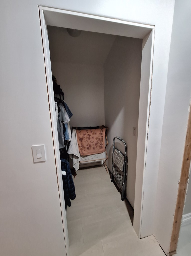
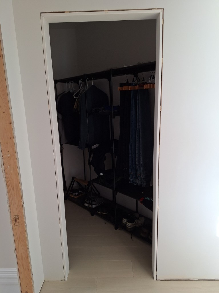
I will not add doors to these closets because the entrances are in a small hallway, which provides enough separation. I would end up keeping the doors open all the time. Also, when open, they would limit access to some of the closet space. Without doors, the jambs could be simple. No need to accommodate a specific door size. These openings will eventually be trimmed out with casing and adjoining baseboard, but that will come only after my interior doors are installed.

I was holding off on continuing work in the guest bathroom because I needed the door to it to be installed first. Once the door was installed, I could install the door casing. Once the casing was installed, the baseboard would butt up to it. The baseboard needed to be installed before the toilet because the toilet would get in the way. So there is an order that these operations must follow. Since I was still in flux with respect to the doors, I realized there was a way for me to make some progress in the guest bathroom, even without the door in place.

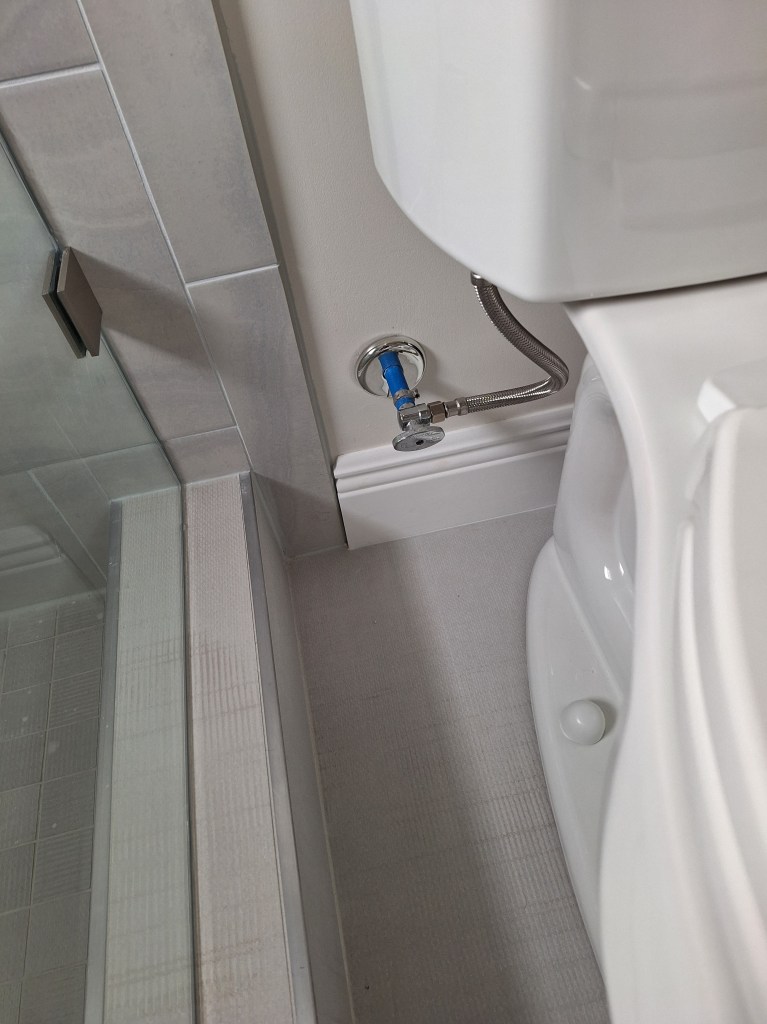
I knew where the vanity was going to go, so all I needed to do was install the section of baseboard that goes behind the toilet and fits between the shower and vanity. So I got to work on that.

The only fiddly bit to this operation was adding a return to the end of the baseboard section that goes up against the shower tile. The other end simply butts up against the vanity.

Adding a Return to the Baseboard

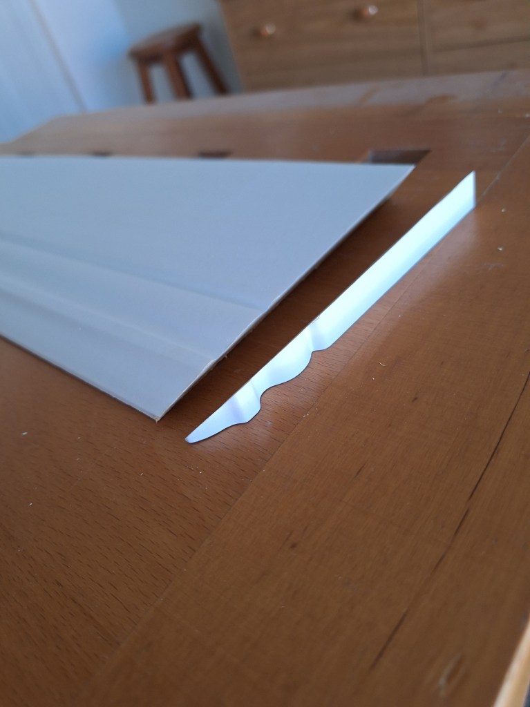
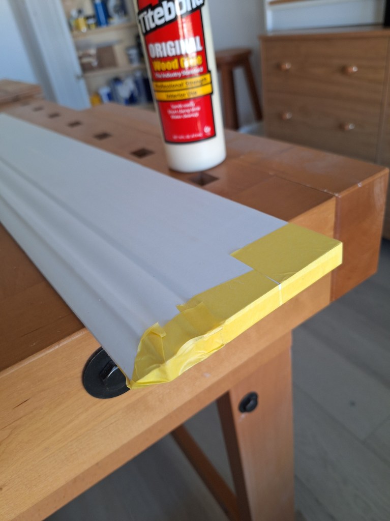
To make a nice termination where the baseboard meets the shower tile, I cut a 45 degree angle and added a small piece that will butt up against the wall. I then used glue and tape to fasten it.

Return Glued to Baseboard
Tape Removed

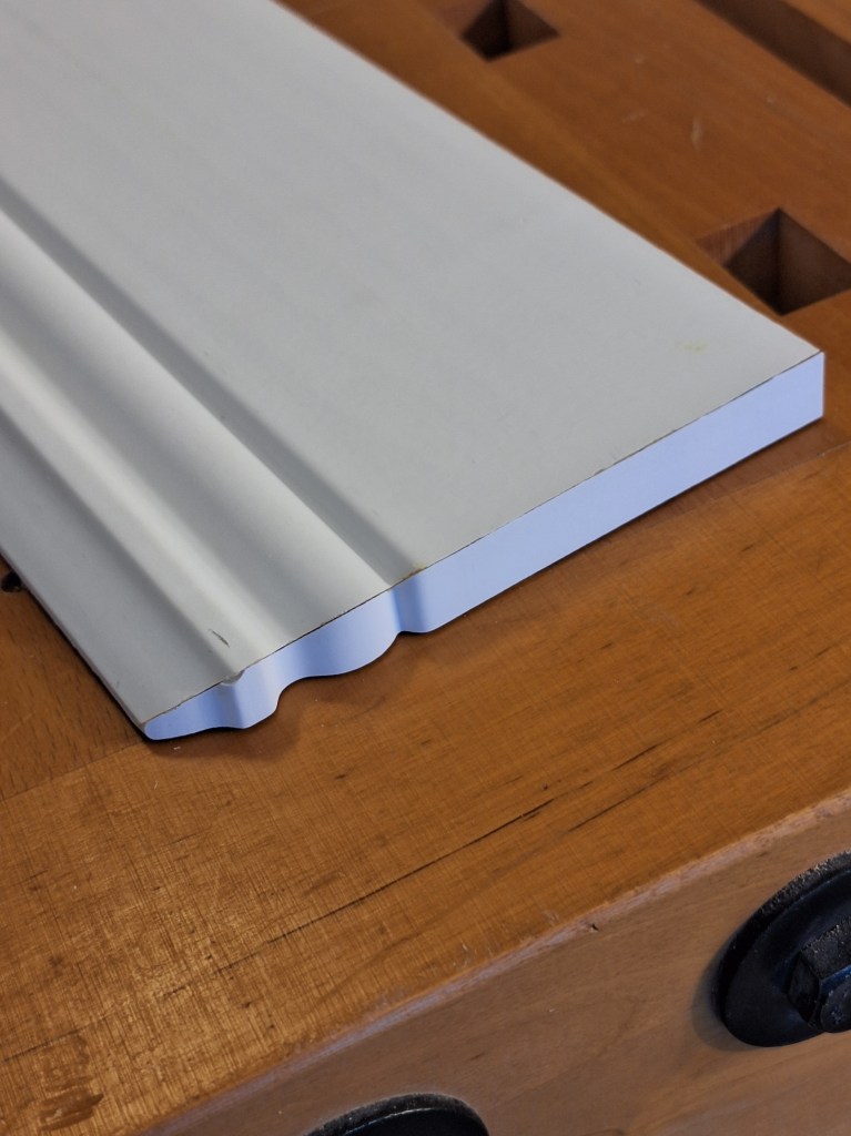
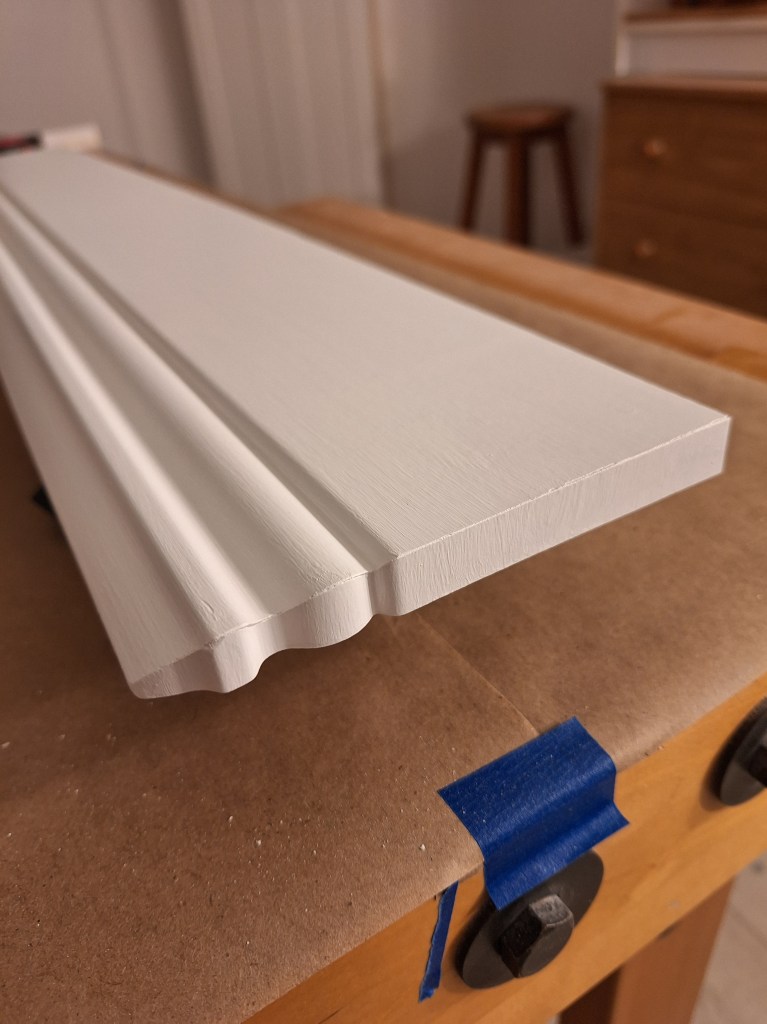
After a bit of cleanup and painting, it looks like this:

Baseboard ready to Install

Here it is installed behind the toilet.

Baseboard Behind Toilet Installed

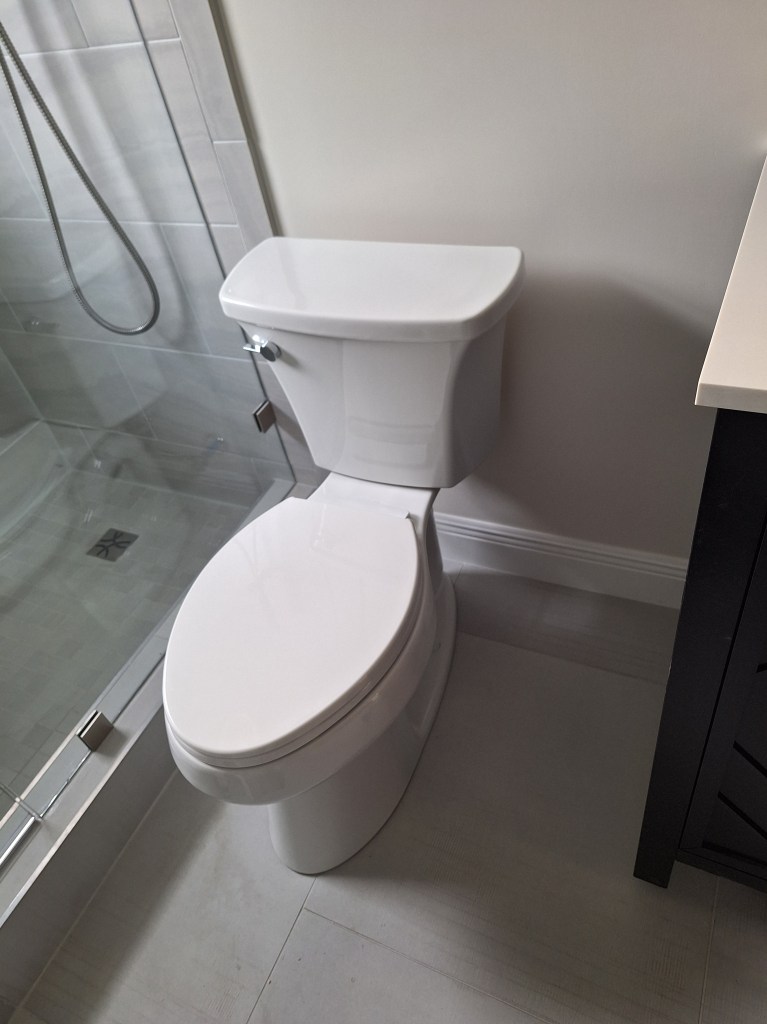
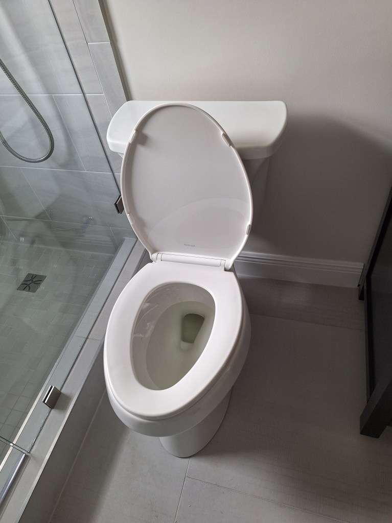
And here are a couple of pics of the toilet.

Toilet Installed
Toilet Installed – seat up.

Now I had to return to the interior door situation before I could continue with the bathroom. After reaching out again to the door supplier with no response, I decided I was going to make the doors myself. This has been common theme throughout this renovation. It is not uncommon for people in this industry to lack enthusiasm for new work. Perhaps they have so much of it that they can’t be bothered to follow up with new customers, or it is a cultural thing. I may never know, but it strikes me as very odd to engage with a potential customer and subsequently ghost them. Regardless of the reason, it has, and hopefully will continue to be, a blessing. Had the people in the various trades been more conscientious, I would not have taken on the things I have in this renovation. I have learned so much and have, in retrospect, been very happy that I was left with little choice but to do things myself.

Having decided that I would make the doors myself, I gained a significant degree of flexibility. I could make one door at a time, make them custom sizes, and if I desired, could make each door in a different style. As such, the plan for now is to make couple of “statement” doors: one for entrance to the master bedroom; and the other for the entrance to the workshop (in the foyer). Currently, my thinking is that these statement doors will be done in something dark, like walnut, while the other doors will be painted white to match the trim work. But I’ll figure that out later. In the interim I had to learn how to make my first door. So I did a lot of research and decided to use poplar. This is a relatively soft hardwood, is easy to work with, and paints well. It is commonly used for solid wood doors that will be painted. I hunted around for rough sawn 8/4 lumber (i.e., 2 inches thick) and learned that it would take a while before what I wanted would be in stock, so rather than waiting, I decided to get some 3/4″ boards from HomeDepot. What they offer there is not rough sawn (so it’s expensive) and does not come in 8/4 thickness, but I could use what they have to create an half scale prototype door to learn on.

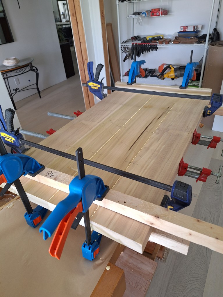
I bought two 6 foot long boards that were 5 inches wide and 3/4 inches thick. I glued them together to get to the thickness I wanted (close enough). Although this would only be a half scale model, I wanted the thickness to be much like what I’d have for the end product.

Two Boards Glued Together

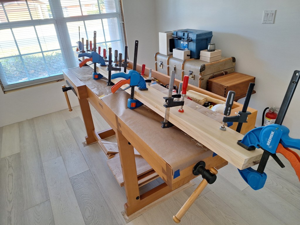
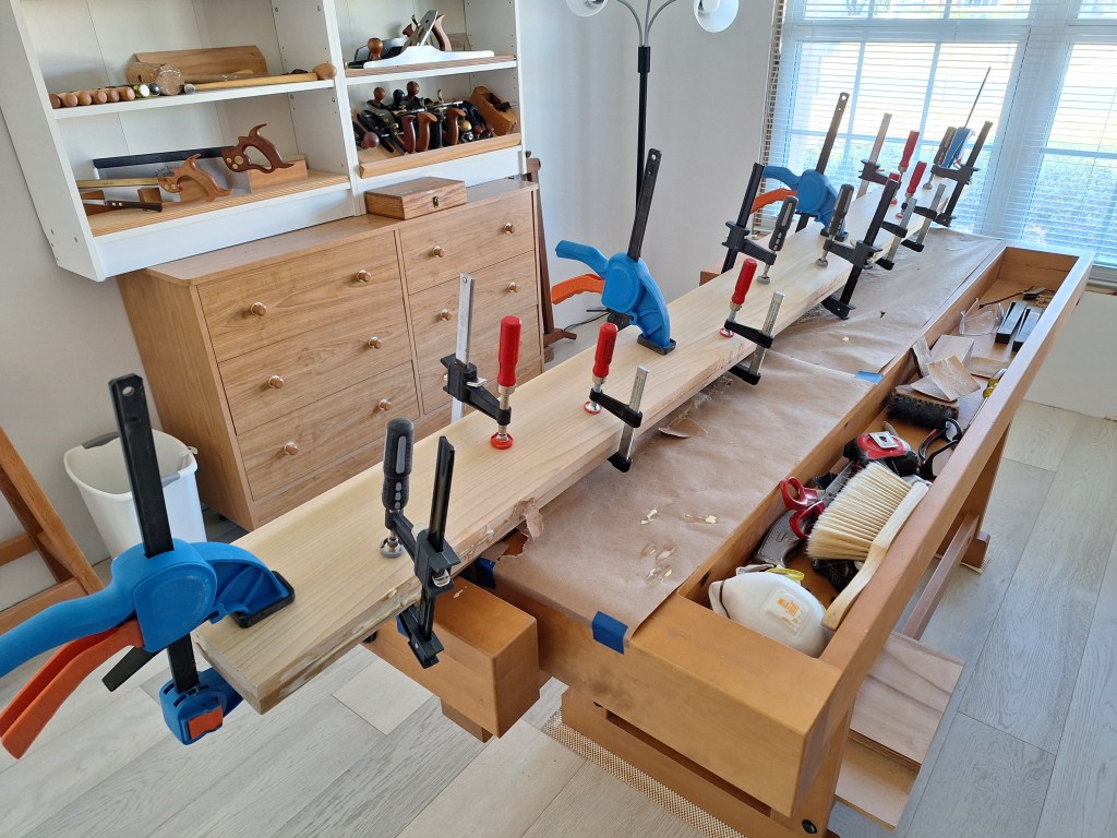
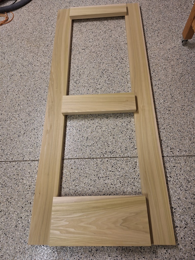
Once they were out of the clamps, I cut out the rail and stile pieces I’d need. This resulted in two stiles of about 42″ each, and 5 pieces for the rails.

Stiles and Rails rough cut and loosely positioned.

The door for the guest bathroom will be a two-panel door of height 81″, width 33″, and about 1-1/2″ thick. As such, it will have three rails. The stiles will be 6″ wide horizontally, the top rail will be 5″ wide vertically, the middle (or “lock”) rail will be 6″ wide vertically, and the bottom rail will be 10″ wide vertically. Since the prototype I’m building here is a half scale, these dimensions will be about half that – doesn’t have to be exact.

Each of the rail pieces I had after cutting up the board were about 2-1/2″ wide. This was fine for the top rail (2-1/2″ = 1/2 x 5), but the lock rail and bottom rail would need to be wider than that (3″ = 1/2 x 6″, and 5″ = 1/2 x 10″, respectively). So I glued up a couple of pieces to make up the difference. Rather than take them to the 3″ and 5″ they should be, I left them wider than that. Being a prototype, these dimensions aren’t critical. These will be close enough.

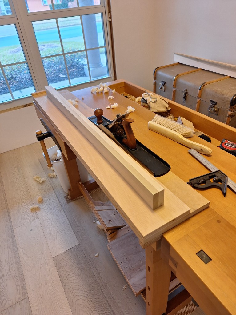
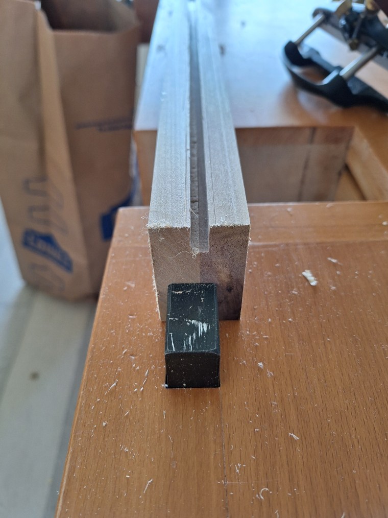
Since I didn’t have a jointer, I used my jointer hand plane to flatten the reference face and reference edge of each board. Here is the first stile I worked on.

First Stile Face and Edge Jointed

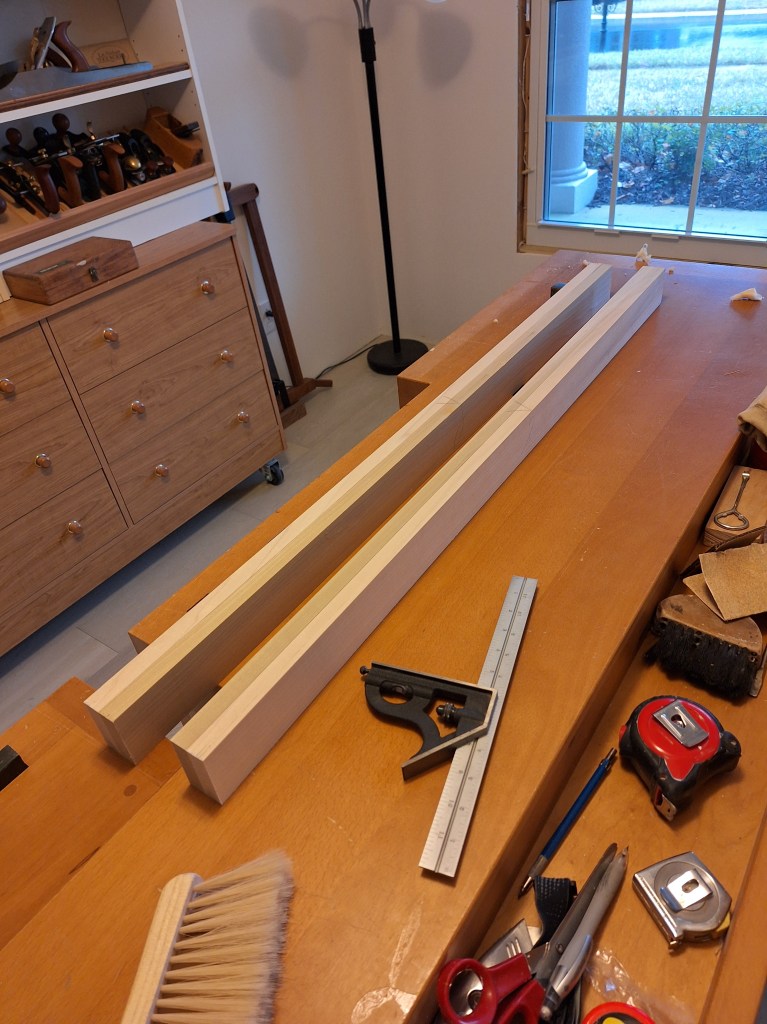
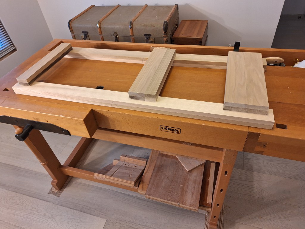
After establishing a reference face and edge, I took it into the garage and used my thickness planer to flatten the opposite face, then pushed it through my table saw to create a parallel edge. Here are the two stiles after both were squared in this manner.

Stiles Squared

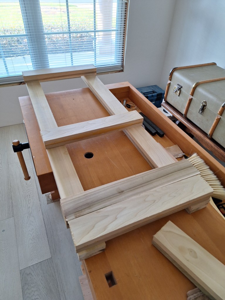
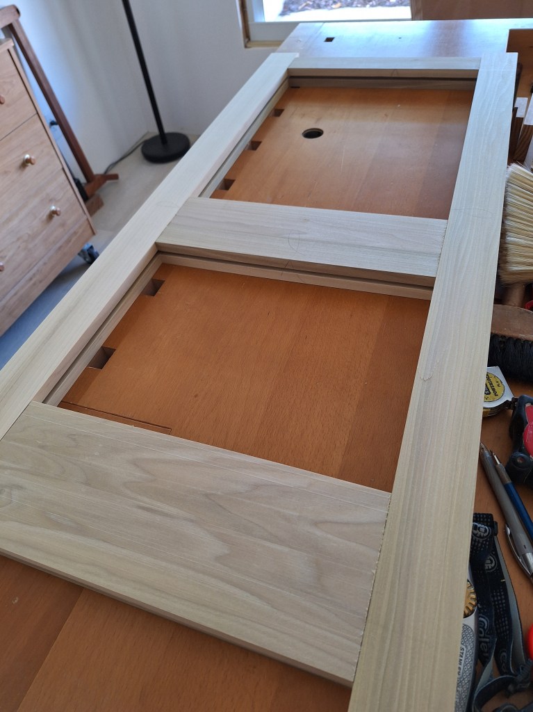
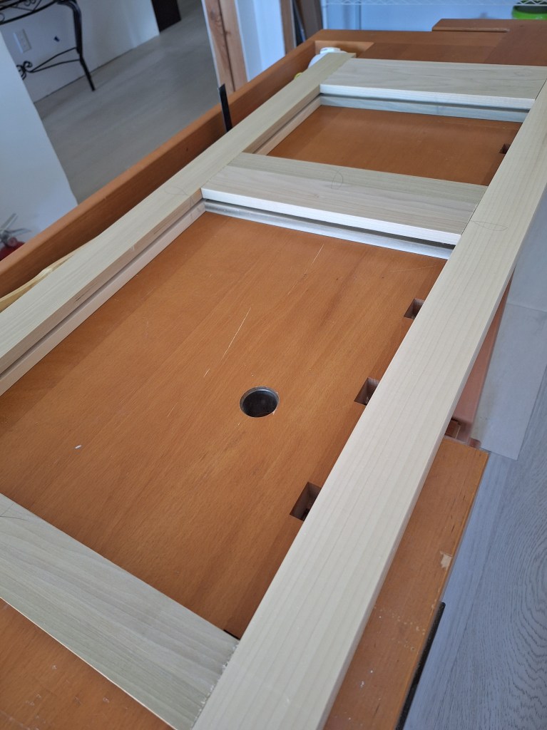
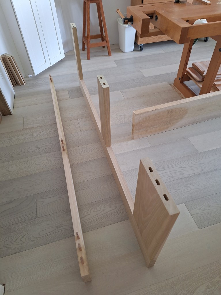
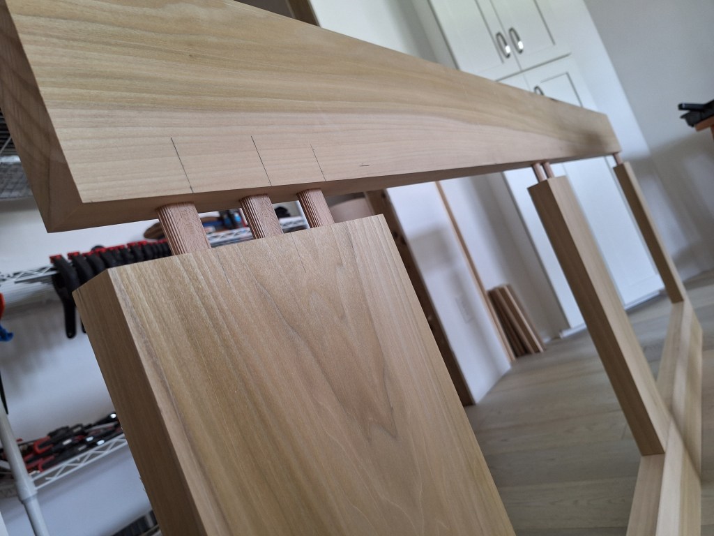
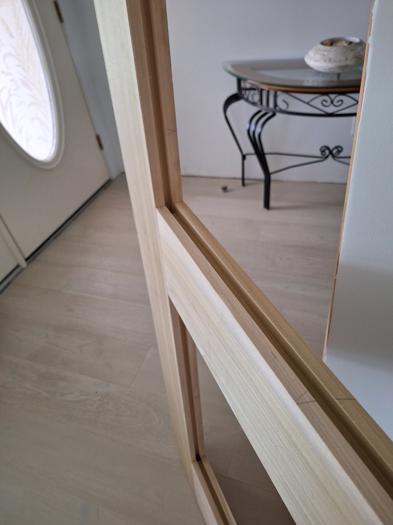
I followed the same process for the rails. Below I am showing them in their approximate position. The width of this prototype door will be 16-1/2″, so I made the rails 14″ long. The rails will be joined to the stiles using mortise and tenon joinery, so the tenons will extend into the stiles, which is why they sit on top of the stiles as shown below. Also note that the stiles will have an extra inch at either end (top and bottom), which is needed to provide extra support as I cut the mortises at each end of the stiles. This extra length will be cut off after the rails area joined to the stiles.

Rails and Stiles Squared

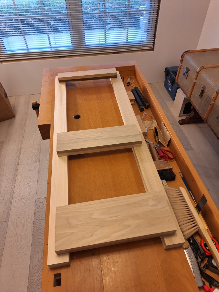
These boards are now ready for the joinery phase. At this stage I hadn’t decided on the material nor type of panel I would make, but this would not impact the cutting of the grooves that will receive the panels. The edges of the panels will be inserted into 1/4″ wide grooves along the stiles and rails, each with a depth of 1/2″. I used a plough plane for this and started with the top rail.

Cutting the Groove for the Top Rail

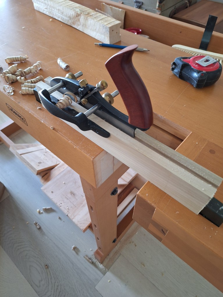
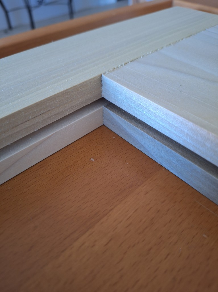
Below I show the same rail being cut, but from the end, where the full depth has not yet been reached. The score lines you see on either side of the groove were the result of an experiment to help prevent tear-out. I won’t get into it, but it turned out not to be necessary, so this was the only place where you’ll see such lines.

Edge View of Top Rail Groove being Cut

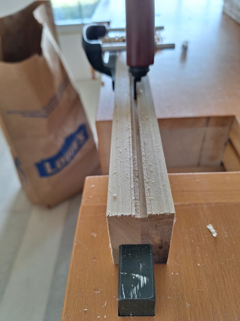
Below I show the top rail with the groove cut to full depth.

Edge View of Top Rail Cut to Full Depth

I did the same for the remaining rails and the stiles. The lock rail (middle one) required a groove on both edges since it will receive a panel from above and below.

All Grooves Cut – bottom to top.
All Grooves Cut – top to bottom.
Closeup of the Bottom Rail meeting a Stile

The next step was to cut the mortises in the stiles that will receive the tenons (which will be cut in the rails). I’ve cut mortises by hand before and found it very labor intensive, but thought I’d give it another try. Although I was happy with the mortise I cut, it was just too impractical to be doing this by hand, especially given the number of doors I plan to make. So that operation, along with the many others, led me to abandon the idea of making the doors primarily with hand tools. Instead, would switch to using machines.

This change in approach meant that I had to purchase a number of tools that would make the job more manageable. It would be a significant investment, so a lot of time and thought went into what would make the most sense. For the joinery I would use the Festool Domino. It cuts a mortise in both pieces being joined and uses a “loose” tenon to bring them together. This will be seen later. I would also introduce a jointer for milling, and other machines that too will be revealed later.

After deciding what tools I would get and ordering them, it would take quite some time for a few of them to arrive. So the prototype door was put on hold as I began preparing my garage shop for the new equipment. One thing I was able to do in the meantime was pickup the 8/4 poplar that I would use for the real door.

8/4 Poplar Boards

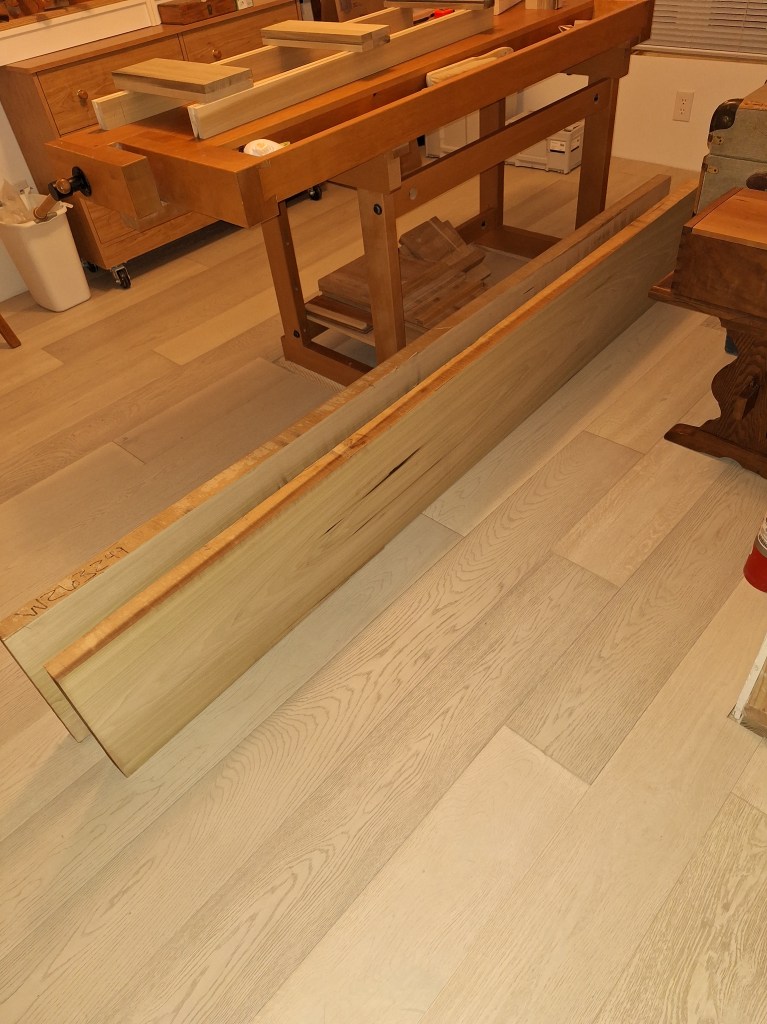
The two boards shown above were actually part of one 16 foot board that was cut in half for me to fit in my car. They are 13 1/2″ wide, so pretty beefy. It took a bit of hunting to find a supplier for these boards, so I was happy to get them and bring them into my house where they acclimated for some time before I started working with them. They are kiln dried, but it’s always a good idea to let them settle in their destination environment for several weeks (if not more).

I took one of them into the garage and ripped it down the center with a hand saw. These two pieces will be the stiles.

Ripping the Stiles by hand.
Stiles Ripped

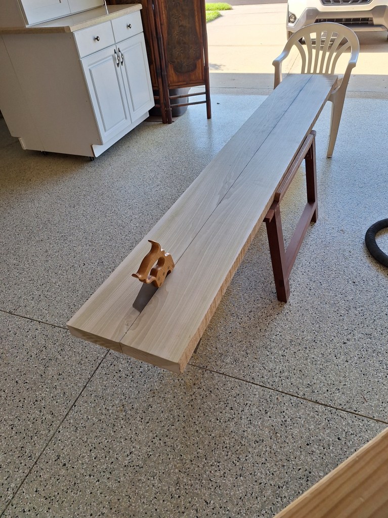
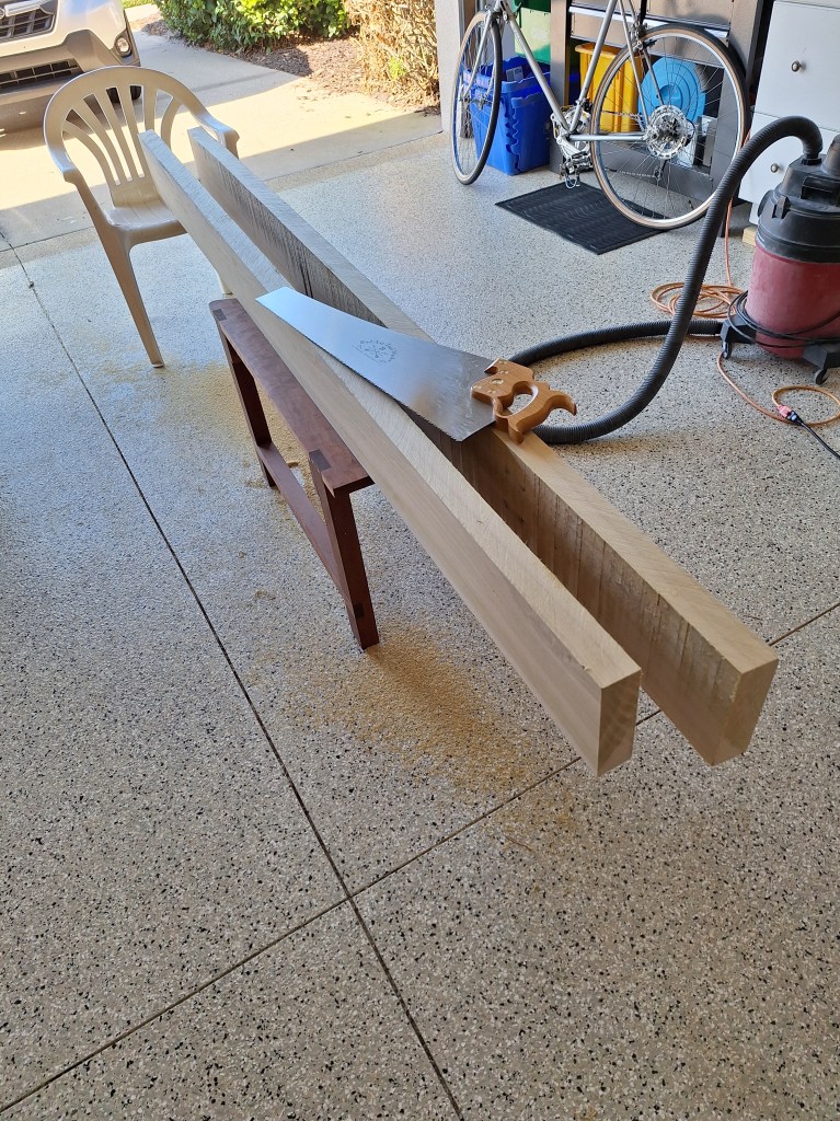
Hand cutting this board was actually quite enjoyable. I have a really good rip saw, so I took my time and let the saw do most of the work. I achieved a nice straight cut. In future I will probably do this with a track saw, but at the time of writing this, I hadn’t made that decision. These two pieces were returned to the workshop inside the house where they would sit for several weeks as I waited for the new equipment to arrive.

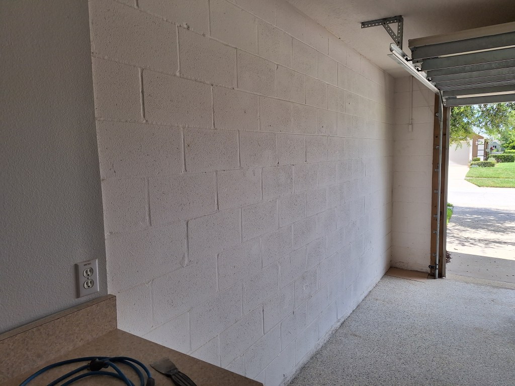
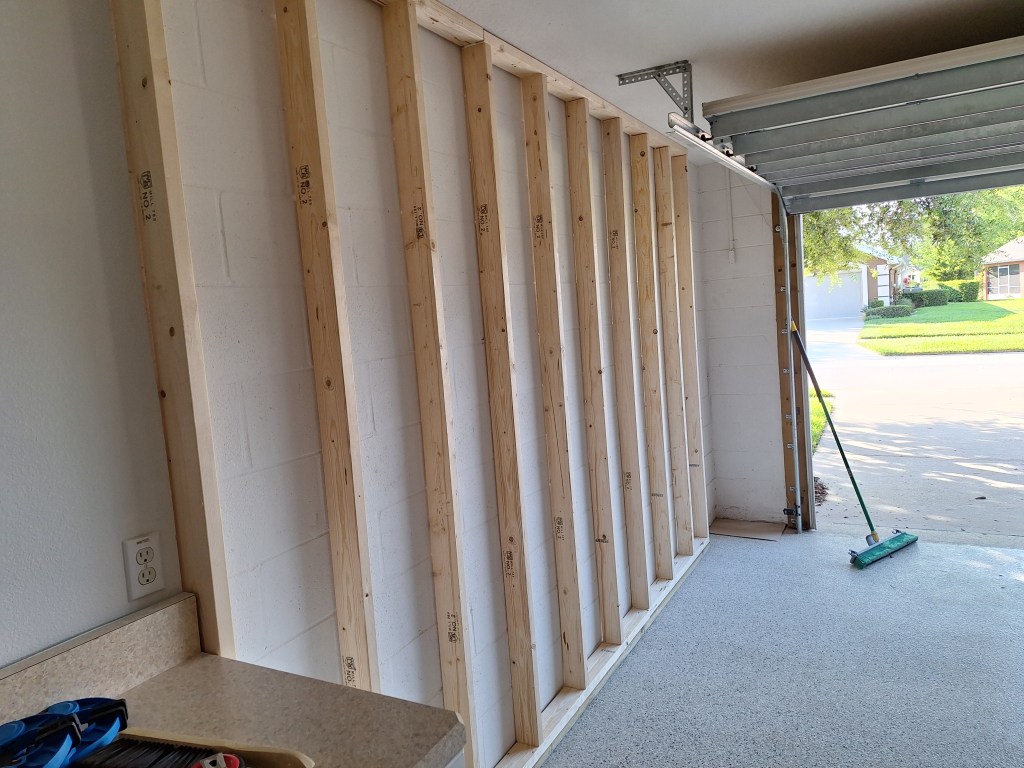
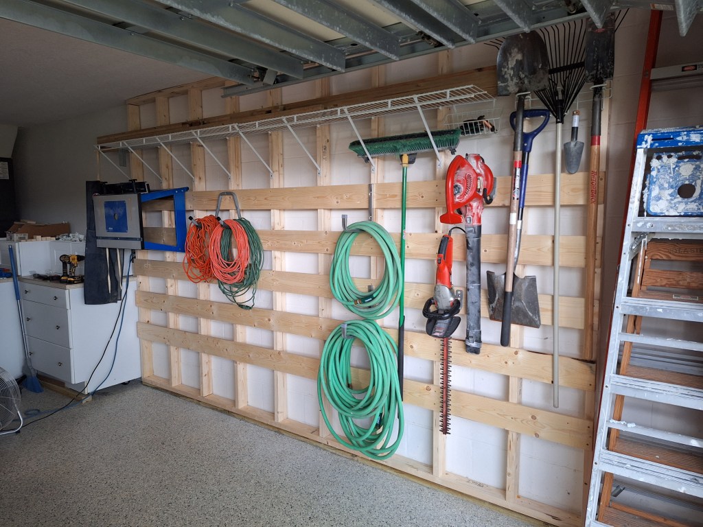
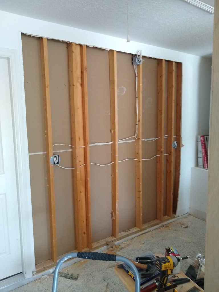
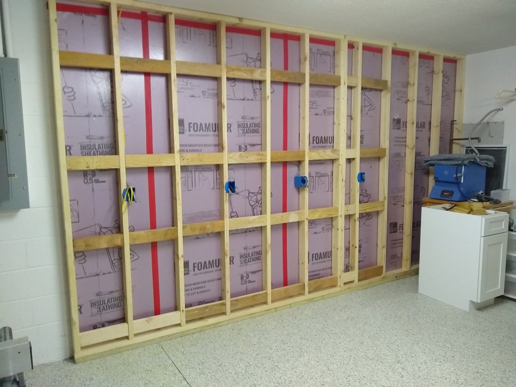
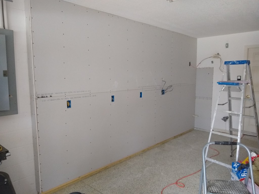
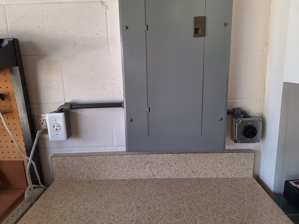
One of the new pieces of equipment would be an 8″ jointer, which requires a 240 volt outlet, so I had one added. I wimped out on this and simply hired an electrician to do it. He arrived the same day and knocked it out very quickly. Although expensive, I was happy to have that done.

240 Volt, 20 Amp Outlet

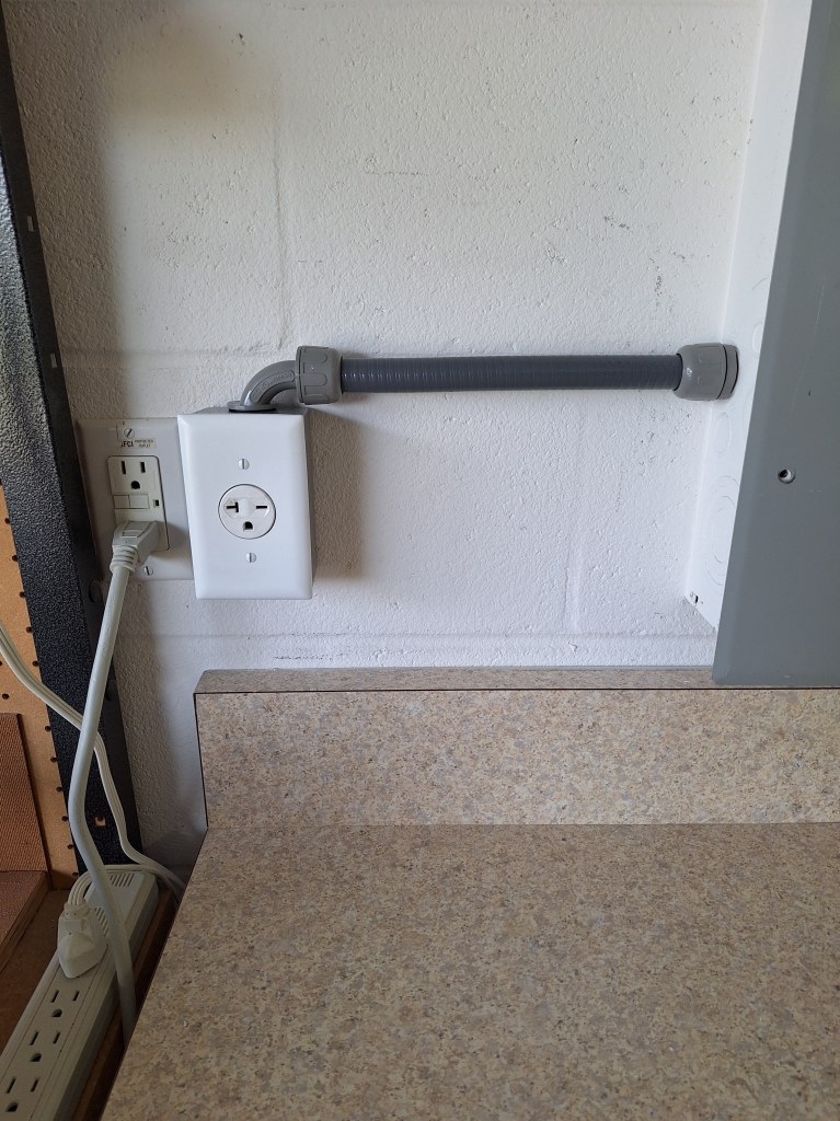
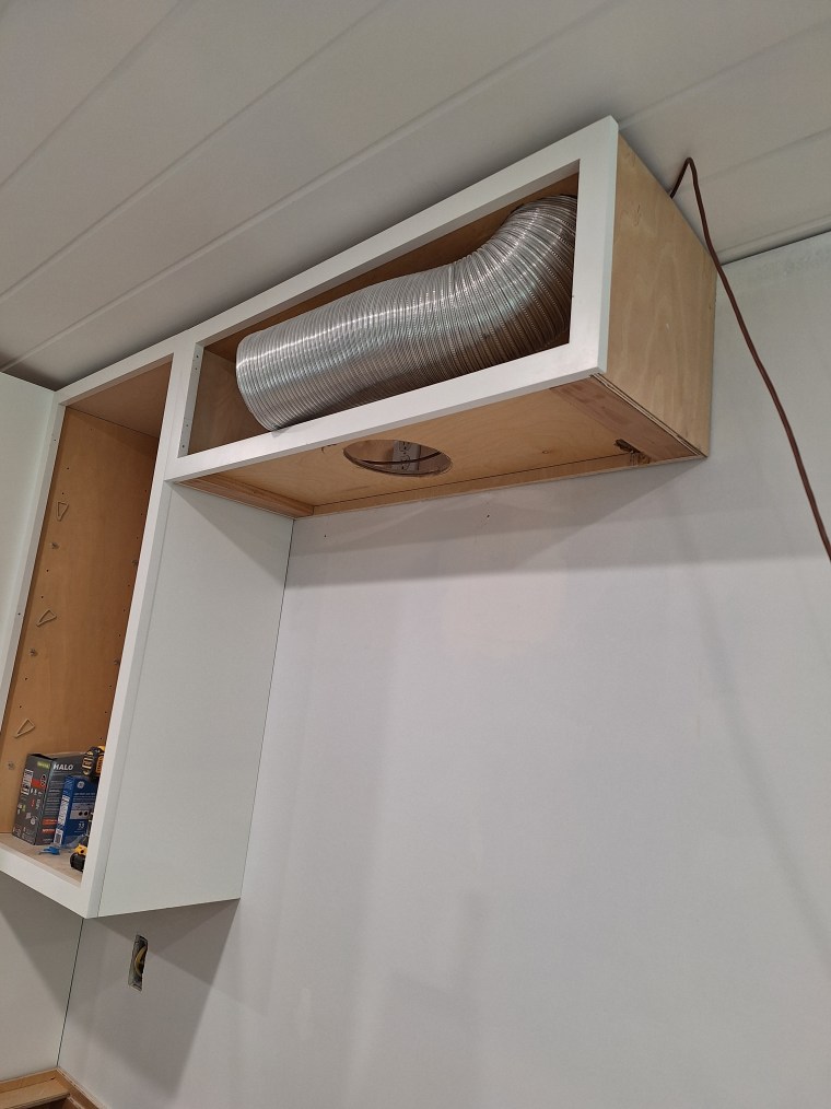
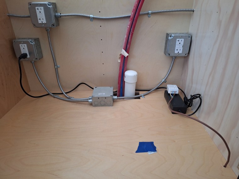
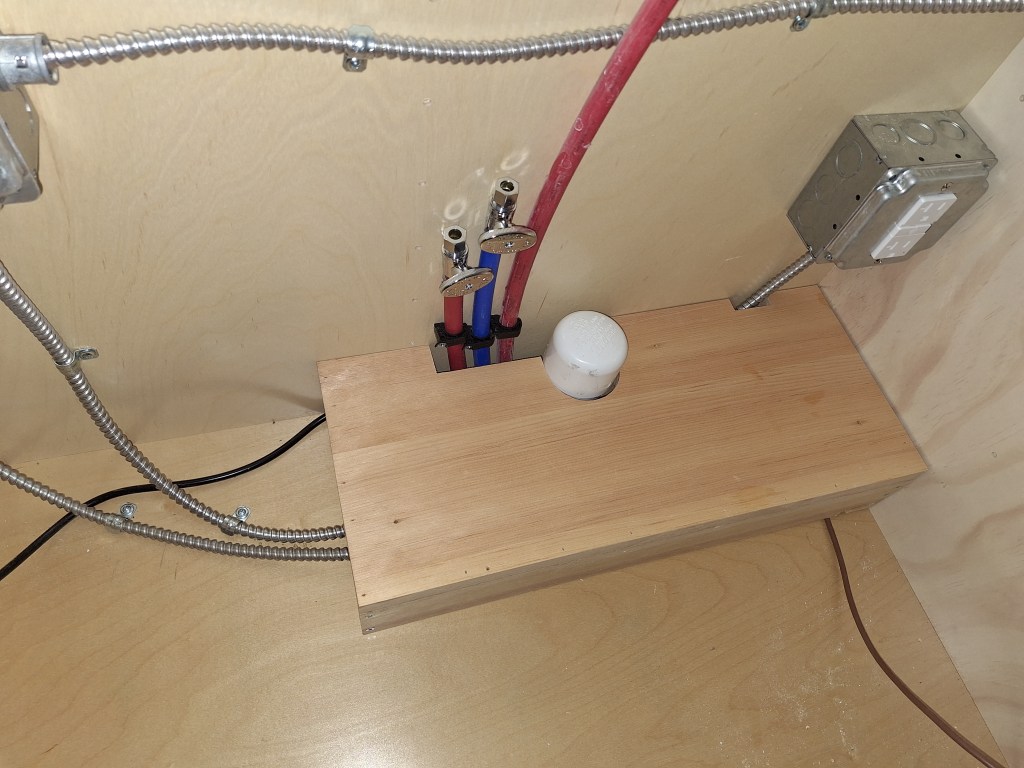
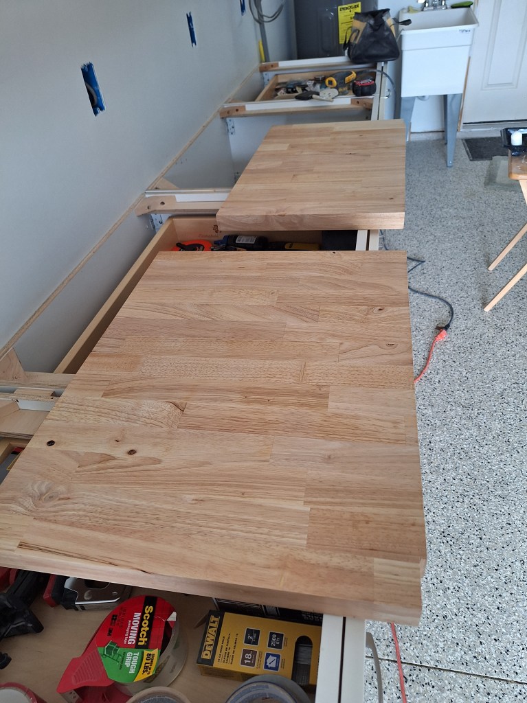
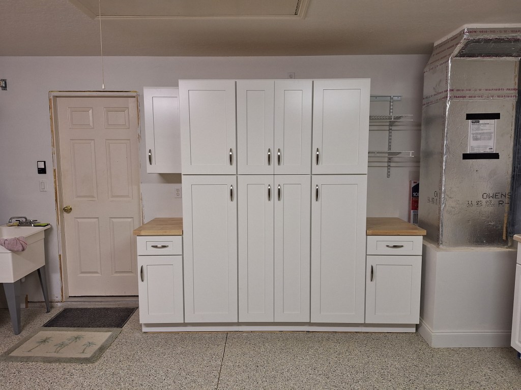
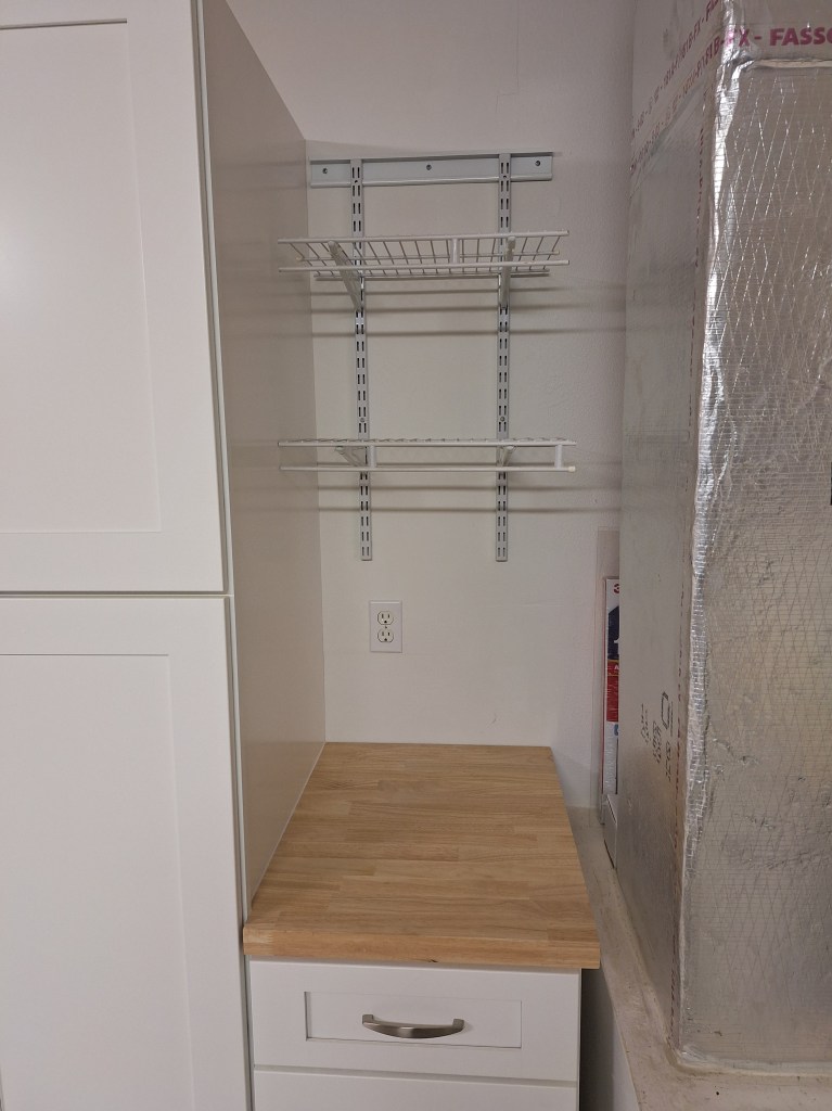
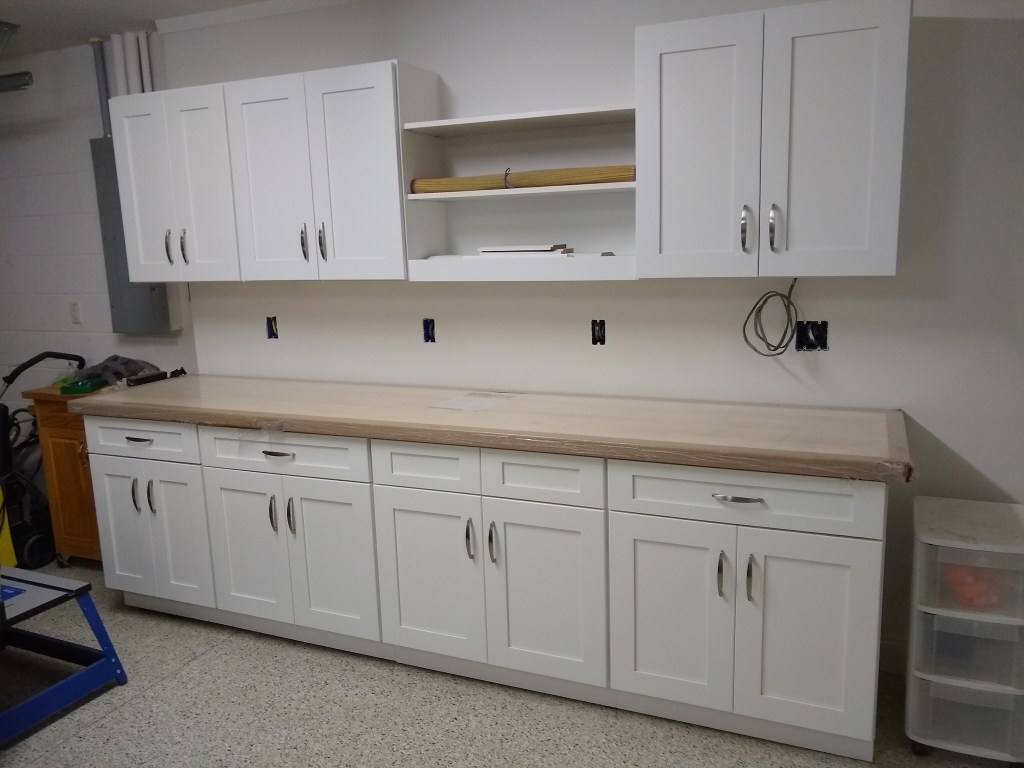
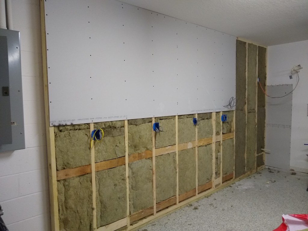
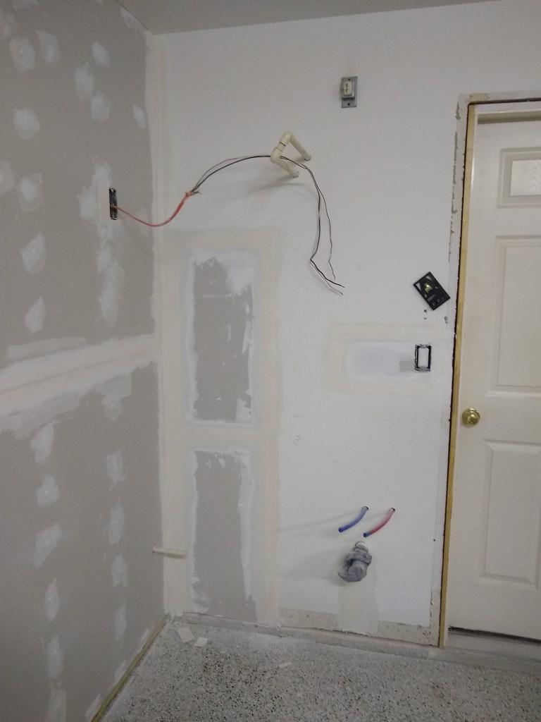
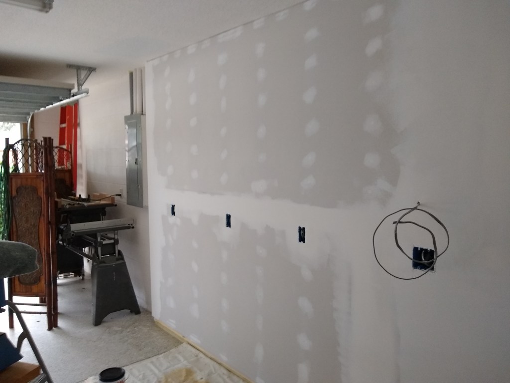
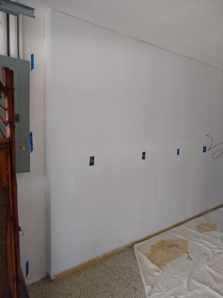
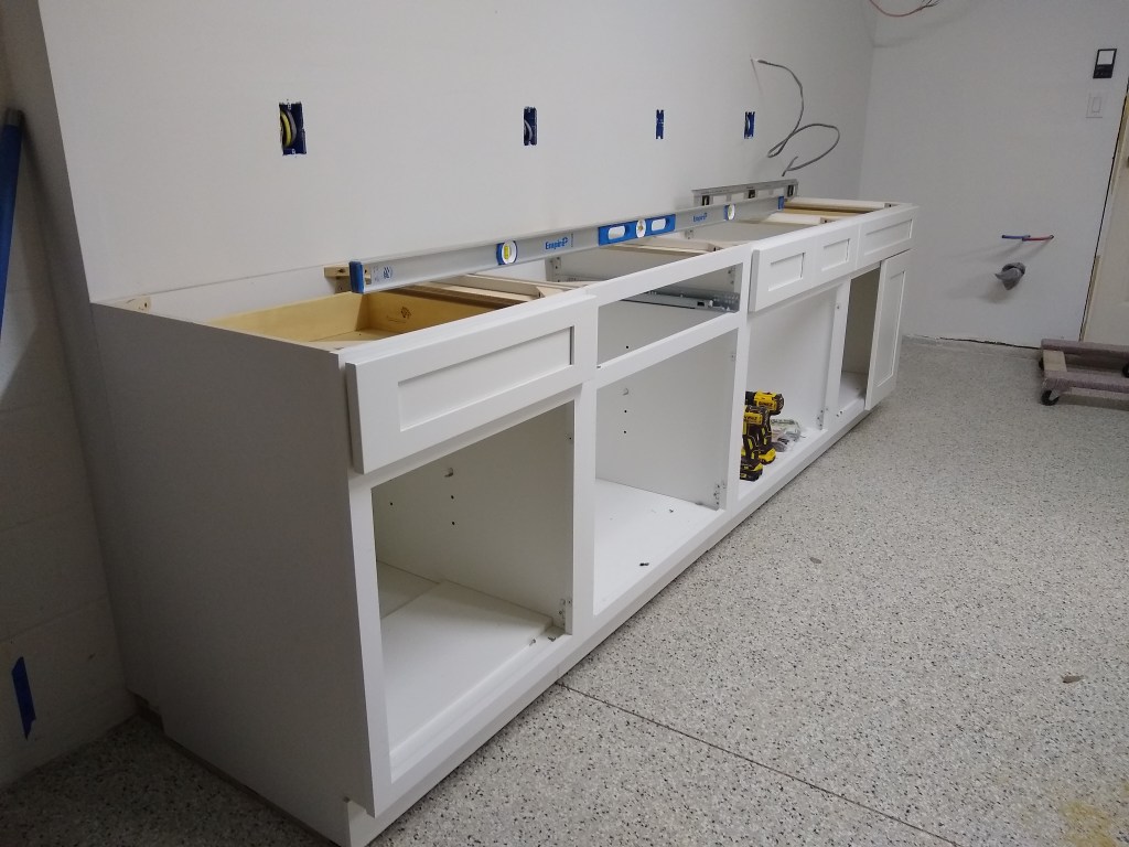
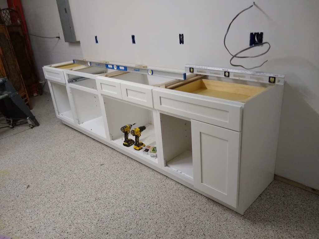
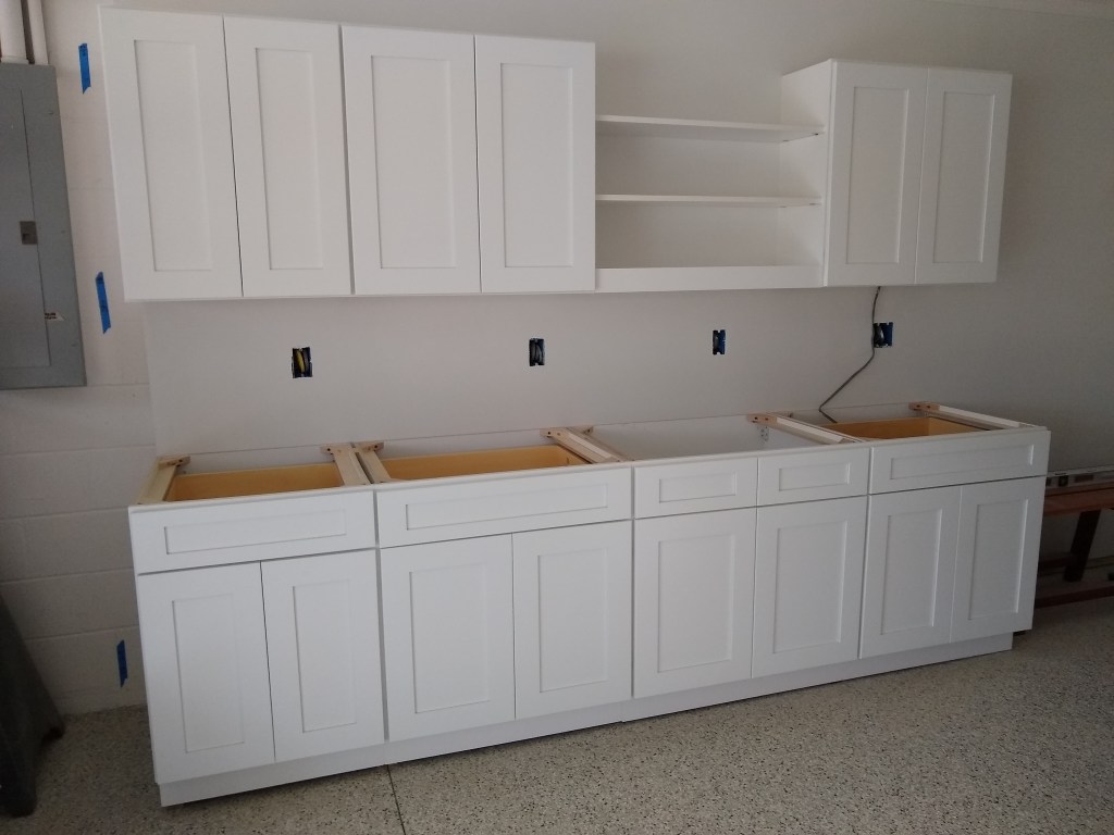
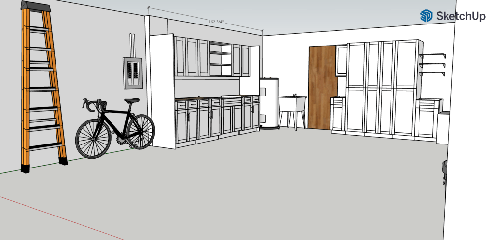
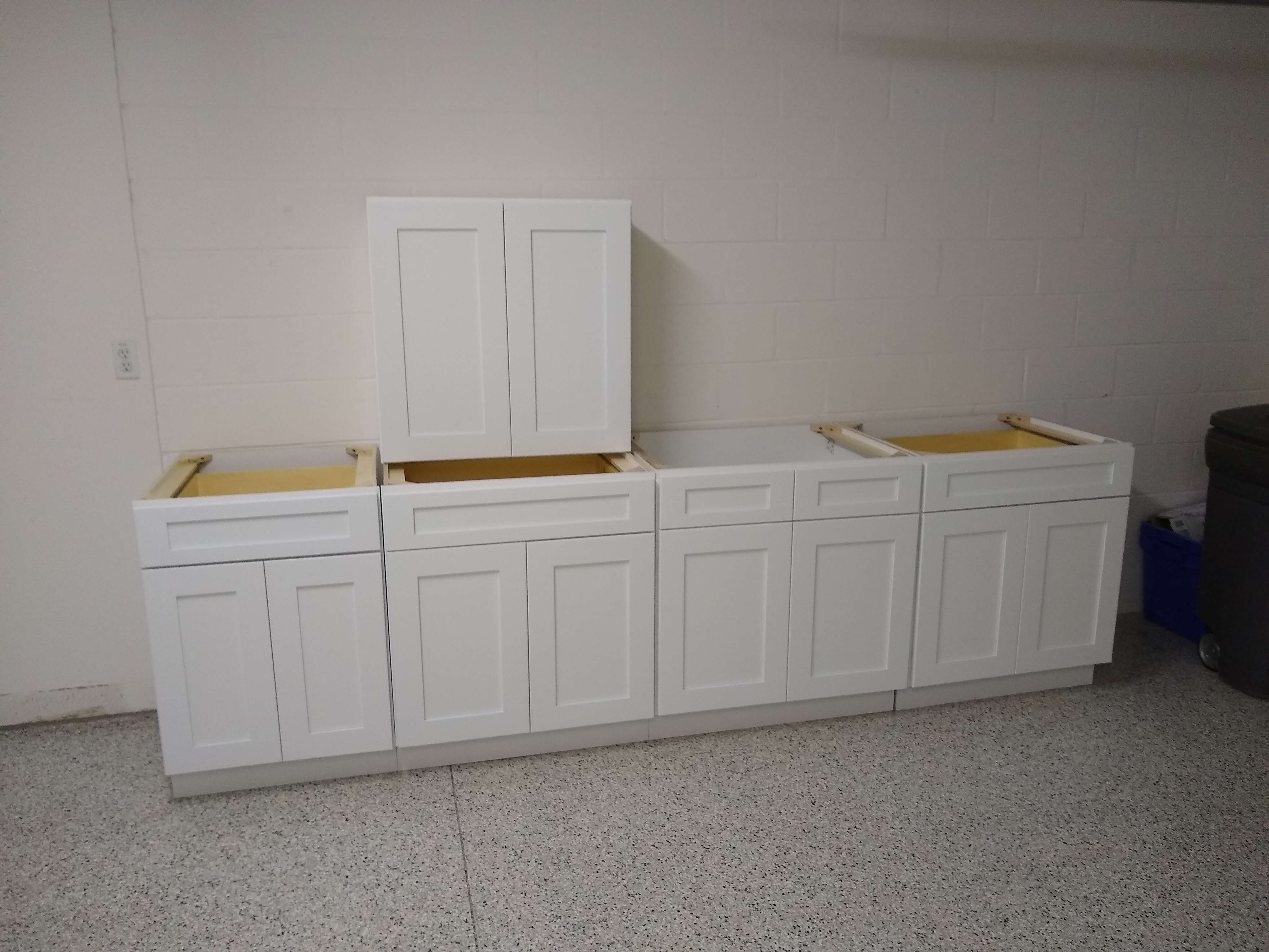
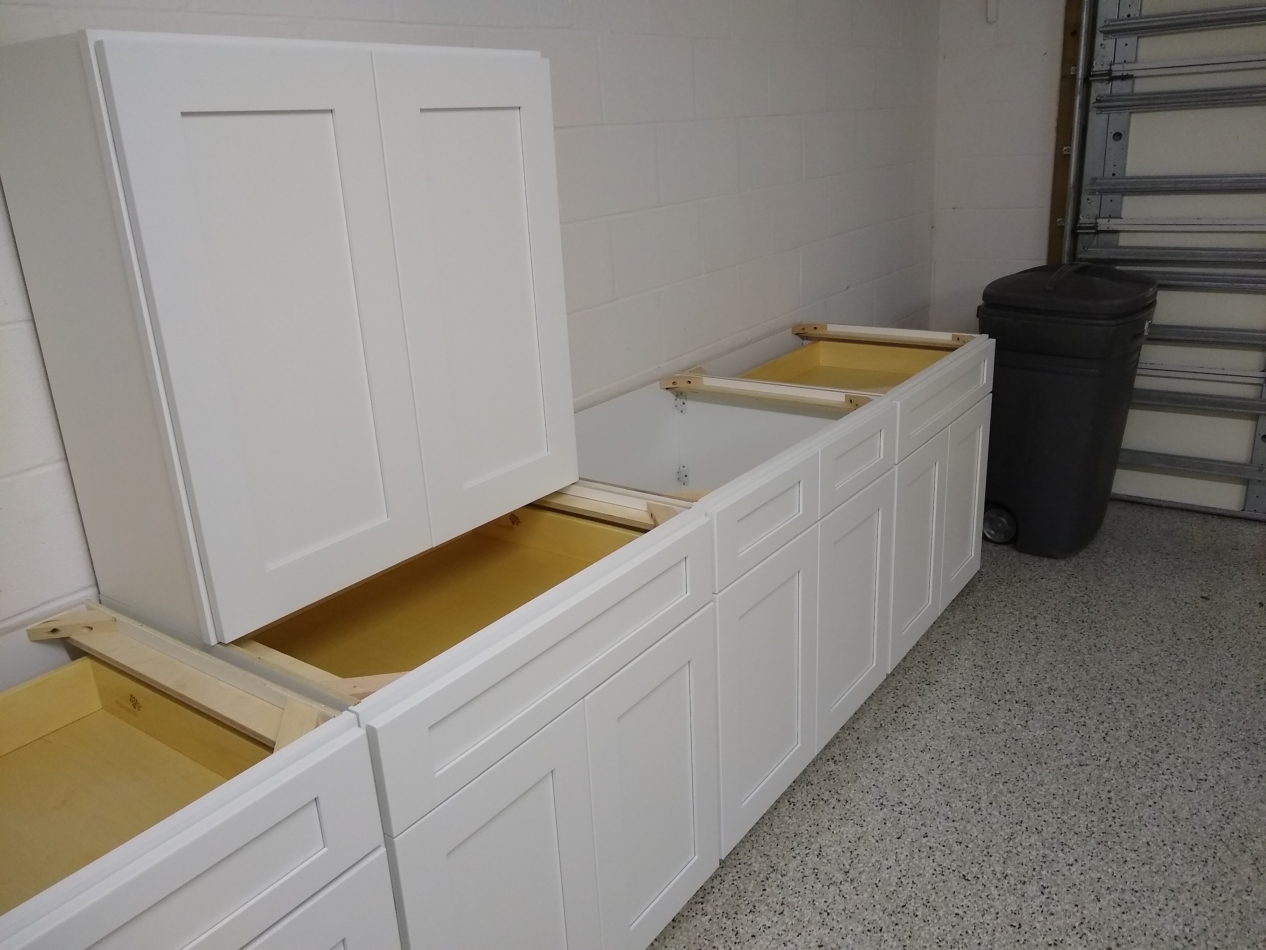
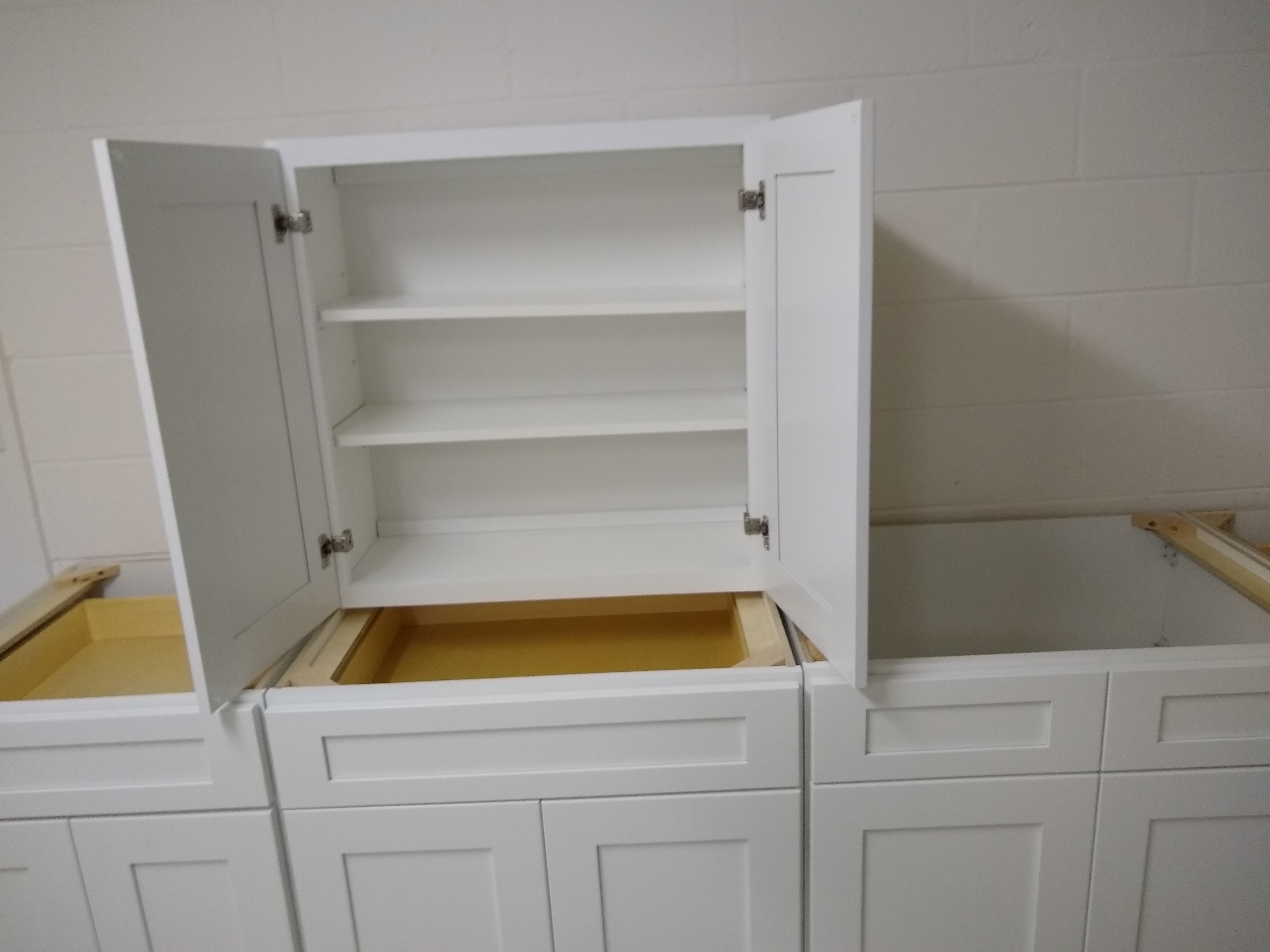
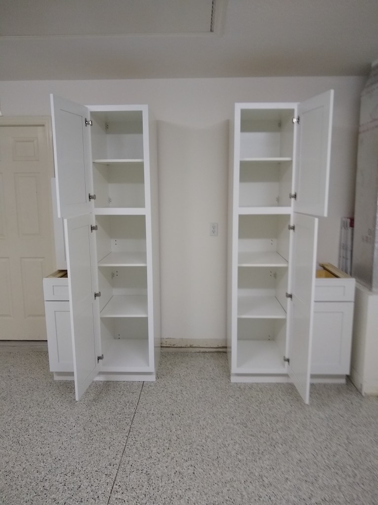
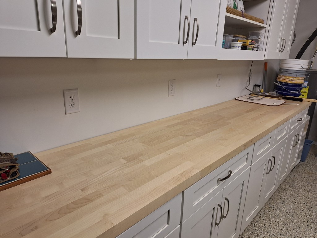
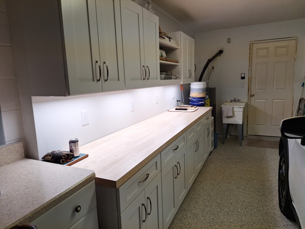
Along that same wall and under the cabinets are four 120 volt outlet boxes I added way back. I held off on installing the outlets because I intended to add some kind of backsplash first. These are connected to a 20 amp circuit. The other outlets in the garage are on a 15 amp circuit, so these will provide plenty of juice for some of the new equipment (e.g., the new dust collector will need one of these). Even though I hadn’t done anything about the backsplash, these outlets would be needed, so I decided to install them ahead of that.

Wiring the 20 amp Outlets
20 amp Outlets Installed

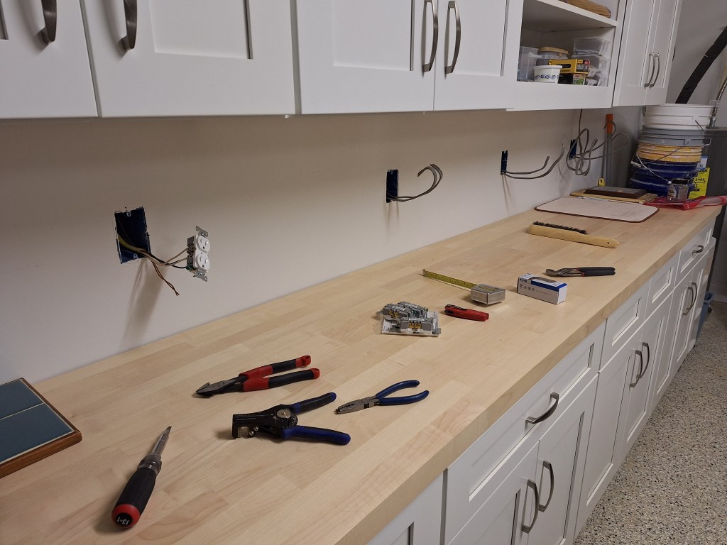
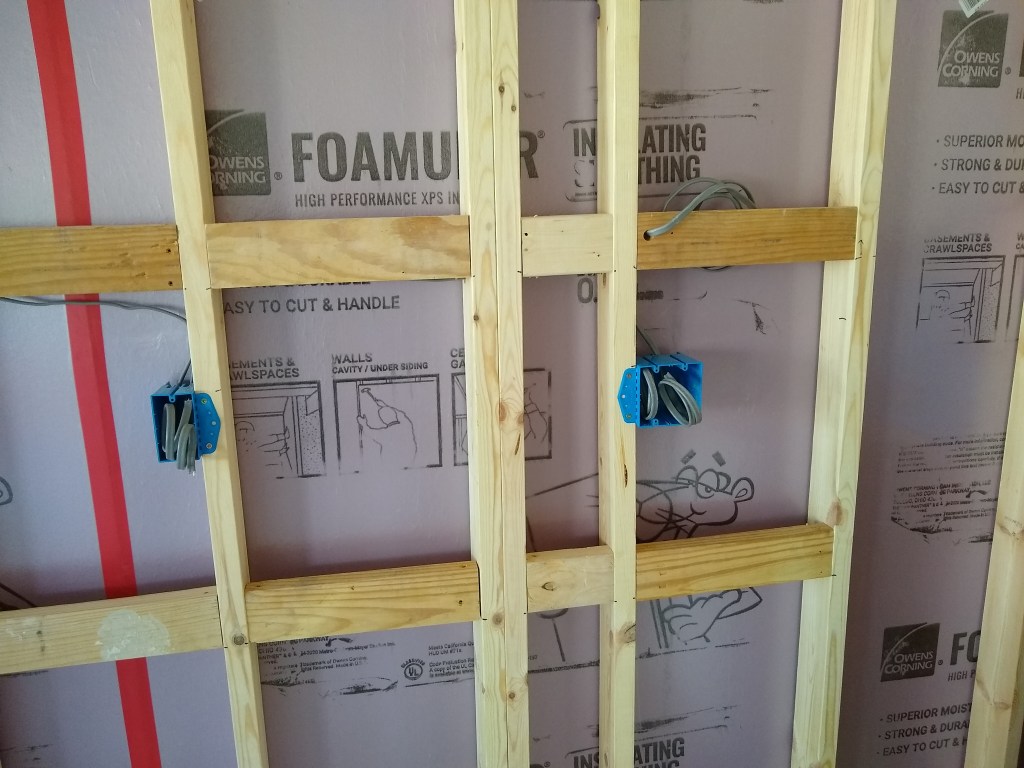
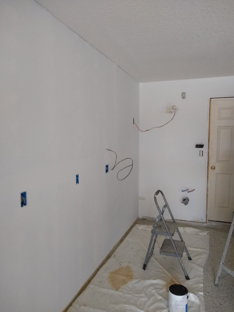
The wire you see hanging at the end is for the under-cabinet lighting. Here is a closeup of that situation.

20 amp Outlet and Switch

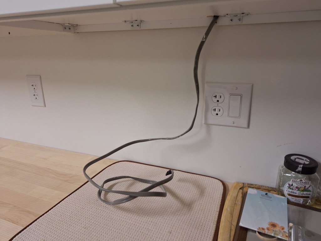
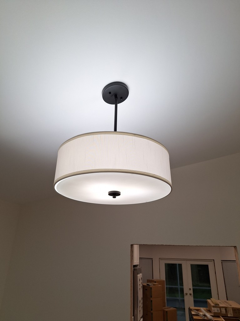
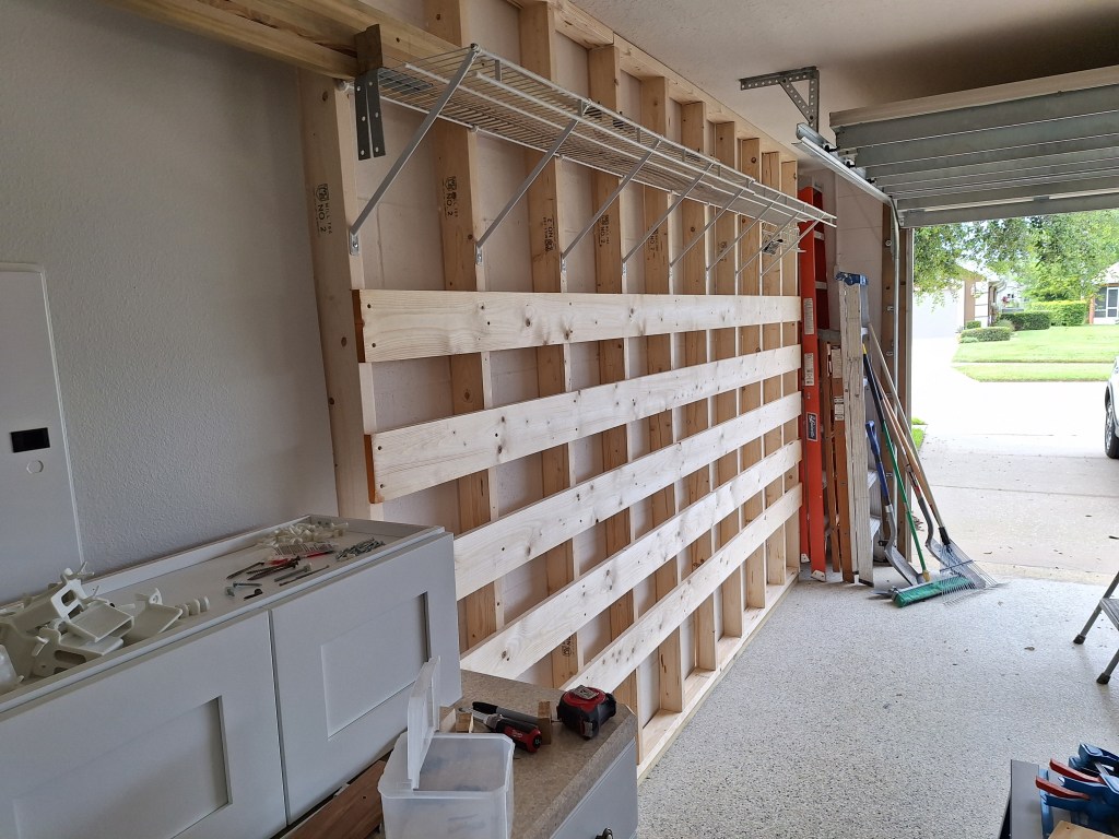
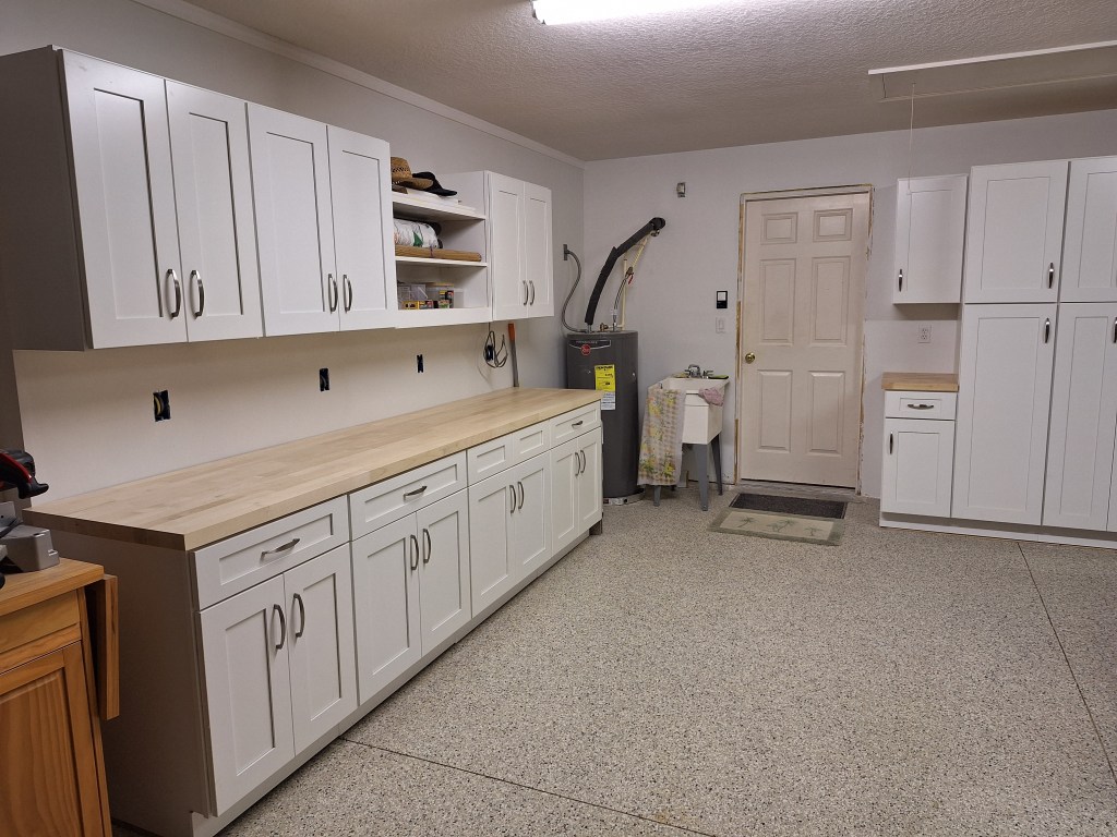
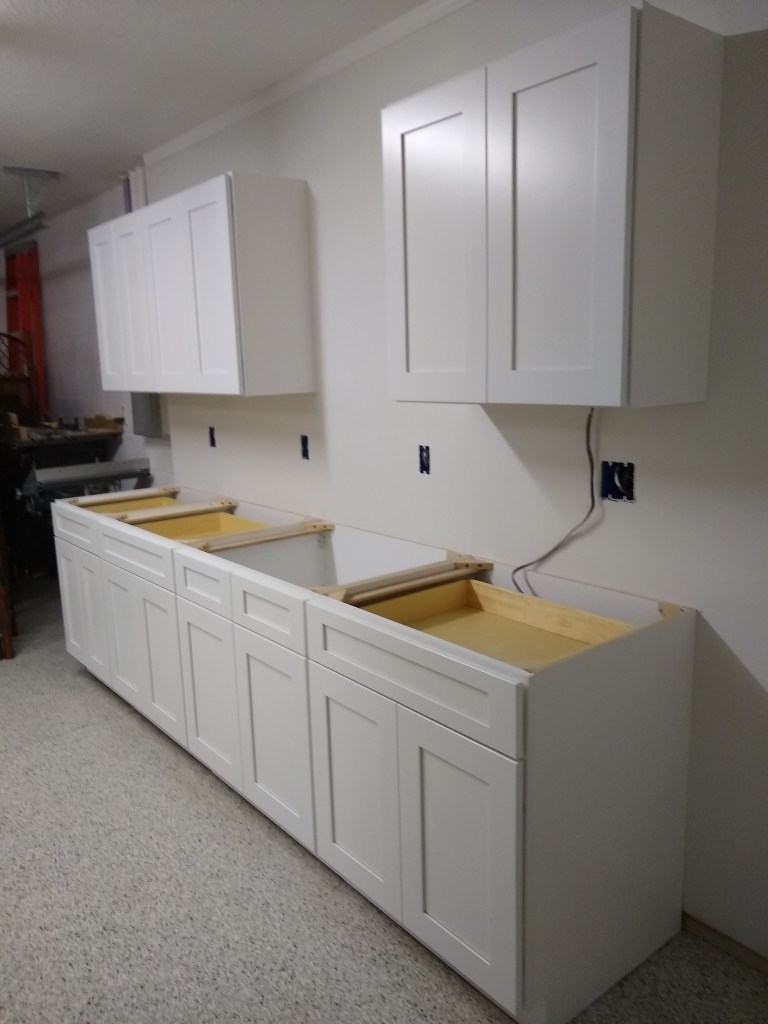
The switch you see in the image above will send current to the wire you see hanging. It will connect to a series of under-cabinet lights. I picked them up a few days later and installed them, as seen below.

Under Cabinet Lights Installed

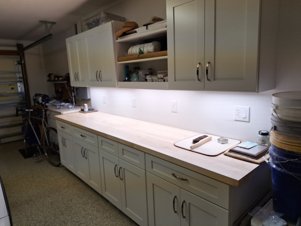
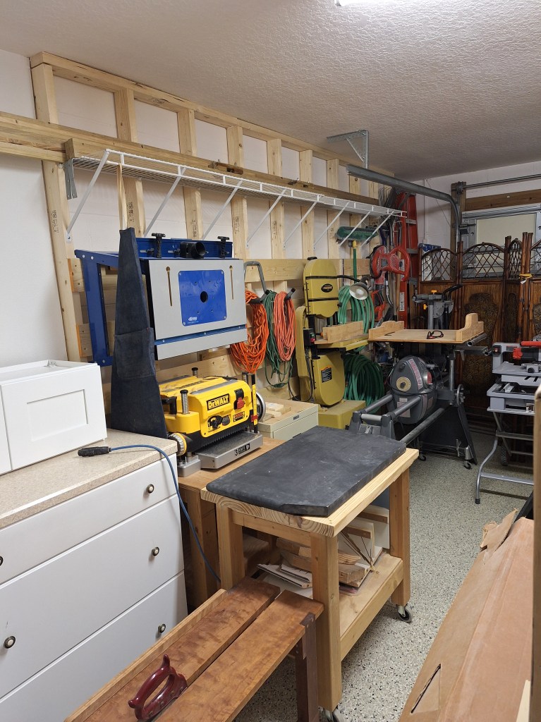
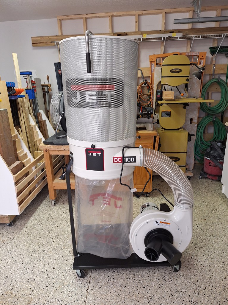
I’m very happy with the under cabinet lights. I made use of them as I was read the instructions for how to assemble my new Jet DC-1100vx dust collector, which arrived during that time.

New Dust Collector

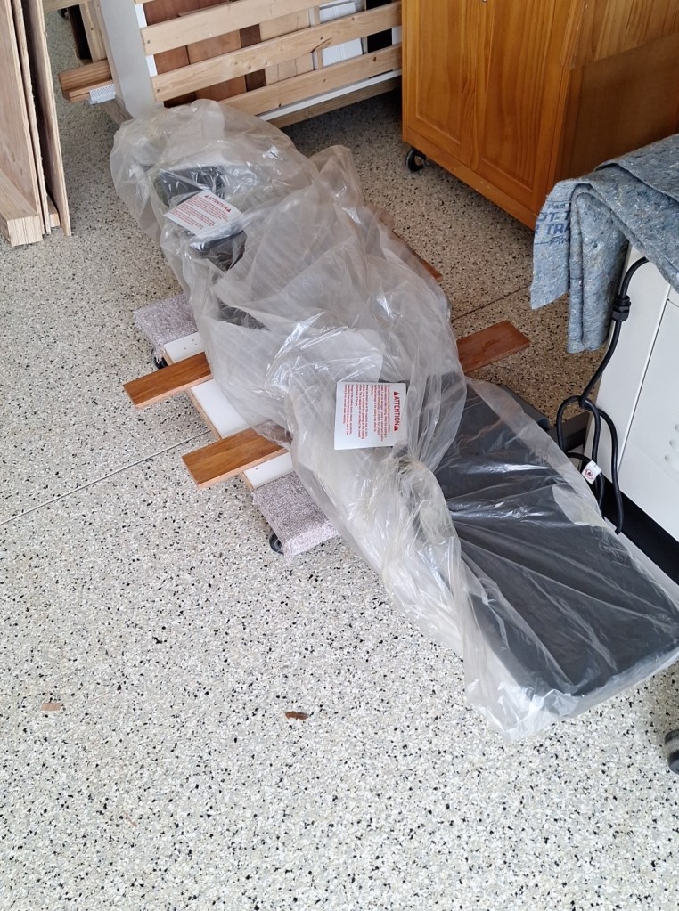
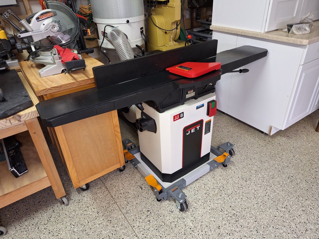
I also ordered a Jet Black 8″ helical head jointer. This is a big machine and would require some assistance getting it to my house and into the garage. It came in two pieces.

Jointer Head
Jointer Stand – after I set it on a Mobile Base

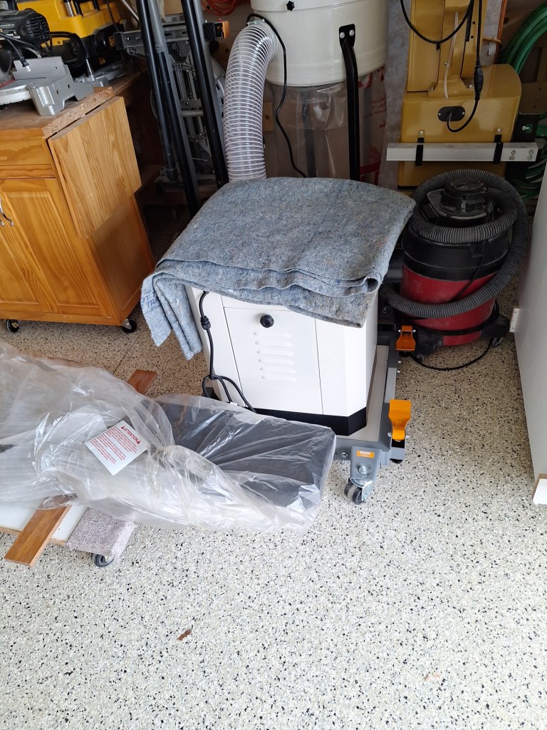
Since I always want to be able to pull my car into the garage, tools must be mobile, so the jointer base was placed on a mobile base, which I purchased separately. Then came the tricky part; getting the 300 lb head onto the base. My neighbor, Fred, came over to help with that. Below I show it after the head was mounted and the remaining bits and pieces were attached.

Jointer Assembled

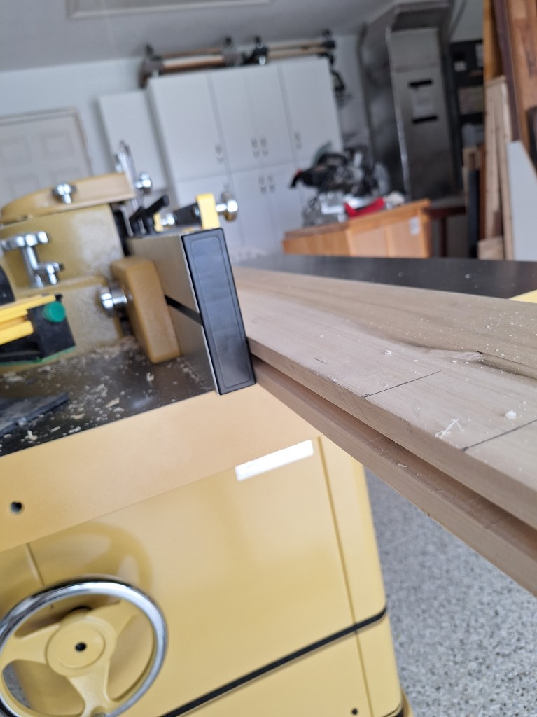
To try it out, I hooked up the dust collector and ran a scrap piece of cherry through it. First I flattened a face, then used that face to register against the fence to produce a 90 degree edge.

Jointing Test Board Face
Jointing Test Board Edge

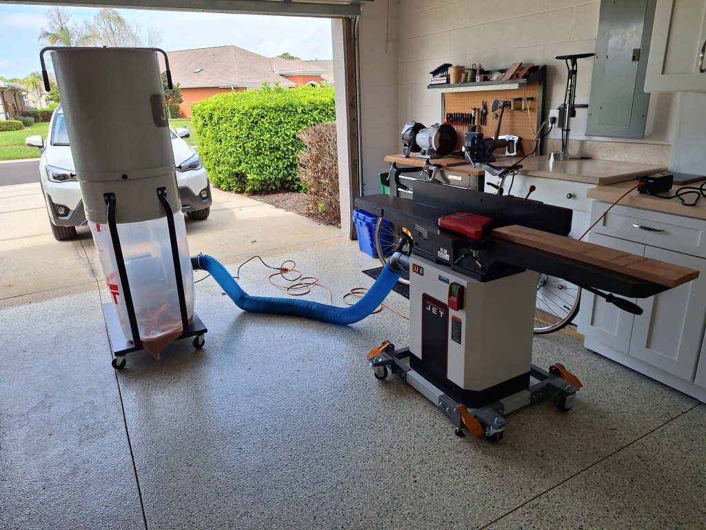
It worked beautifully, as did the dust collection. I was very happy with the results, so it was time to use it on the real thing.

Full Scale Stile Face and Edge Jointed

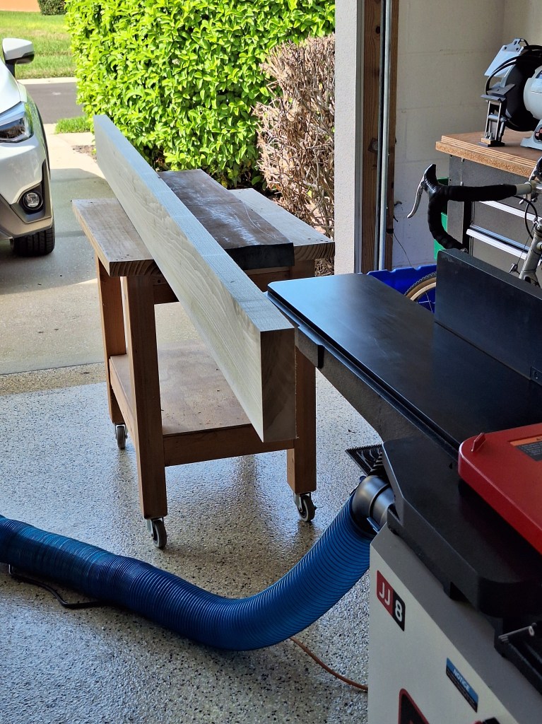
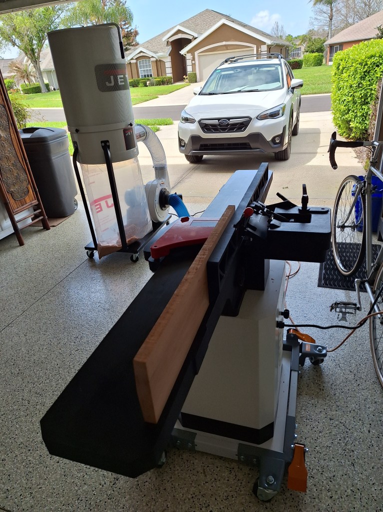
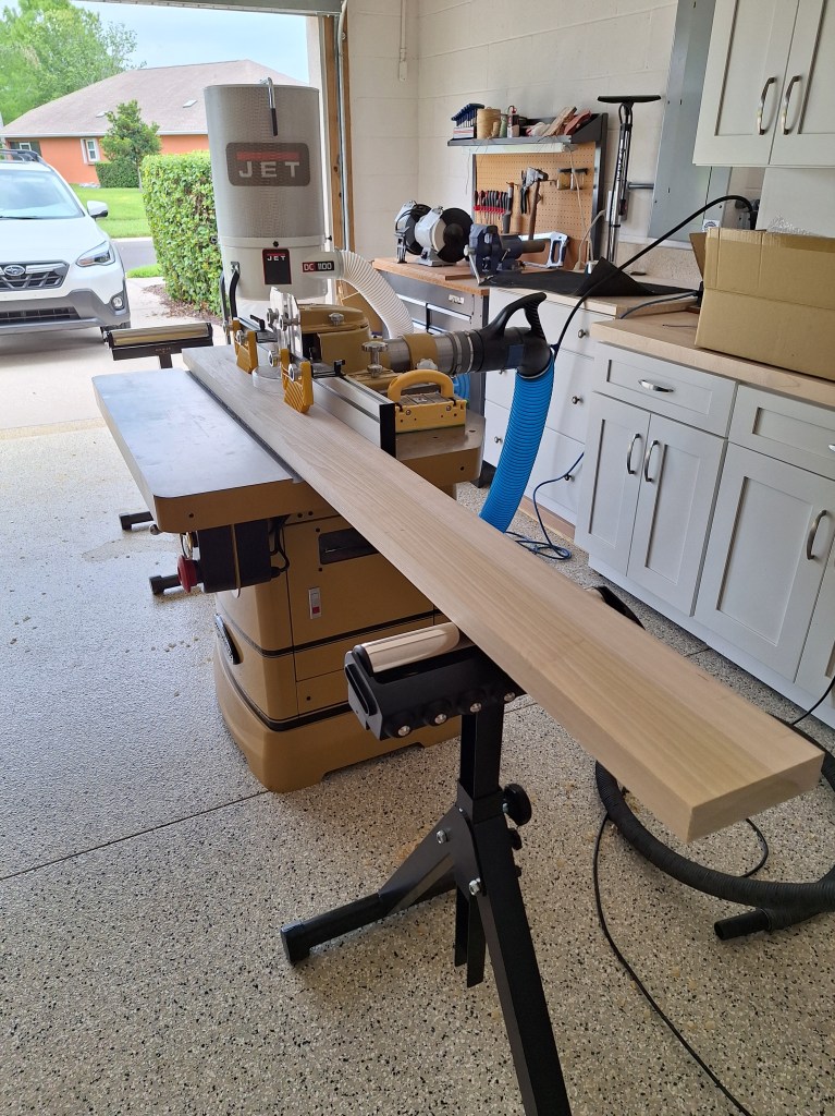
Except for the lack of proper infeed/outfeed support, jointing this 8 foot long 8/4 board was a breeze. I improvised an outfeed table, as shown above. Although it worked, it became clear that a couple of adjustable roller supports would be needed, which I subsequently purchased. With them, I was able to mill all the stiles and rails for the full size door.

Stiles and Rails Milled

I hadn’t abandoned the prototype door. Although I had cut the grooves by hand, I would be switching to using a router for the full size doors, and the motor I ordered would not be arriving for some time. Once it arrived, I intended to try it out on the prototype door, expanding the size of the groove to match that of the full sized door. That would mean that the prototype would no longer be strictly 1/2 scale. Although the dimensions would not be accurate, it would be more important for me to practice the joinery before committing to the real thing.

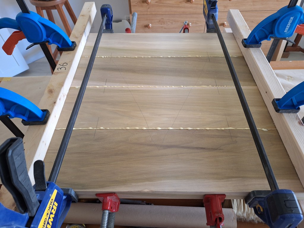
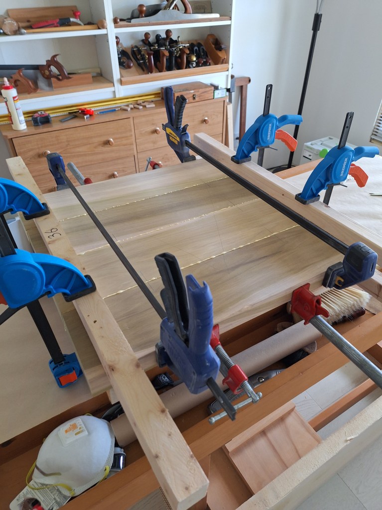
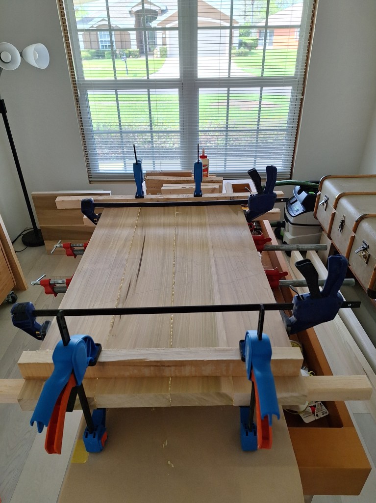
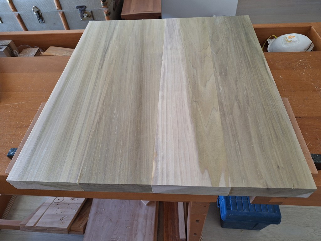
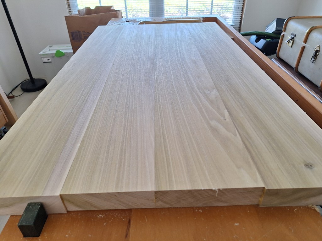
While waiting for the router motor I milled the wood that would make up the top and bottom panels. Once milled, they were glued together, as shown below. Although not strictly necessary, I used Dominos to join the panel pieces because they would aid with alignment. With such beefy pieces, the Dominos kept the pieces from sliding around as the clamps pulled them together.

Bottom Panel Glue Up
Top Panel Glue Up
Top Panel Glue Up

Once out of the clamps I used my No. 7 jointer plane to flatten both panels.

Bottom Panel Hand Planed
Top Panel Hand Planed

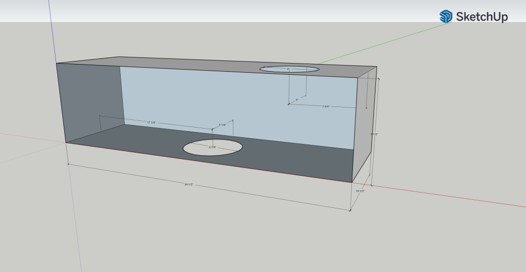
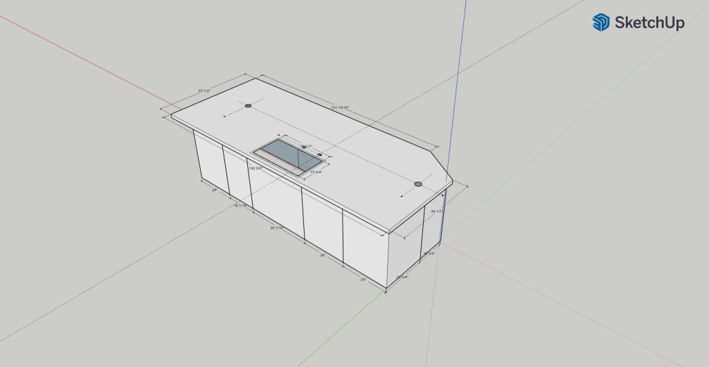
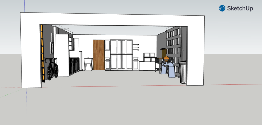
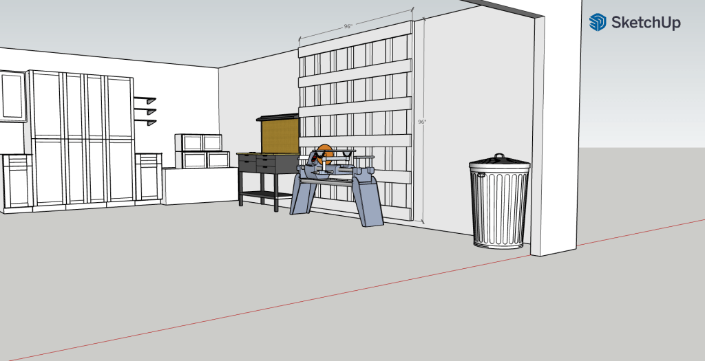
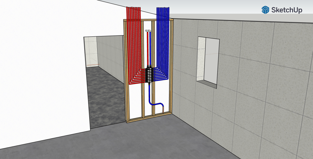
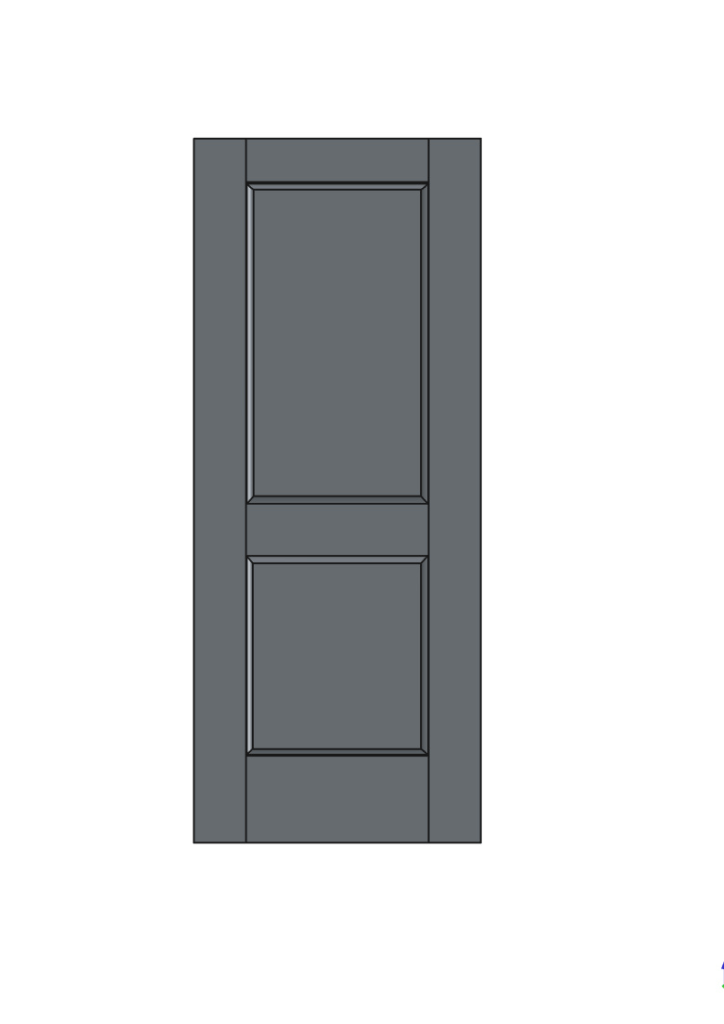
While still waiting on the router motor, I decided to use FreeCAD 3-D modeling software to create a 3-D model of the door. By creating a 3-D model I could get a sense of the size of the cove I wanted to use to raise the panels. FreeCAD is free software. It is very powerful, but has a steep learning curve. I wanted to become competent with this software so that I could use it to design all of the things I plan to build. Although not strictly required for the doors, I thought it would be a good place to start, since it is a relatively simple thing to model. When I become more capable with FreeCAD, it will be very useful when designing the closet layouts down the road.

3-D Model of Guest Bathroom Door

After completing this 3-D model, my router motor arrived. I mounted it to the router table and modified a mobile bench I had to set the router table on. It all looked very good.

Router Table on Mobile Base

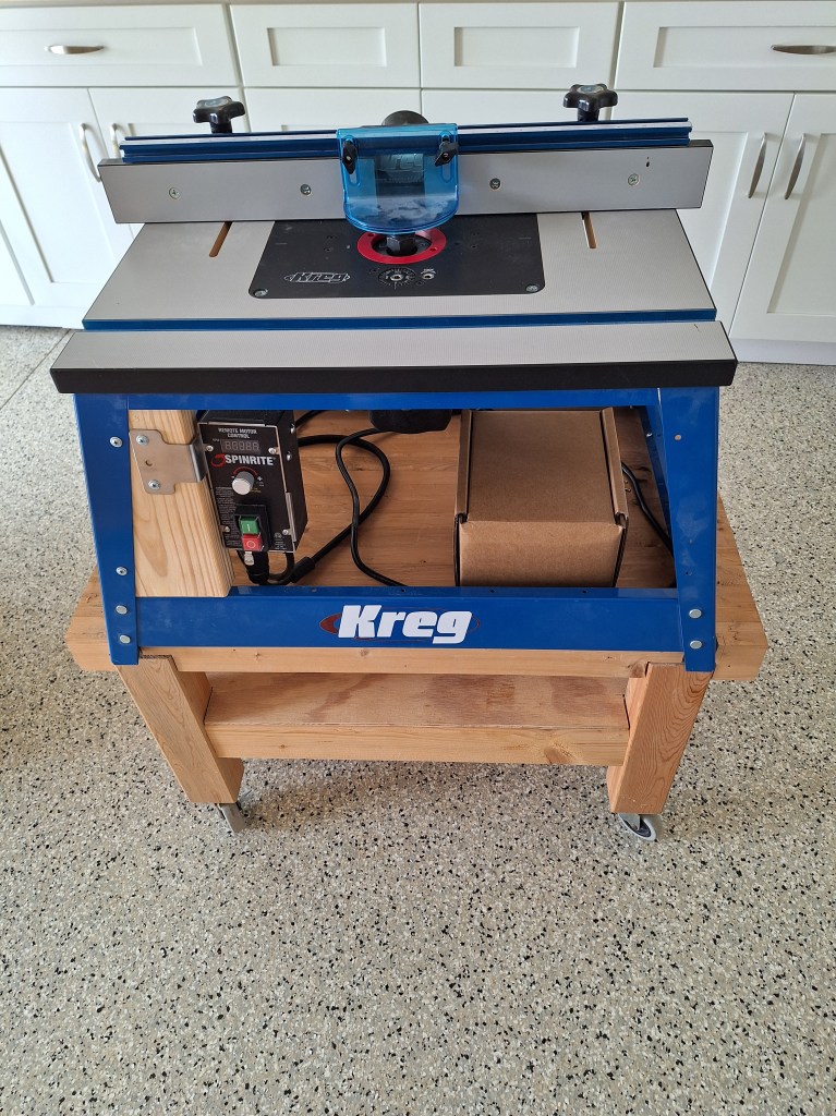
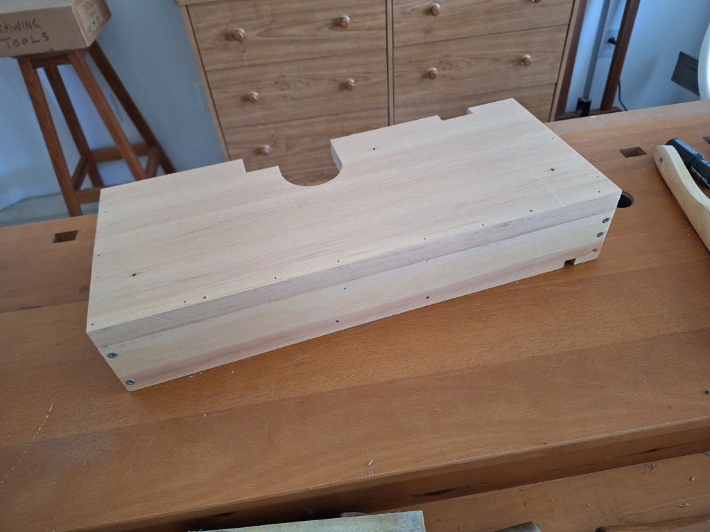
Unfortunately, it became very clear that the router table was not going to be sufficient to do the job. The material, especially the panels, were just too large and beefy for my little router table. Pushing them over the router table would be very precarious, at best. So I started looking at shapers, also known as spindle molders. Shapers are kind of like router tables, but much bigger. Where router tables accept router bits (cutters attached to a shaft), shapers have spindles upon which cutters are installed. Router bits usually come with shaft diameters around 1/4″ to 1/2″. The shaper spindles are commonly 1-1/4″ diameter. I had explored the idea of getting a shaper before ordering my router motor, but thought I would first try using the router table before investing in such a large piece of equipment. After it became obvious that it would not work, I returned to the idea of getting a shaper. So I had already done quite a bit of research on shapers. Now that I was almost certainly going to buy one, I only had a bit more work to do to decide which one. I ultimately decided to buy a Powermatic 2700, as shown below.

PM 2700 Shaper
PM 2700 Shaper

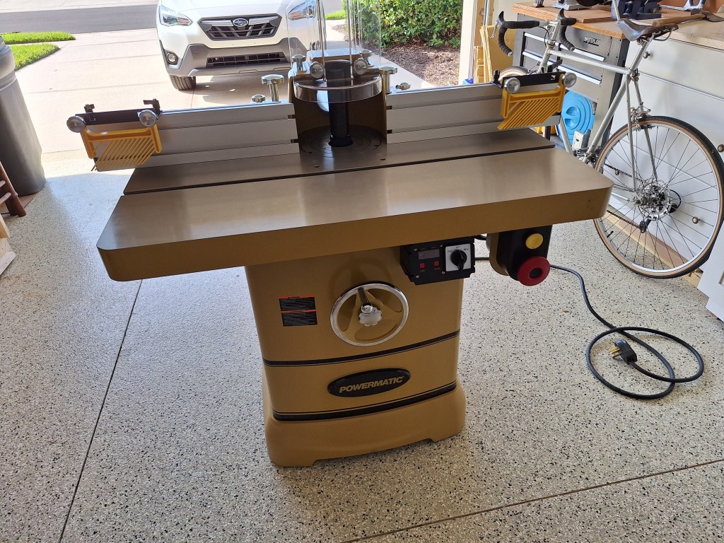
This machine is very heavy, around 600 pounds, but under the cabinet are a set of retractable casters that are raised using a handle on the left side (same kind of handle as you see on the front of the machine). So I am able to move it into a location I made for it, allowing me to continue to pull my car into the garage.

Buying this machine required that I add yet another 240 volt outlet. The 240 volt outlet added for the jointer was wired for 20 amps. This machine required 30 amps, so another outlet was needed. This time I decided to install the outlet myself. The price tag for the first one was pretty hefty and I did not want to incur that cost again. Fortunately it was a pretty simple job and I had it done is a couple of hours.

240 Volt, 30 Amp Outlet

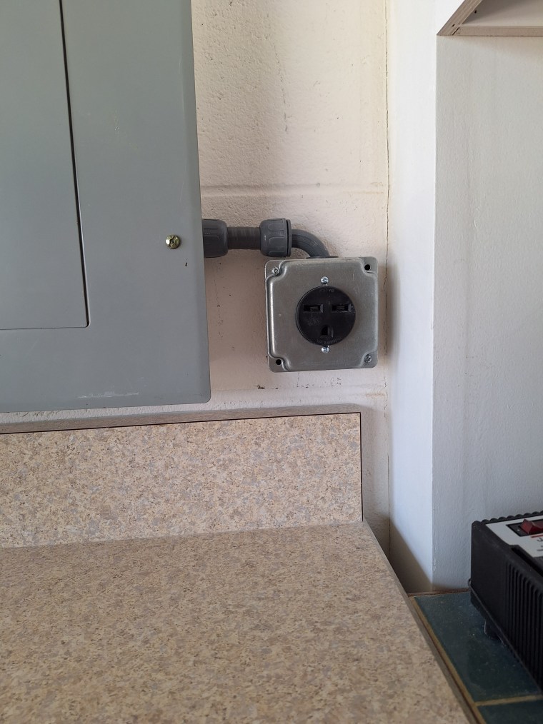
So now I have two 240 volt outlets sitting next to my breaker box.

The two 240 Volt Outlets

Because a machine like the PM 2700 is commonly purchased by a business, the electrical setup cannot be anticipated. That is, the business may have anything from a 30 amp outlet to a 50 amp outlet, or may even wish to hard wire the machine to a power source. As a result, the machine is not shipped with a power cord. So I had to make up my own power cord and wire it to the shaper.

Electrical Connection for the PM 2700

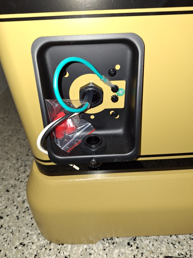
In the first image of the shaper shown above, you can see the power cord I made up sitting on the floor to the right side of it.

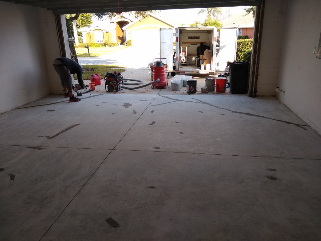
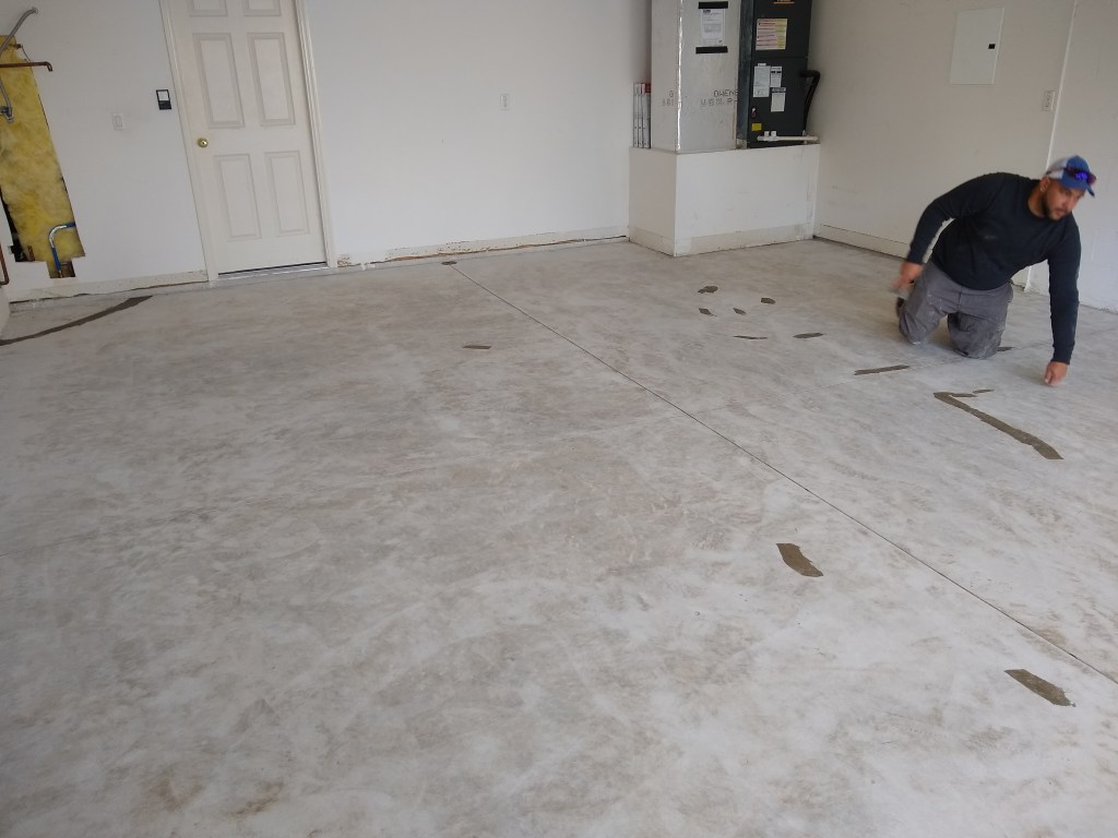
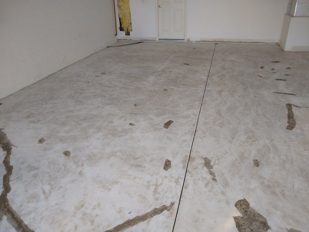
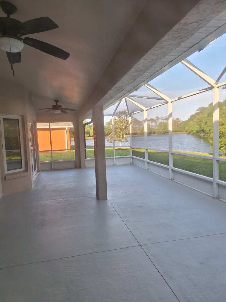
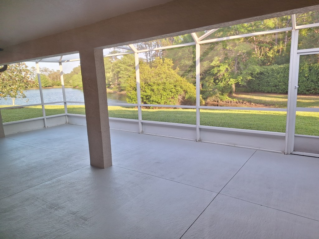
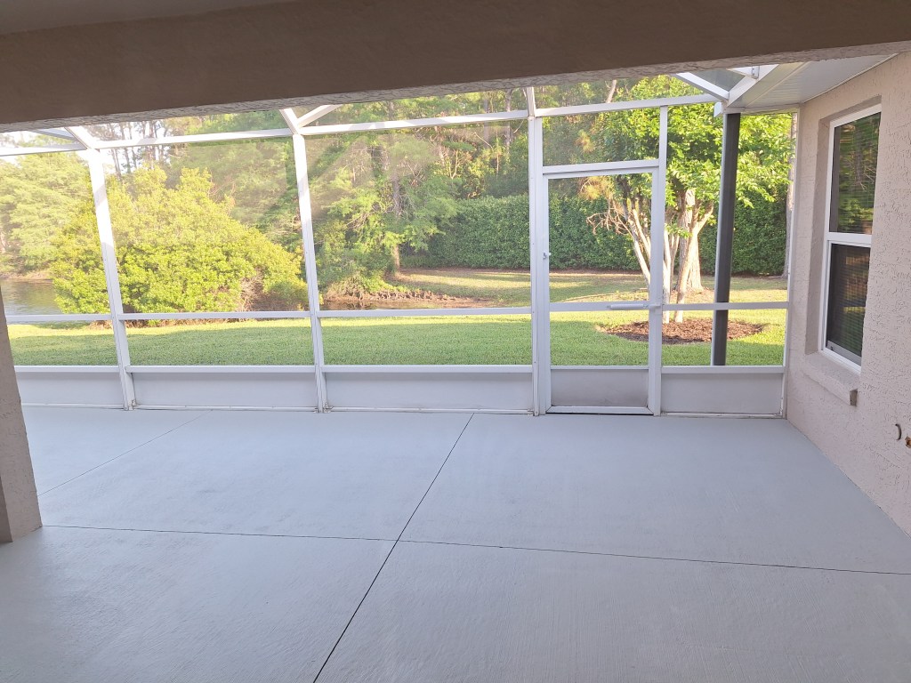
After ordering this machine, I had to wait about a week before it was delivered, so I used that time to clean up the floor of the lanai. I had it pressure washed, then added a couple of coats of paint to freshen it up. I’ve had several ideas of what I’d like to do with the lanai floor, but for now, I just wanted something more inviting since I will not attend to that project for a very long time.

Lanai – Looking East
Lanai – Looking South East
Lanai – Looking South

Once the PM 2700 had arrived, I had to decide on the cutters I would need. Like everything, this required some research. To raise the panels, I settled on a cove cutter that would provide a nice long but simple cove that would reflect what I modeled in FreeCAD. To cut the groove in the stiles and rails, into which the panels would slide, I ordered a 1/2 inch “groover”.

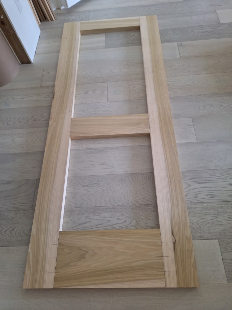
Once the cutters arrived, I got to work preparing the stiles and rails for cutting the grooves that will accept the panels. To start, I laid them out on the floor to establish where exactly I would position the rails.

Layout before cutting Stiles/Rails to Final Length

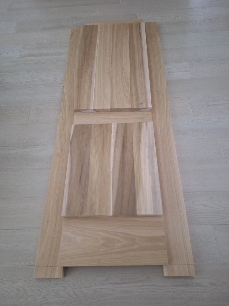
I set the panels on top of the stiles and rails to make sure they overlapped by about 3/8″ all the way around. The grooves I would cut into the stiles and rails would be 1/2″ deep, leaving 1/8″ for expansion. With the distances marked, I was able to cut the stiles and rails to final length then cut the mortises for the Domino joinery.

Mortises Cut using Festool Domino, ready for Dry Fit
Dry Fitting using Dominos
Dry Fit Complete

I was happy with the dry fit, so it was time for me to pull it apart and cut the grooves that would receive the raised panels. Having never used the shaper before, I would practice cutting the 1/2″ grooves on scrap pieces to get a feel for it. After experimenting with the shaper, I was really surprised at how well it worked. It produced the 1/2″ groove at 1/2″ depth easily and cleanly in one pass. I had intended to use my prototype door pieces at this stage, but after this I felt I was ready to go on the real thing. So, after all was said and done, I did end up abandoning the prototype door.

Cutting Groove in one of the Stiles
Shaper Output as I ran the Stile past the Groove Cutter.

I did the same with the rails, which were much easier given the shorter length. The key to getting the grooves to line up properly was to make sure the “reference” side of each board was face down as it ran through the shaper.

Showing how the Grooves Line Up
Dry Fit after Grooves cut

For reference, the door is 81″ tall, 32-5/8″ wide. The bottom rail is 10″ wide, the middle (lock) rail is 6″, and the top rail is 5″. The stiles are 6″ wide.

With the grooves cut and the door dry fit, the panel openings could be measured to provide the final dimensions for the panels before running them through the shaper to create the raised panel effect. To cut the panels to final dimensions and square them, I purchased another new tool, the Festool TS 60 track saw with guide rail. I knew this tool would be needed eventually. This was one of the jobs it would be needed for, so I got it.

Cutting Bottom Panel to Final Dimensions

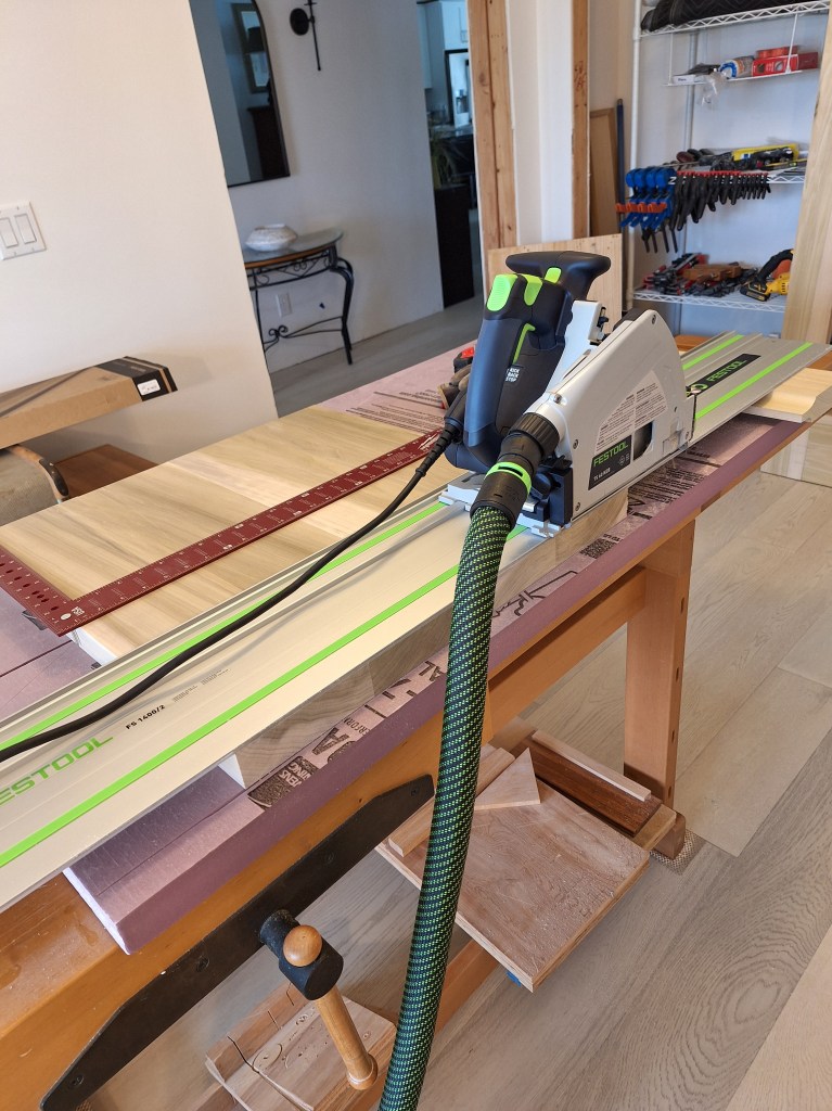
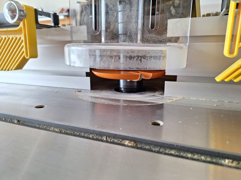
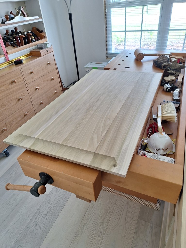
With both panels square and at final dimensions, it was time to run them through the shaper. I installed the panel raising cutter in the shaper then ran some test pieces through to establish the height of the cutter. I would be raising the panel on both sides, so the remaining tongue needed to be able to fit into the grooves in the stiles and rails well, but not too tightly. If you look at the image above, you can see that I used the test piece I ran through the shaper to support the far end of the track saw rail. Below I show the cutter installed in the shaper.

Panel Raising Cutter

This was a critical operation because if I made a mistake, I’d have to remake the panels. That would be a big job and expensive because of the cost of the wood, so I was at full attention when doing this. My experience with the test piece gave me a sense that it would be fine, but I was still a bit nervous about this operation. Although I didn’t have to, I decided to run the panels through the shaper using two passes. For the first pass, I moved the fence forward so that I would take about 75% of the material off. After that I pushed the fence back to expose the full extent of the cutter and ran the panels through again for the final pass. This worked flawlessly and I was delighted with the results. This was definitely the tool for the job.

Bottom Panel Raised on Both Sides

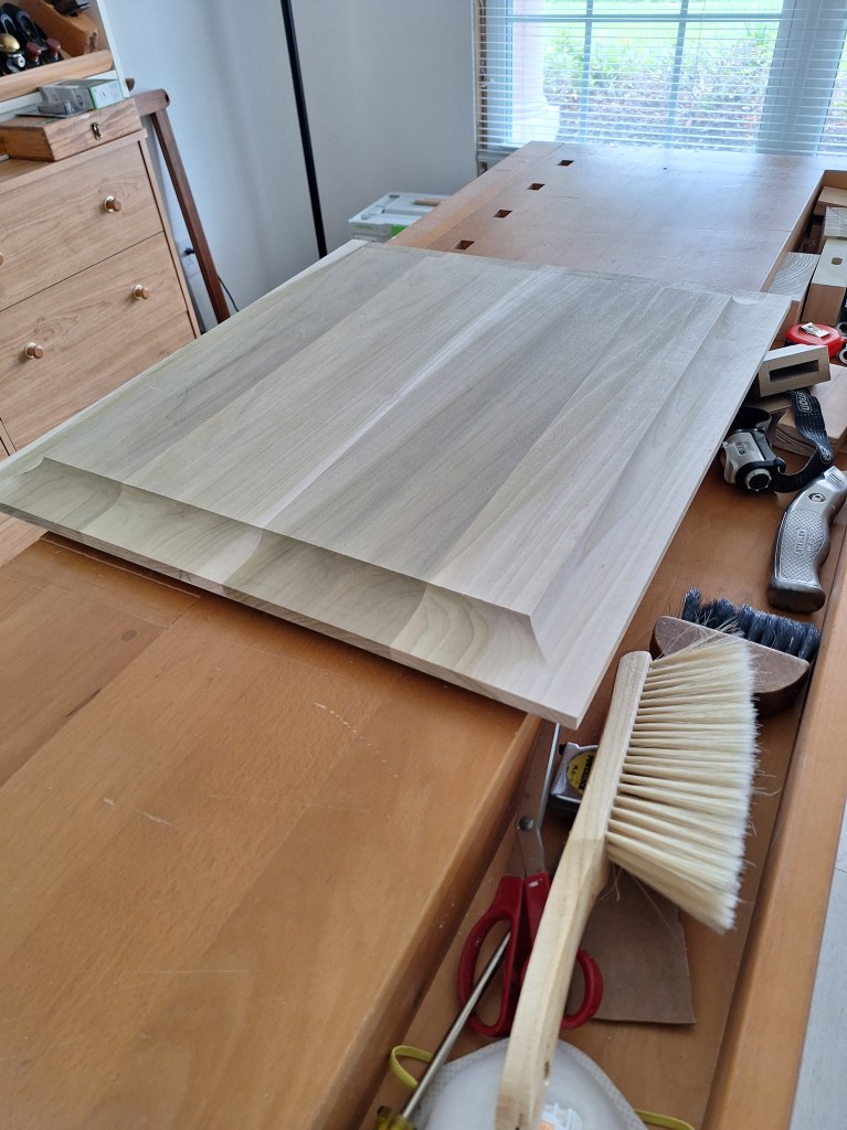
Before raising the upper panel, I did a quick dry fit of the bottom panel in the frame to make sure there were no surprises. It fit well.

Dry Fitting Bottom Panel

I ran the top panel through next.

Top Panel Raised on Both Sides

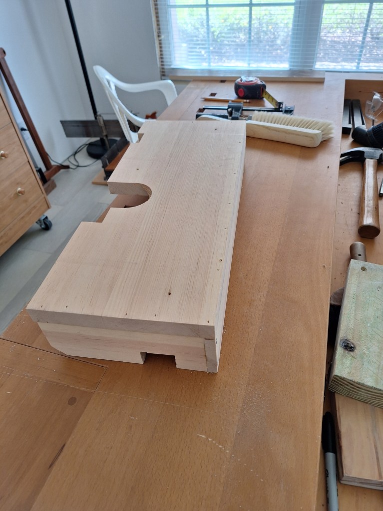
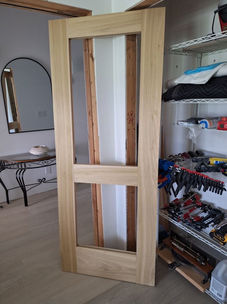
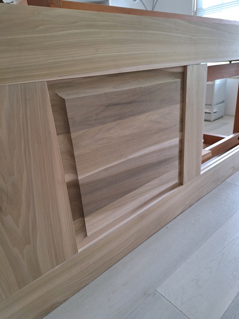
Again, I was pleased that the operation went smoothly. With both panels raised, I dry fitted them into the frame to reveal something that looks like a door.

Dry Fit of Both Panels

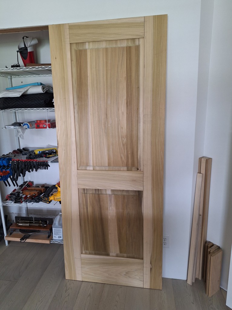
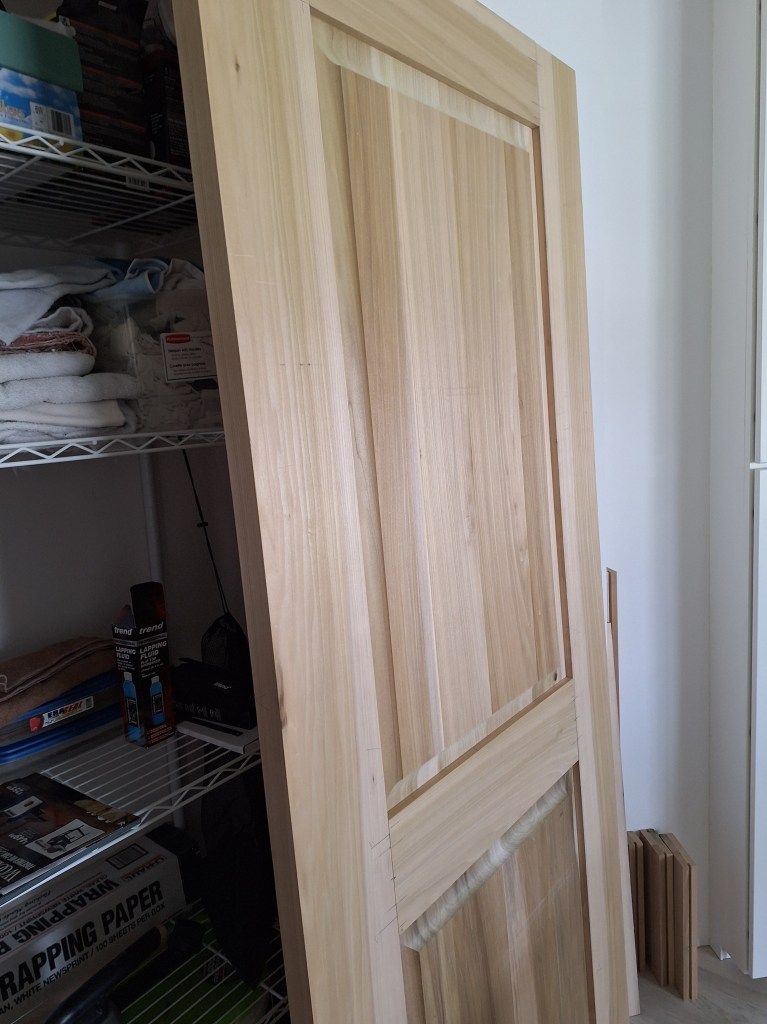
I was very pleased with that. Although there were still many stages to go (sanding, glue-up, painting, pre-hanging into the door jamb, hardware, etc.), I finally had something that I could visualize.

I intended to end this post with a finished and installed door, but before I can move on with this door I have other equipment I want to obtain to make the process easier. I have many doors to make, so I want to get a system in place to make them as well as I can. Besides, this post is already long enough, so I’ll end the it here and discuss the next steps in the following post.

Kitchen, Garage, and other bits and pieces – May and June 2025

After a really nice week away, my first task upon returning to the house was to figure out how to hook up the vent hood. Just prior to leaving on vacation, I was speaking with a metal fabricator about creating custom piping to route the vent exhaust through the limited space in the cabinet above the cooktop. The situation is like this:

Cooktop Cabinet Venting
Cooktop Venting Dimensions

The hole in the bottom of the cabinet is 7″, and the one at the top is 6″. There is little space within the cabinet, so off-the-shelf parts would not fit. Hence, the need to speak to a fabricator. After that discussion I learned that it was going to be very expensive, so I started looking for alternatives. I found a short reducer online that would reduce the 7″ exhaust port of the vent hood to 6″ and take up minimal vertical space. A 90 degree elbow would then be needed to turn in the direction of the flex pipe. I ordered both, hoping they would work. They did not. So I found another metal fabricator that claimed they could do it for far less than the first one I contacted. So I handed the job off to them. The results of that will be presented in a subsequent post.

While attending to the exhaust venting, I used some of the wait time to add a switch and 4″ recessed light in the hallway between the master bedroom and bathroom.

Overhead Light in Hallway
Switch and Overhead Light

Above the door to the bathroom will be glass, allowing the natural light from the sun tunnel in the bathroom to extend into the hallway. By adding a recessed light, there will be no fixture to obscure it.

My piano would be arriving soon, and it would be going in the dining room. Therefore, I needed to install a light fixture there before the presence of the piano got in the way.

Light Fixture in Dining room
Light Fixture in Dining – On.

I really like this fixture. I stayed with the matte black with white shade theme. Like the other fixtures, I will be keeping the cellophane on to protect the shade until I move in. Once installed, I cleared the area to make room for the piano, which arrived a few days later.

Piano Delivered

I subsequently purchase a new piano bench.

Piano Bench

When ordering the light for the dining room, I also ordered a similar but smaller one for the laundry room.

Light Fixture in Laundry Room

A lot of other work took place during this time. I ordered the items I’ll need for the kitchen island This included: the sink, faucet, popup outlets, and pressure switch for the garbage disposal. Those would be needed in order to know the cutouts required for the counter top. Once they arrived, I created the required sketches in SketchUp, which I’ll take to the company that will be doing the work. Here’s the one for the island.

Sketch of Island Countertop with Cutouts

I also ordered the remaining equipment for the network rack, which included a UPS (uninterruptible power supply), a 24 port switch, and some other bits and pieces. The modem and router were supplied by my internet provider. Once they arrived and the cable guy activated the connection, here’s what I ended up with.

Network Rack

The top two slots contain patch panels. They are used to organize the 30 different cables I have running throughout the house, each terminating at a wall jack. In some places I have two jacks at one location. Here are a couple of examples.

Below the patch panel in the rack is a switch with 24 ports. Although I have more cables run than switch ports, in practice I will not use all available lines, so a 24 port switch is sufficient. If I need to use one that is not hooked up to the switch, it is easy to swap them around.

The router connects to the switch (the yellow cable), which will distribute the connection to the other ports and, ultimately, to the jacks through the patch panel. Below that I have a gap (unused slot) followed by a power strip. Below that is my uninterruptible power supply that plugs into the wall. All power goes through it, meaning all power in the rack is backed up by a battery and surge protected. The yellow cable connects the router to the switch, and the router is connected to the modem. As previously mentioned, the router and the modem were supplied by the service provider. It is nice to have internet access in the house again.

I purchased a nice little labeling machine. It will be used to identify the jacks. I also used it to label the water lines coming out of the Manabloc.

Manabloc Labeled
Manabloc Labeled – closeup

I will have lots of opportunity to use my nice little label maker elsewhere throughout the house.

Next, I went out to select slabs for the countertops. The process involves selecting the slabs, then arranging to have the fabricator receive them and take the measurements required to do the cutting and fitting. I identified a pair of book matched slabs for the island because one slab was not long enough to cover it. The cooktop area was much smaller, so one slab would provide far more material than I needed. The slab I am showing below is for the island. It is quartzite with only faint veining.

Slab for Kitchen Island

Unlike the island, the slab I selected for the cooktop area is granite, due to its ability to withstand heat better than quartzite. It is called Black Absolute and is shown below. The image below was taken at the fabricator because they just happened to have an off-cut of Black Absolute from another job that was the right size, so I didn’t have to buy a full slab for the relatively small area that needed it. Although it looks like there are some lines in it, there are not. Those are just streaks from the cutting process that dried.

Black Absolute Granite Slab

After selecting the slabs, they would have to be delivered to the fabricator and then I would have to wait until they had time in their schedule to start cutting them. In the meantime, I attended to some other things I wanted to get done before the countertops were ready for installation.

To cover and protect the some of the things at the bottom of the sink cabinet in the island, I built a box to enclose them. Here is what I was dealing with.

Components in Sink Cabinet

I wanted to create something that I could slide into place and cover the junction box, power adapter, and controller for the kick lighting, and surround the water supply lines and drain. Here is what I built.

There are various openings cut into the sides to make room for the wires and cables that enter/exit. The cutouts in the top are for the water supply lines and drain, and one for the wire to the junction box above it. Here it is installed within the sink cabinet.

Installed

This was made from some scrap pine I had, so it’s not too heavy, yet provides a solid enclosure. You just set it in place and slide it against the back of the cabinet to enclose the drain and water supply lines. It fits nicely in the space, covering exactly what I wanted. I will probably some Velcro to secure it to the back wall so I can easily remove it to gain access to the components within. I ended up increasing the width of the opening I made for the water supply lines because I needed to space them out more in order to secure them and make room for the straight stops I installed.

Water Lines Secured

In the image above, I did not install the straight stop for the supply line to the dishwasher because I had yet to explore how to install the dishwasher, so I left it plugged and long.

The countertop process took longer than expected. This added a lot of down time to the renovation, and was the reason I did not finish this post in time to publish it at the end of May. I did not want to start a new project until after the kitchen was done, because none of the other projects would prevent me from moving into the house. Plus, I didn’t want to start something I might have to stop once I could move forward with the kitchen after the countertops were installed. Although not a prerequisite for moving into the house, while waiting I decided to start the process of getting the vanity mirror for the master bathroom. It will be one large mirror spanning the width of the vanity, so not something I could do myself. I had someone come out and measure and I subsequently ordered it. That too, would take some time, but another job initiated.

Eventually, I got fed up doing nothing and decided I had to start the next project. After the kitchen was done, I intended to turn my attention to the garage and setup a proper workshop, where I would be able to do the work needed to trim out the interior and, if adventurous enough, make the interior doors. This would be a big job, but one I could do in stages, so I decided to start by framing the west wall of the garage so I had a place to hang things and store long items. Here is what it looked like after I moved things out of the way.

West Wall Before Framing

And here it is after I framed it.

West Wall Framed

This is a twelve foot span. I did not take it all the way to the front wall of the garage because I thought I should leave some space because it can get a bit wet there if it rains. With this in place I added a high shelf from left over shelving from the closets inside the house, and several 1×6 horizontal boards to provide a place to attach various fixtures for hanging things.

Horizontal Members Added

I had a similar setup in my other house, and it worked well, so I decided to duplicate it here. The high shelf allows me to store very long things up out of the way. With the horizontal boards, I have the freedom to add or move fixtures as needed. Here’s what I’ve added so far.

First Items Hung
First Items Hung

It’s nice to have the yard care items off the floor. I’ve positioned them near the front of the garage. Near the back I have my desktop router table hung on the wall along with several extension cords. I will leave the space under them clear so that I can move equipment there, as you can see below.

Equipment Put in Place

This will remain a work in progress. I intend to acquire some new equipment and replace others to better assist me with my woodworking objectives, which will be captured in future blog posts.

After getting the wall up, I decided it was time to finish the butcher block countertop. So I pulled off the plastic wrap and moved it to an area where I could apply finish to all surfaces. Up until now, that butcher block countertop had be simply sitting, unattached and wrapped in plastic, on the base cabinets for a very long time.

Finishing the Butcher Block Countertops

I also picked up a 4′ piece of Butcher Block countertop and cut it into two pieces. One will sit on the 15″ base cabinet along the back wall of the garage, and the other on the 18″ base cabinet along that same wall.

Finishing the Shorter Countertop Pieces

I will be adding three or four coats of a clear polyurethane; as many as I can get out of the one quart can. Between each coat I lightly sand.

While I was “fabricating” the countertops for my garage cabinets, I paid a visit to the shop where my kitchen countertops would be cut to size. It was very nice of the guys to let me see how it’s done. When I asked if I could watch, I was expecting them to decline, but to my surprise they agreed. So here is what I saw.

The Two Quartz Slabs that will make up the Island Countertop
Moving one of the Island Slabs to the Cutting Table
Rotating the Cutting Table
Cutting the Slab

Returning to my work in the garage, after adding all the finishing coats to the butcher block countertops, I was ready to attach them to the base cabinets.

Countertops Installed

Notice that I also added some open shelving above the 18″ base cabinet on the back wall. That was always my intention, but what was different was that I made use of some of the left over wire shelving I had stored away. It’s always nice to reuse things.

Open Shelving Added

With all the waiting around that was required as I navigated the kitchen countertop journey, it was nice to be able to make progress in the garage, even though it was not required for moving in. Next week is the beginning of July and I am expecting the kitchen countertops to be installed. That will make for an interesting post. Until then…

Ceiling Prep, Garage Cabinets, and More Drywall Hanging – January/February 2023

After returning from the holidays, I knew I would still be waiting for a while before I would have anything from Jennifer, so I decided to continue work in the garage as best I could. I was still missing a 24″ pantry cabinet that would be the center cabinet along the back wall of the garage, so I did as much as I could in the meantime. This meant adding baseboard, painting the walls, and installing two cabinets of the five cabinets that will go along that wall.

This was all I could do along the back wall since the next cabinet to go in was the missing 24″ pantry cabinet. Not wanting to be idle, I shifted my attention to a task I was not looking forward to; preparing the kitchen and great room ceilings for painting.

Prepping the ceilings meant filling all cracks with wood filler, sanding, then caulking. This would be a long, slow, and laborious task, and one that would require standing on a scaffold working above my head. However, it is a very important task, as it would mean the difference between a great looking ceiling and something less than that. So I got to it.

First Coffer Prepped
First Coffer Prepped, alternate angle.

I started with the kitchen ceiling and then moved on to the coffered ceiling. I didn’t take any pics of the kitchen ceiling because there wasn’t much to show other than sanding marks and such. You can kind of see it in the background of the images above. These images are the only ones I took of the coffer prep because once you’ve seen one, you’ll have seen them all. I had 17 coffers to prep and the images above are of the first one. It took about four weeks to complete both the kitchen ceiling and the coffered ceiling. It was hard work, but I am pleased with the results. Once the primer goes on, I’ll know if any further action is needed, but I suspect not (only very little if any). I don’t plan on priming/painting the ceiling until all the walls are ready to prime/paint, and that is a long way off.

I finished the ceiling prep work the day before the missing garage cabinet arrived, so I was able to return to the cabinet installation in the garage right away. I finished installing the cabinets along the back wall in a single day, resulting in this:

Back Wall Cabinets

Note that above the base cabinet on the right, I will add open shelving, but not anytime soon. Here is a shot of all the garage cabinets before adding the hardware.

All Cabinets Installed

The next day I added the handles. Doesn’t that look nice!

Handles Added
Handles and Butcher Block Countertop

You’ll also notice that the butcher block counter top is in place along the east wall, but not attached. It is still wrapped in plastic and I won’t remove the plastic and apply finish to it until I have moved in (or am at a stand still – heaven forbid), as it is of low priority. I’m still waiting on the corresponding countertops for the outside base cabinets on the back wall, but, again, no hurry.

With the work in the garage done for now, I was ready to return to work on the inside of the house, but unfortunately and frustratingly, still no construction drawings from the designer. We had settled on the design changes to the kitchen and master bathroom, so she is supposed to produce construction drawings that I will submit to the permitting office to update my permit. Not wanting to wait, I scheduled an inspection of the master bedroom (framing and electrical) so I could push on. The inspection went without incident, so I resumed work in the master. The first job was to add insulation.

Once that was done I started hanging drywall. I started on the south wall.

South Wall

The next day I worked on the west wall, which required I first add a patch to the ceiling where I previously opened it up to feed the Ethernet cable.

West Wall

I used the two remaining 12 foot long sheets along the west wall so that I could limit the butt joints to above and below the window, so less work required when taping.

I continued in a clockwise manner to complete the room.

North Wall
Northeast Corner
East Wall

On the ceiling along the east wall I had to do another patch, again due to adding an Ethernet line.

When the inspectors came to look at the master bedroom, I also had them look at the wall in the workshop that I framed. Recall that I originally hung drywall along the west wall of the workshop only to pull it down when I discovered that the entrance to that room was messed up. So I framed that wall as I did in the master and had the inspectors give me the okay on it too.

West Wall of Workshop Framed

So I insulated and hung drywall along that wall next.

My next step will be to bring the inspectors in again to okay the drywall I just put up so I can begin taping and mudding. My preference was to call them in only after all the drywall was up, but with the poor response time from the designer, I am requesting inspections piecemeal so I can push on with the things I can control.

I will be off to Cancun for a few days to meet up with family and friends to celebrate a significant birthday of a family member, so I will resume work at the beginning of March.

Potential Design Changes and Garage Work – November/December 2022

As mentioned at the end of the last post, I met with Jennifer, my designer. Among the usual business of selecting materials and such, a new idea for the kitchen came up. She was struggling a bit with how I wanted to have the island centered and facing the french doors. She was concerned about the limited work space and ergonomics. While meeting with her at ProSource, we were in a display area with a really nice island setup. I mentioned it and she said we could do that if we removed the wall separating the kitchen and great room. This was not something I had considered. I had always had my heart set on standing at the sink and facing the french doors and the view that presented. I also liked the idea of having a bit of separation between the two rooms. But I did understand her concerns. So when she presented this idea, coupled with the showroom kitchen we were standing in, I was intrigued. So she will be providing me with two designs: one with the original plan, and another with the new idea she is proposing. More on that when it materializes.

In the meantime, I shifted my attention to the garage, because it is not dependent on Jennifer’s work. Here is how the garage is to look (I’m using the free version of SketchUp, so I’m stuck with the SketchUp label you see in the upper right corner).

East Wall on left, adjacent to Back Wall

I had already framed the east wall of the garage and run wires for the electrical. But the back wall required some work to add two new outlets on either side of the tall cabinets that will be installed there. There was a single outlet on that wall, which would be blocked by the tall cabinets. So I wanted to replace it with an outlet above each of the base cabinets that flank them. To do this I had to remove the drywall so I could run the wire. Here’s what I came up with.

Back Wall of Garage after new Outlets added.

The source power comes down from above. It feeds the outlet on the left, then connects to the outlet on the right, then back up to the outlet up top where it continues to provide power to outlets on the adjacent wall on the right. The outlet up high was originally at the same level as the others but in the middle of the wall, therefore it would be blocked by the tall cabinets that will be placed there. So I decided to move it up above the tall cabinets and run the wires from there. Originally I figured I would just make it a junction box, but decided it might be handy to have an outlet above the tall cabinets at some point. Either way, a junction was needed and junctions cannot be inaccessible (by code), so even though it is up high, it is accessible.

After sorting that out, I proceeded to add blocking, which is what the cabinets will be secured to. Strictly speaking, you don’t have to add blocking. You can just use the existing framing members, but that provides a much smaller target, so I opted for the blocking.

Another thing I did was replace the rightmost 1-gang outlet box on the east wall with a 2-gang box that would provide an outlet and a switch for under counter lighting. I thought that would come in handy and would be good practice for when I do it in the kitchen.

2-gang Box added to support Under Counter Lighting

Before putting up drywall, I needed to get an electrical and framing inspection. This was scheduled and successful. My first time! I’m now a man of the world. One of the benefits of having passed an inspection is that each successful inspection extends the expiration date of the permit by 6 months. My permit was due to expire in February, so I’m good for a while now.

With the inspection done, I proceeded to add insulation and start hanging drywall.

Insulation and first board added to East Wall

If you look closely at the upper right corner, you’ll notice a wire extending from a junction box. This is 240 volt line that feeds the hot water heater. It originally entered the garage from the adjacent wall. Now that I have framed the east wall of the garage, it is a more direct route to have it enter from there. So I moved it and now it is no longer within the plumbing closet in the laundry room.

I should say something about the insulation. It may seem a bit silly to insulate part of a wall given that the rest of the wall (and the opposing wall, not to mention the garage door) is not insulated. I decided to add it because I may want to insulate the entire garage in the future. Of course, the back wall must be insulated because it separates the garage from the inside of the house.

Insulation added to Back Wall

And here are some images of the walls with the drywall hung.

Before I can begin taping and mudding, another inspection for the drywall was needed. I scheduled it and there were no issues. With that inspection complete, I can now proceed without the need for any further inspections for the garage work. So I got busy taping.

It is questionable whether I needed to do any more mudding at this point because most of this wall space will be covered with cabinets, but I decided to continue, mostly to experiment. In my first experience doing drywall (guest bedroom), I used a different kind of mud for my final (skim) coat. It was a lighter mud called Plus 3, and I liked it. It spread well and sanded well. So this time I wanted to try using an all-purpose mud to see how it worked for skimming. I watered it down to make it easier to use, but in the end, I think I preferred the Plus 3 for a final coat. I only did a skim coat on the back wall. I didn’t have enough mud to skim the east wall, and since it was not needed I wasn’t going to buy more. Unfortunately, I forgot to take any pics of the process and only thought about it as I was priming the east wall, so I don’t have an image of the skim coated back wall. Here is a pic of the east wall in the process of being primed.

East wall in the process of being Primed

Here are images of the walls after the primer (Kilz 2) was applied.

One could install the cabinets at this point, but I decided to add a top coat of paint before doing that since it will be much easier with the walls bare (i.e., no cabinets in the way). I also wanted to put up a trim piece between the east wall and ceiling. Here is the result.

Top Coat and Trim Added

Cabinet installation along the east wall was next. It’s common to start by installing the upper cabinets first so that the base cabinets are not in the way. Often one will put up a ledger board to support the wall cabinets as they are positioned, especially if working on your own, as I do. But I saw a video on YouTube where the guy installed the base cabinets first and used a makeshift bench to support the wall cabinets. I will elaborate on this in a moment.

Base Cabinets Installed – looking toward back of garage.

Installing the base cabinets required quite a bit of shimming, since garage floors are sloped for drainage from the back of the garage to the front. I started by using my laser level to establish where the top of the base cabinets needed to be. Using a laser level is a luxury, and I was happy to benefit from it. The first cabinet to be installed was the one closest to the front of the garage (nearest cabinet in the image above), since I wanted it to line up with the edge of the newly framed wall. It required a pretty big shim to elevate it to level, so I cut my own and used my thickness planer to get it just right. You can see how the gap below the cabinets decreases as you move toward the back of the garage. This will eventually be covered with a continuous strip along the kick plate.

Base Cabinets Installed – looking toward front of garage.

I managed to install all the base cabinets in one afternoon, albeit a long afternoon. Having never done this before, I was pretty happy with that. The next day, I started on the wall cabinets.

Installing Wall Cabinets

As mentioned above, I adopted an approach to installing the wall cabinets from a video I saw on YouTube. What appealed to me about the approach was that it was well suited for a single person installation. With the base cabinets installed, all the leveling work is done and you can benefit from that by simply referencing off it. The idea is to construct a simple bench (shown above) out of whatever pieces you have lying around and make it tall enough to reach the bottom of the wall cabinet with about an eighth of an inch to spare. You then place the wall cabinet on top of the bench and use shims to make up the difference to get the cabinet exactly where you want it. Once the cabinet is secured, you remove the shims, allowing the bench to be easily extracted. This worked like a charm and I was so pleased I came upon it. Putting up the wall cabinets was a breeze using this approach.

Wall Cabinets Installed on East Wall

The wire hanging down beneath the upper cabinet will be used for under counter lighting. The gap between the wall cabinets is a consequence of these cabinets being originally intended for my other house before I sold it (without actually replacing the kitchen). In that house, the base cabinet for the sink did not have a cabinet above it. So I decided to use that space for open shelving.

Open Shelves Installed

To create the open shelving, I had to improvise a bit. I had some cabinet pieces I wasn’t sure what to do with. One piece was a side panel with a return (the thick bit below the bottom shelf) that was intended for the dishwasher at the other house. I cut the panel in half and used the return as a facing to match the lower rail of the adjacent cabinets, forming the lower shelf. I think it looks great and has the added benefit of concealing the under counter lighting in the same way the cabinets do. Nice!

The two upper shelves were constructed from a refrigerator panel I decided not to use. I originally intended to use the two refrigerator panels to flank either side of this bank of cabinets (see image at the beginning of this post), but decided it looked better and would function better without them. So I cut what I needed from one of them. I also decided not to add a piece at the top to join the cabinets, as is shown in the SketchUp drawing above. That would limit what I could put on the top shelf. So far, I’m very happy with the way this looks.

I will add a butcher block countertop to give it a workbench look. I will attend to this in early January, as I will be away over the holidays. I also intend to add some sort of slat wall system as a backsplash so that I can hang things on it and move them around as I see fit. But I won’t get to that until it makes sense. I would normally move directly to installing the cabinets on the back wall of the garage, but I am still missing a cabinet. Hopefully that will arrive some time in January and I can continue.

As for the design updates from Jennifer, she just sent me two options for the kitchen. I really like one of them and will be meeting her in a couple of days to go over it. It will probably still be a while before I am able to move forward on the interior of the house, even after we are settled on the design. If the kitchen layout changes, as I expect it will, I will probably have to update the permits. But I still have plenty to do in the garage, so I will continue with that in the meantime.

That’s all for this post as I will be leaving shortly for Christmas vacation. Happy holidays!

Delays and Garage – January/February 2022

At the end of the last post I mentioned that I would be meeting with an electrician to discuss adding a 240 volt line for the cook-top. That meeting changed a lot. We had a really good chat and he was kind enough to educate me about permitting. He walked through the house and pointed out a number of things that I should be aware of, but most importantly made me realize that I really needed to get permits for the work I have been doing. Many people proceed with interior remodels without permits, but they really shouldn’t. In my case, the changes were so significant that I really needed to follow the process and have proper inspections done. Even though I have no plans to sell the house, one never knows if that will change. If I do decide to sell, the massive renovations that were performed without permits/inspections could cause problems.

This may seem rather obvious, but I was following Chris’ lead on this and he did not want to go down that road. After my discussion with the electrician, I understood that I was skirting the system, and I was not comfortable with that. I decided it was time to set it straight. So I started looking into what was required to get permits. I called the permitting office and they filled me in. I could sign an owner/builder affidavit that allowed me to be my own general contractor (GC), with the understanding that I was responsible for hiring fully licensed and insured contractors. For work I would do, I had to apply for permits myself. The idea of having to wade through the bureaucracy was not appealing, so I started to entertain bringing in a general contractor to manage it and even hand off some of the work. Although this would cost considerably more, the benefit would be that the work would get done sooner and I should be able to move in before the end of the year, thus avoiding the need to renew my apartment lease.

I contacted three different GCs. One fellow, we’ll call him GC1, was busy but would call me the following week to discuss further. I made appointments to meet the other two. The first fellow I was to meet, GC2, was late. I eventually texted him and he somehow lost my information. My text was what allowed him to find it (?). So he eventually showed up and we did a walk through. As we spoke, I got the impression I only had half his attention as he seemed more interested in his phone. Although he claimed his firm could do everything I wanted, I told him I had other GCs to speak with before I made a decision. As you might guessed, I did not choose him. He did not make a good first impression. The next fellow, GC3, did make a good impression. I liked him and was happy with everything he said. The next step was to bring his engineer in to get drawings together and discuss the plan. I still intended to do as much of the work as possible, but we would figure out who would do what. I told him I would get back to him, as I still had one fellow (GC1) to hear from. GC1 never got back to me, so I let GC3 know that I wanted to work with him. We made an appointment to meet again, and he would bring the engineer with him. To make a long story short, the engineer canceled three separate times. GC3 was embarrassed and was genuinely apologetic. He was going to find another engineer and get back to me. More than a month later, I have still not heard from him. I’ve been abandoned.

Around here, this industry has a reputation for not being reliable. It’s sad, but I’ve heard so many stories about this. So I decided to look further into what it would take to apply for the permits myself. This would require creating construction documents or something deemed acceptable. So I would have to learn a software drawing tool that would allow me to produce such documents. I started learning SketchUp. I’ll get back to that later.

In the meantime, I wanted to do something in the house, so I turned my attention to the garage floor. I expected to do that near the end of the renovation, but since it did not require permitting, I decided to move forward with it. I decided to hire someone to do the work so that I could continue learning SketchUp. I was really happy about that decision because I was delighted with the result.

I moved all the stuff from the garage into the house in preparation for the guys who would be doing the job. I chose an epoxy covering with “full flake”. This would seal, protect, and provide a non-slip surface.

The process began by grinding down the concrete surface and filling any cracks.

Next they applied the base coat, starting with the perimeter then filling in the middle.

Once the base coat was down, it was time to apply the flakes.

Lots of Flakes

They started by distributing the flakes around the perimeter then worked on the middle, from the back to the front of the garage.

After fully distributing the flakes, this is what it looked like.

Flakes Applied

That was left for about an hour before they started on the clear coat.

Here it is after the clear coat was finished. I love it!

Clear Coat Applied

And here is another from inside the house. You can get a better sense of the gloss from the clear coat as it dries.

Clear Coat Still Wet

I left the garage door open a bit until the next morning. I could walk on it later that night, but did not. I decided not to walk on it until it was safe to drive on it, which would be three days. I’m happy to report that this job exceeded my expectations. I’m so glad I hired someone to do this.

This job only took about three hours to complete. I was amazed. My neighbor came by and ended up having them do the exact same thing (color and all) to his garage floor. It did take a couple of weeks before they were able to do the job, one of those weeks due to bad weather. During that time I was busy learning Sketchup, starting by modelling the way I wanted the garage to look. Here is what I came up with.

Front Facing
Looking to the Right

In the image above there are a couple of wall cabinets sitting where the A/C air handler sits (not modeled). I don’t have a spot for them, so I just put them there for now.

Looking to the Left

Before putting the other house on the market, I was going to replace the kitchen cabinets to entice buyers. So I purchase the cabinets at the end of 2019. Almost two years later when I finally put the house on the marked, housing prices took off, so my agent felt there was no need to replace the cabinets. As a result I decided I would use them in the garage of this house, which is what you see above.

These cabinets required assembly, so after the floor was done and drying, I used the time to assemble the cabinets and move them into the garage for the time being. The first one always takes the most time because I’m figuring it out. I started with the 24″ base cabinet (B24), shown below. Notice all the other cabinets in boxes in the background.

My First One. B24.

The next day I assembled the 15″ and 18″ base cabinets (B15 and B18). So getting faster.

Once B15 and B18 were done, I moved them into the garage into the position I will eventually attach them.

The next day I assembled four cabinets: two 30″ base cabinets (B30), the sink base cabinet (SB33), and my first wall cabinet (W30). I moved these into the garage and placed them along the wall opposite to where they will go because I will need them out of the way so I can frame the wall upon which they will be attached.

The following day I assembled W15, W24, W30, and the first 18″ pantry cabinet (P18).

I was missing the 24″ pantry cabinet, which is supposedly on its way, so I only had the second P18 left to assemble. I did that the next day. The missing 24″ cabinet (P24) will fill the opening between the two P18s.

There was a lot of cleanup to do after that, which I got to promptly. Now I am in a holding pattern, with respect to work inside the house, until I get permits. I’m busy modeling the house with SketchUp, which will require a lot more work as I add detail. In the meantime, here is a sneak preview.

Floor Plan

The above image is of the overall floor plan. The garage details shown earlier are not part of this model. I will keep that separate. Below is detail of the plumbing (see past post for the actual work). I intend to capture this sort of detail for all the changes I have made and will make. This will take some time, so I will pick away at it until I have modeled everything I feel is needed by the permit office. Even then, I’m sure they will ask for more. It will be a learning process.

Plumbing in Laundry Room

I’m not sure when I’ll be able to resume work on the house. My priority now is to continue modeling and get my permit applications in. How long it takes to get approval is a big question. It will probably involve some back and forth. Hopefully the next post will shed more light on this process.