Flooring Continued, Kitchen Electrical Work, and Painting the Master Bedroom – March 2025

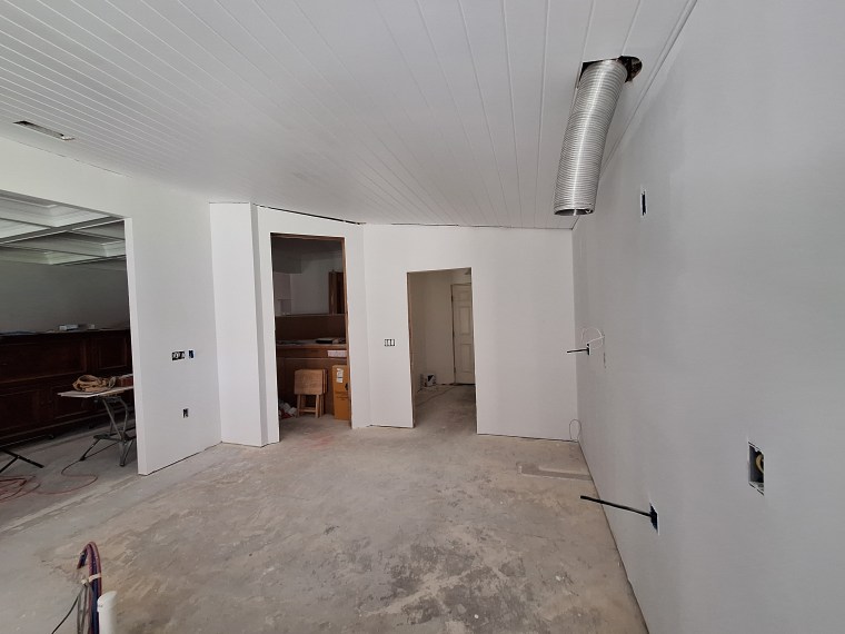
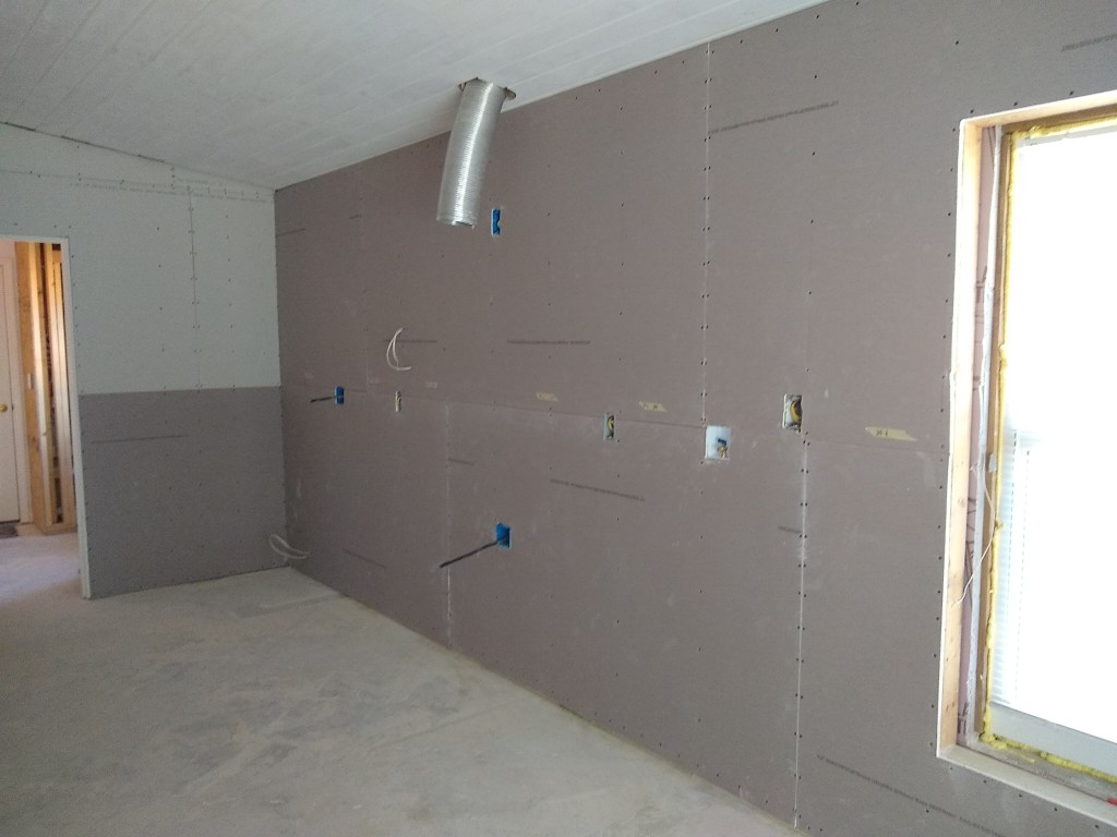
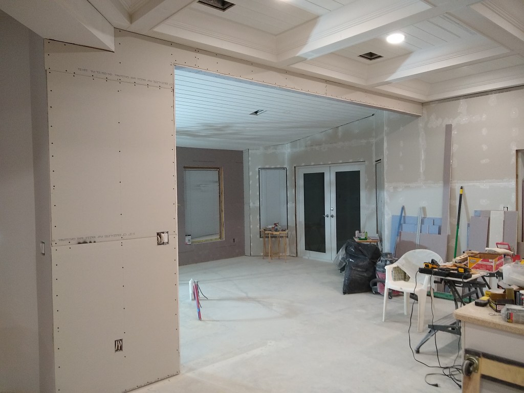
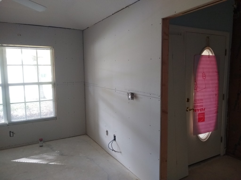
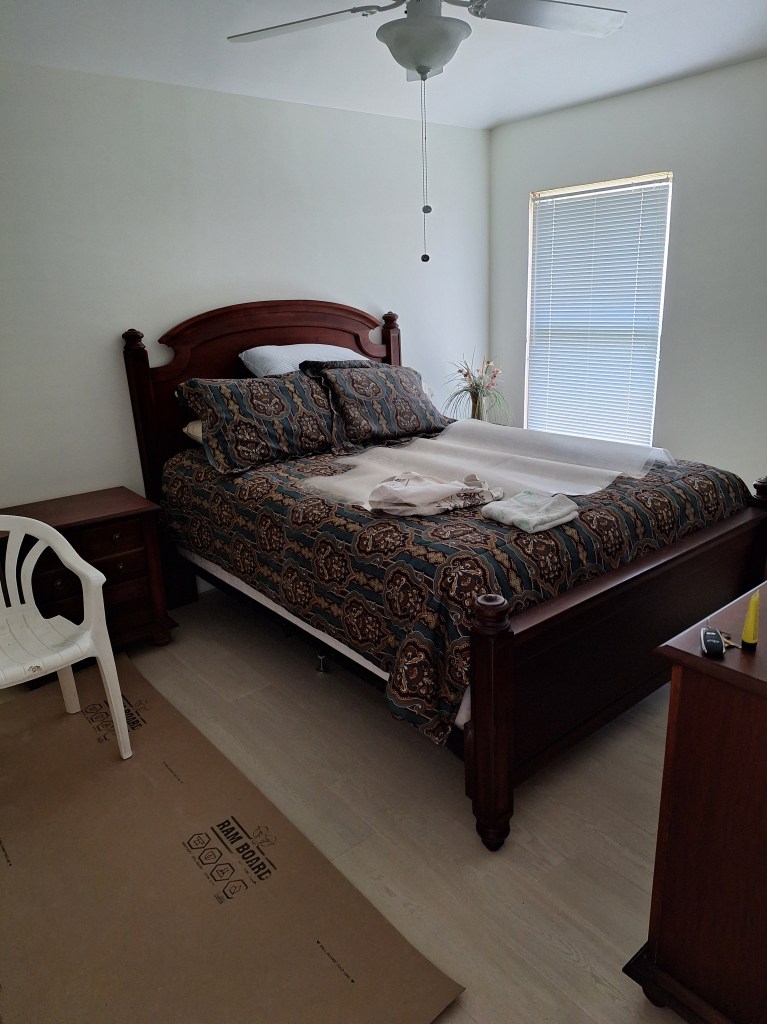
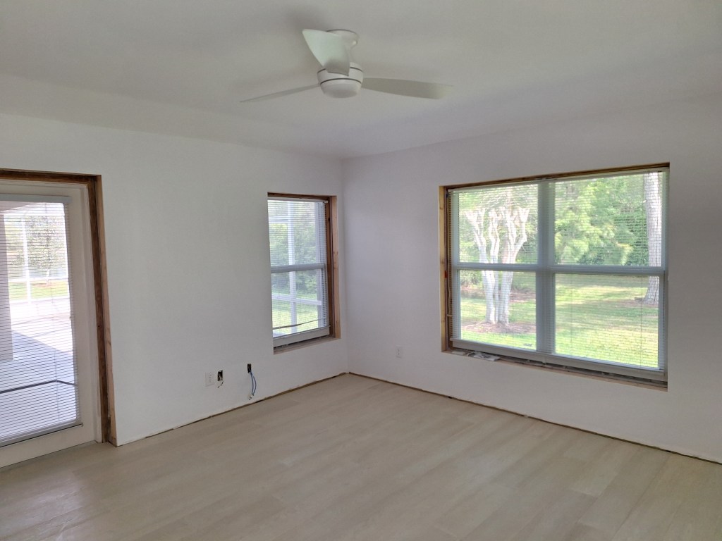
At the end of the last post, the flooring installation was paused as I waited for the extra material to arrive so they could finish the job. Before that, they finished the master bedroom, which took two days, and then started on the office. I forgot to show a picture of the master bedroom before the pause, so here it is now.

End of Day 7, Master Bedroom – from Entrance.
End of Day 7, Master Bedroom – toward Bathroom.

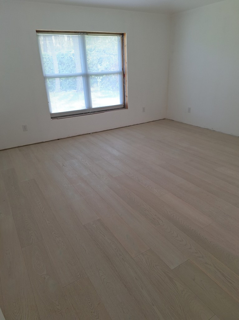
In the image above, notice how on the wall near the window I used two different primers, hence the color difference. I mention this because later I will show the bedroom after I painted it and it is hard to distinguish between the primer and the paint. This was just to provide evidence that the room wasn’t painted before the flooring was installed.

While I was waiting for the additional flooring to arrive, I started cleaning up and organizing the place. Now that most of the flooring was in, I could begin dusting the contents that had been moved out of the bedrooms into the great room. Most things were caked with dust from the many drywall sandings that had taken place. Since that part of the renovation was behind me, dusting the furniture and other items was no longer pointless. It would be nice to work in a relatively clean environment for a change. Also, since I had the time, I cleared the workshop of its contents and scraped the floor in preparation for the return of the installers.

Great Room, after some dusting and reorganizing.

Once the wood arrived, I notified the installers and they showed up a couple of days later to finish the office and workshop.

End of Day 8, Office – from Entrance.
End of Day 8, Office – toward Entrance.

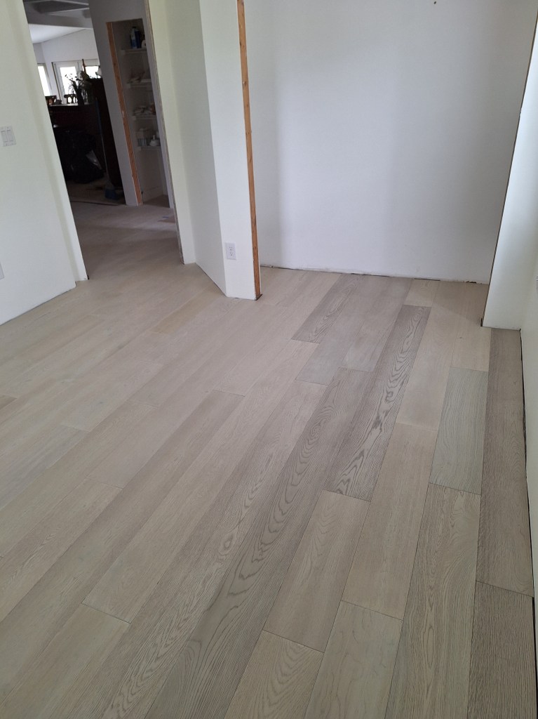
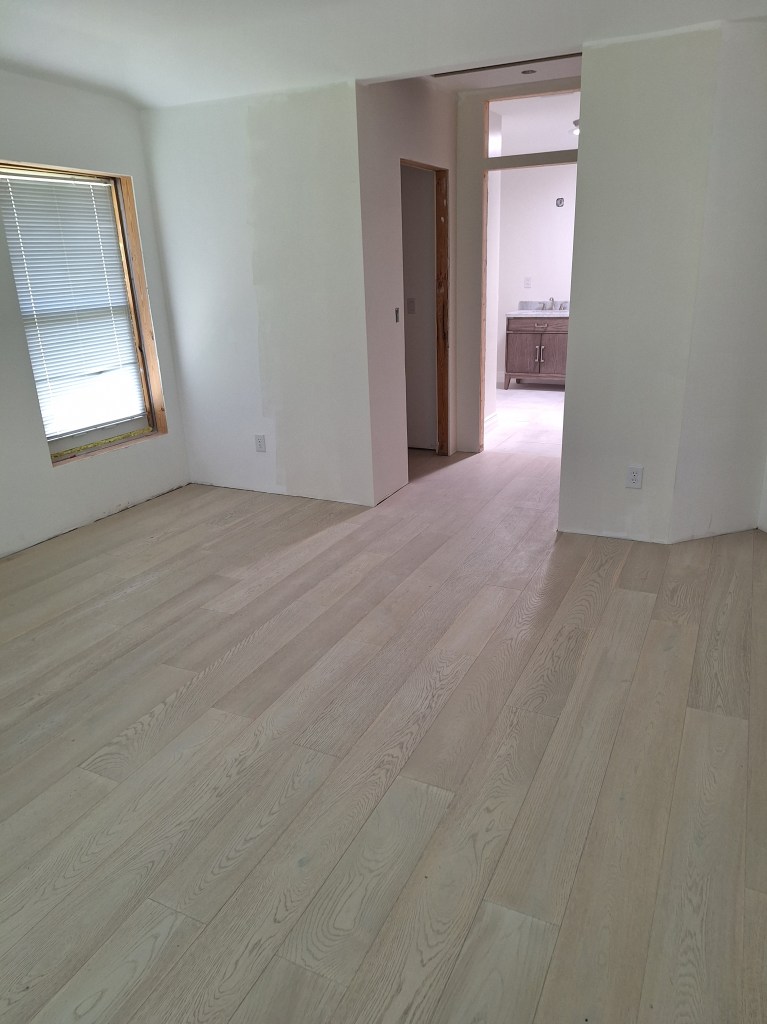
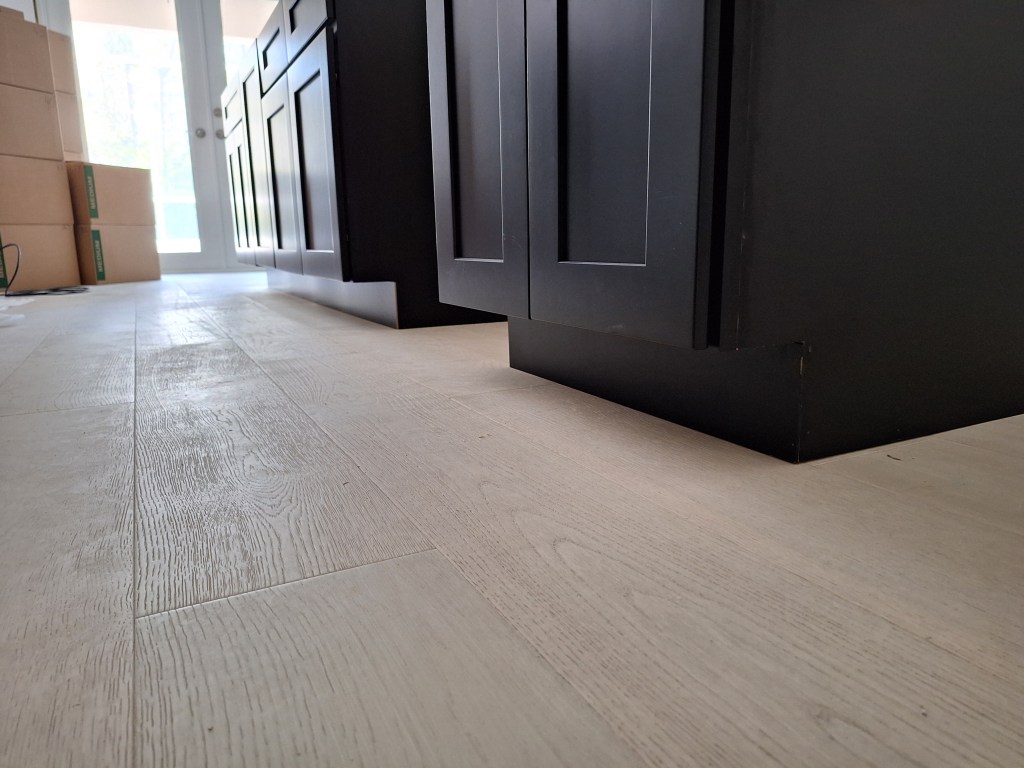
Notice how there is a bit of variation in the wood. The left side was done using the original order, and from about the middle of the room toward the right is where the newer flooring was introduced. This is even more evident when you look at the workshop, which was the last room they did.

End of Day 9, Workshop – from Entrance.
End of Day 9, Workshop – toward Entrance.

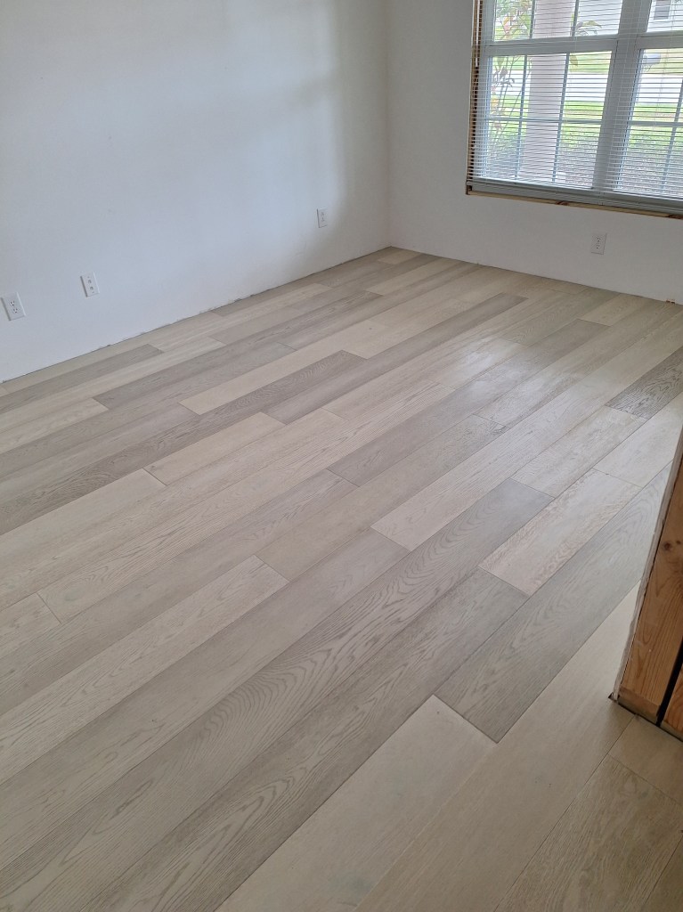
The flooring in these two rooms is far more patchy than the rest of the house. This possibility was taken into account when it became clear that additional flooring would be needed, which is why I asked them to use the remaining material in the master bedroom. Under normal circumstances they would have continued from the guest bedroom and hallway into the office and then the workshop, finishing up in the master bedroom. Knowing that the new material may vary somewhat from the original, if there was going to be any variation, I wanted it to be in these two rooms.

With the flooring installed, I could start to move the things I had dusted back into the rooms, where they would remain dust free, apart from the usual dust one gets.

Guest Bedroom – adding furniture after flooring laid.
Office – returning contents after flooring laid.
Workshop – returning contents after flooring laid.

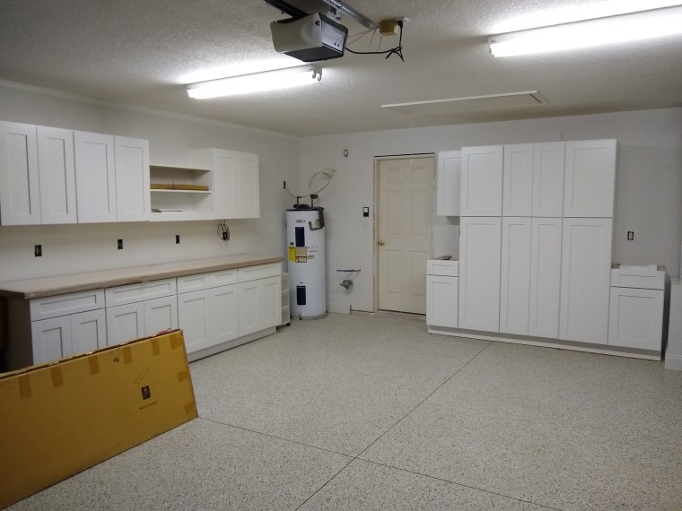
In the workshop, I decided to re-purpose the cabinet that was supposed to be placed on the far side of the refrigerator. Unfortunately, I miscalculated the room I had along the east wall of the kitchen, and this nice little cabinet would not fit. So here is its new home.

Cabinet added to Workshop
New Cabinet with Doors open.

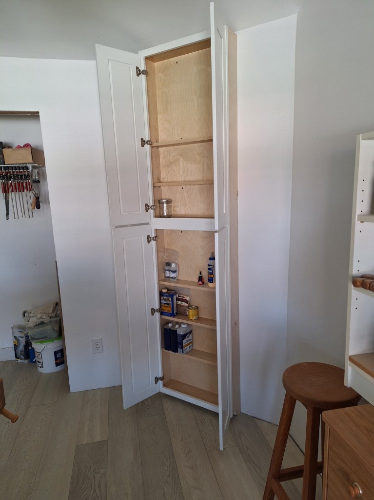
In the kitchen, this would have been great for spices, but here it will serve nicely as a place to store glues, finishes, and maybe screws and other fasteners.

Wiring the kitchen island was my next priority. After completing this I would be able to request another inspection to trigger an extension of my permit expiration date.

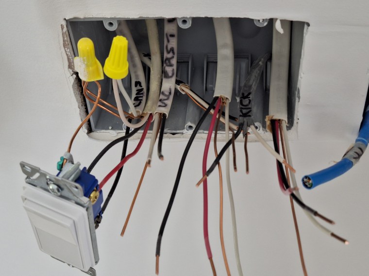
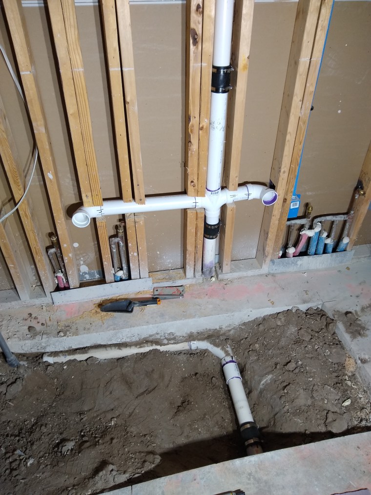
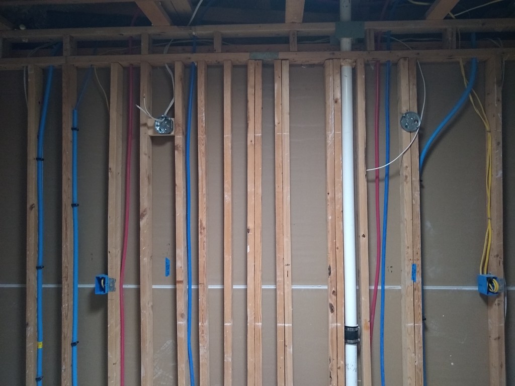
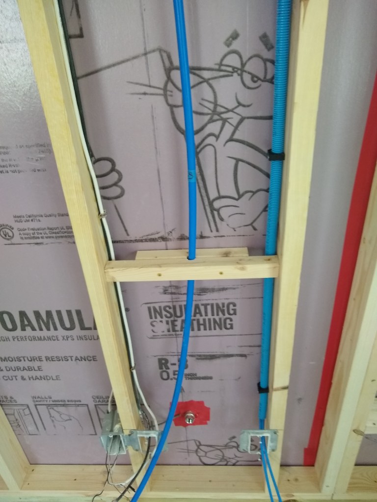
The island has three lines coming into it from under the slab. In the picture below, the wire on the left is tied to the general 15 amp circuit for the kitchen, and will be used for kick lighting. The one in the middle is for the 20 amp GFCI outlets. The one on the right is on a dedicated 20 amp circuit for the dishwasher.

Junction Box in Sink Base Cabinet

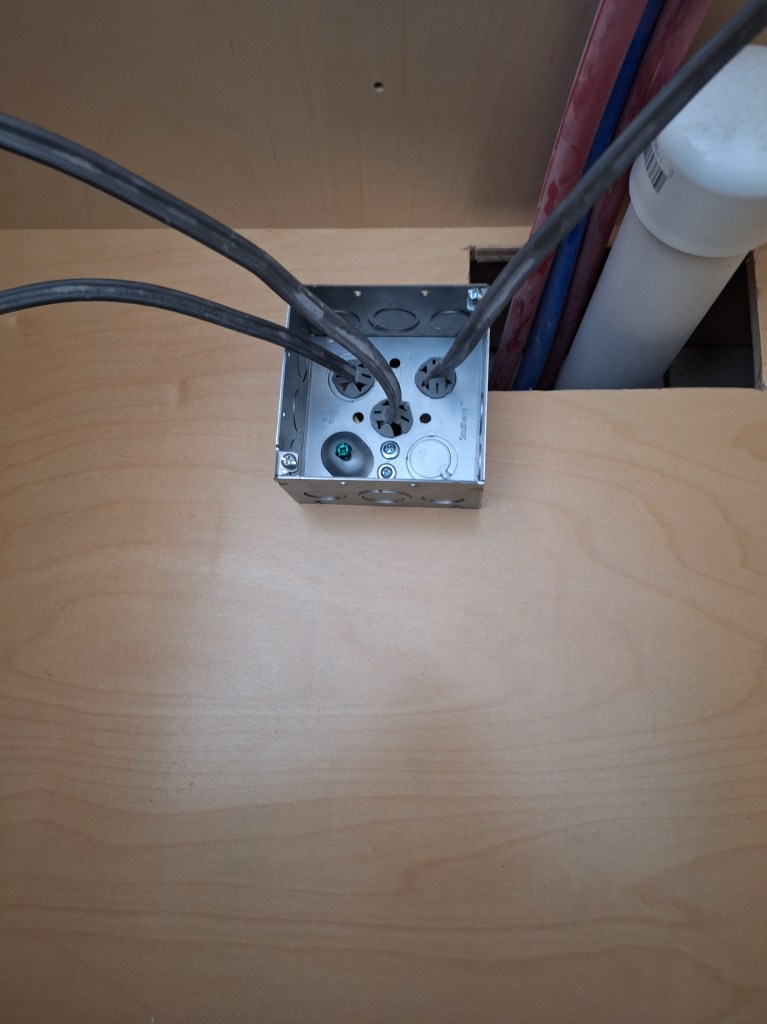
Because these wires are located inside cabinets, they will be subject to damage as items will be moved in and out of them. Consequently, they need to be protected. This is done by using Metal Cased (MC) cable, instead of the usual Romex that is run behind the walls.

Wiring under Sink Base Cabinet

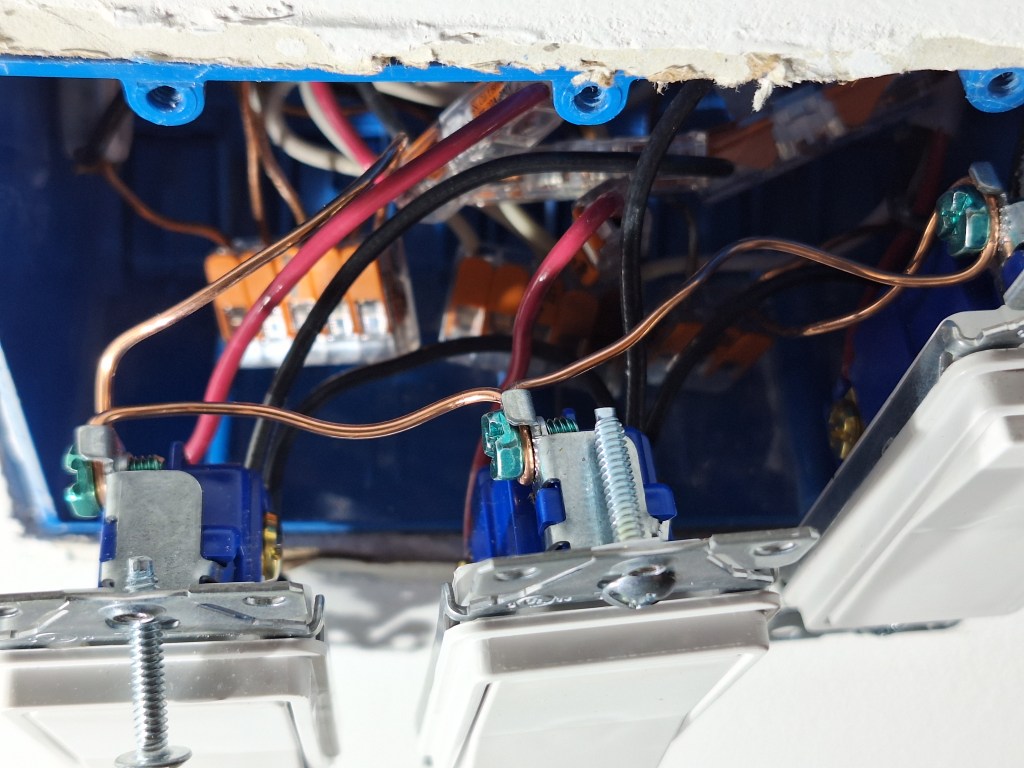
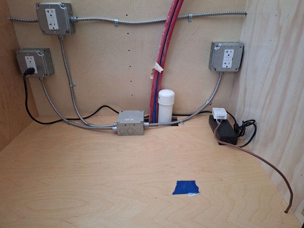
The outlet on the far left is where the power adapter for the kick lighting will plug into. The one just above it is the GFCI outlet. The in-sink garbage disposal will plug into this. It branches out on either side to the two ends of the island where counter top pop-up outlets will connect. The outlet on the right is where the dishwasher will connect. The inside of the junction box on the bottom of the cabinet looks like this inside:

Junction Box Wiring

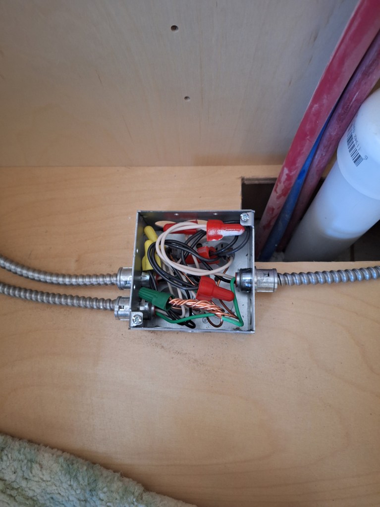
Below I provide a series of pics to show how it all fits together.

Outlet in North End Cabinet to supply power for Counter top Pop-Up Outlets

An MC cable extends from the outlet shown above heading south behind where the dishwasher will go and into the sink base cabinet, connecting to the GFCI wire inside the outlet box, shown below.

Sink Base Cabinet Outlets

At the other side of the GFCI outlet, another MC cable extends southward behind the cabinet where the garbage pales reside.

MC Cable running behind Garbage Cabinet

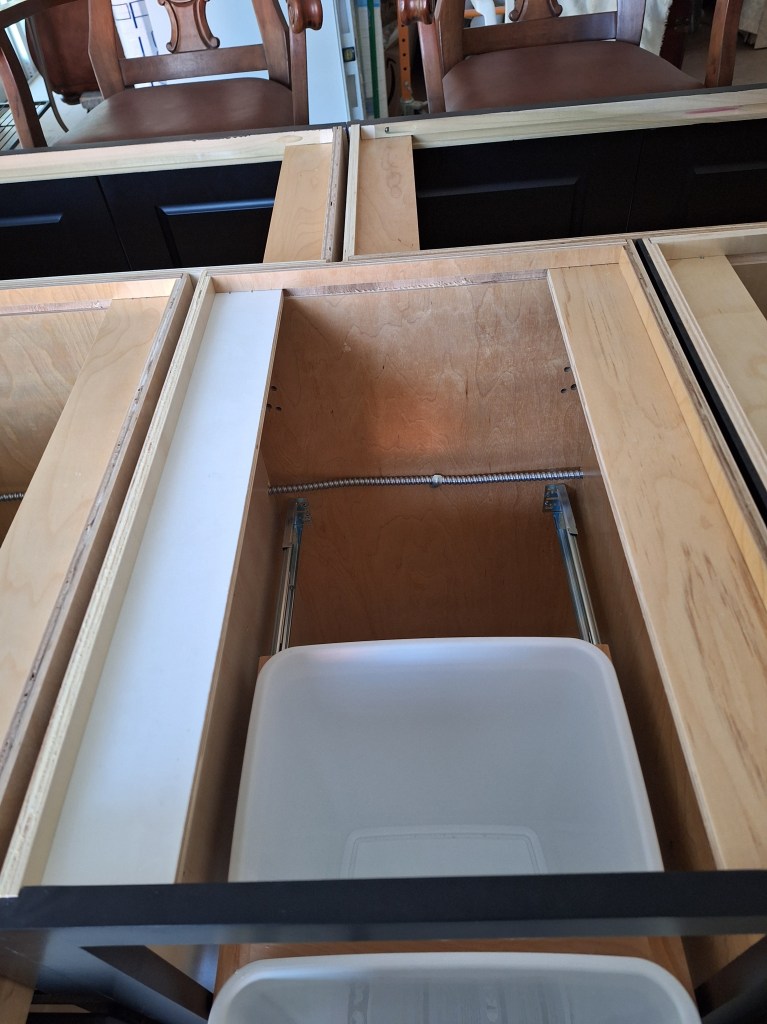
This cable terminates at the second outlet that is in the south end cabinet. It will provide power for another set of counter top pop-up outlets.

Outlet in South End Cabinet to supply power for Counter top Pop-Up Outlets

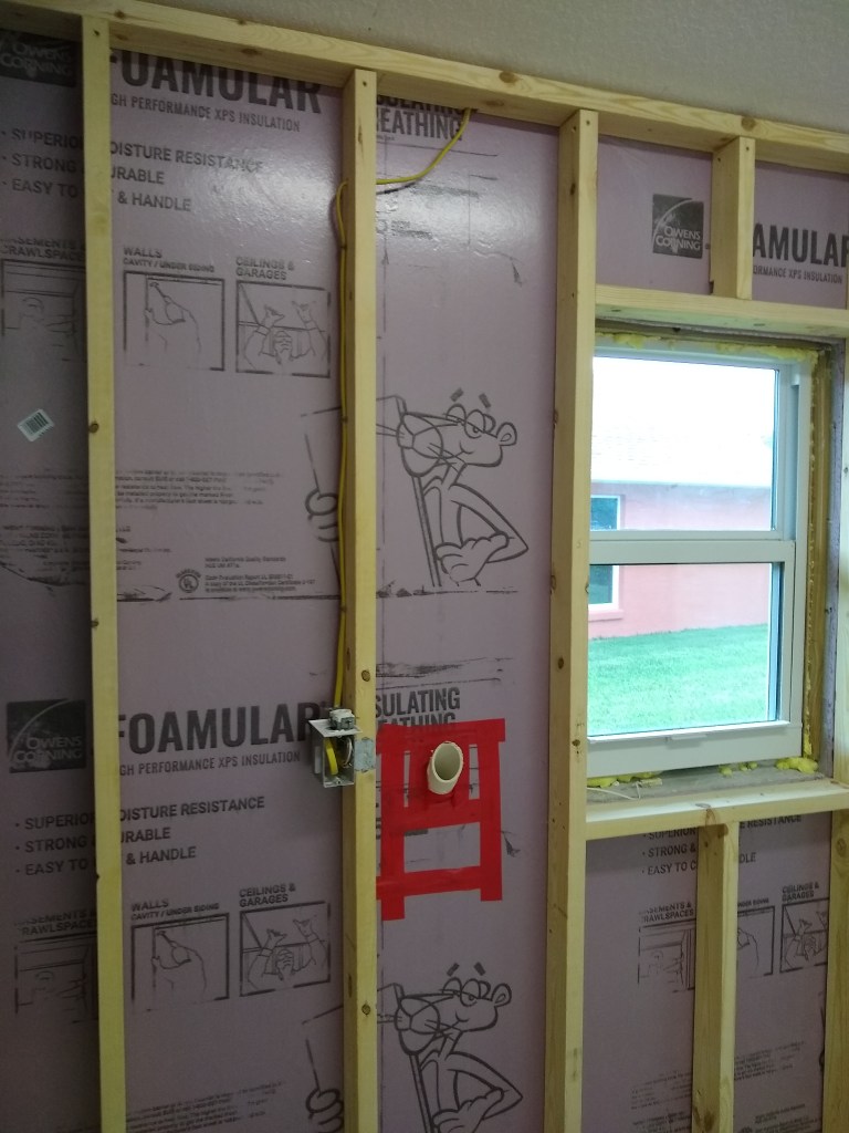
I also installed an outlet at the bottom of the pantry for the kick lighting along the east wall of cabinets.

Pantry Cabinet with new Outlet for Kick lighting.
Pantry Cabinet – new Outlet for Kick lighting, with drawers re-installed.

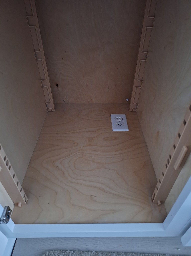
The inspection was performed shortly after, and it was successful. Thus, my permit expiration date is now extended to September.

Since the ends of the island cabinets do not match the color of the cabinets, a 4’x8′ sheet of 1/4″ material is provided so that it can cover those areas. So I cut and shaped it and attached it to both ends. Here is one of the ends.

Kitchen Island – Side Panel added.

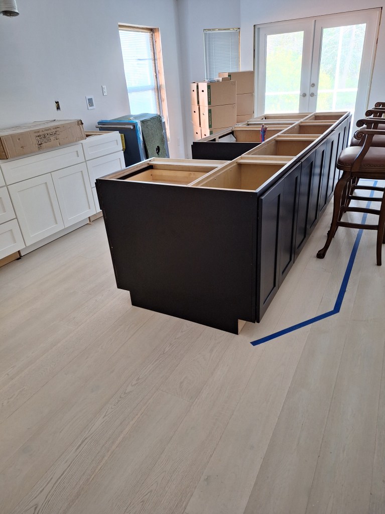
That looks much better. I’ll do the same for the kicks, but only after I understand how I will run the lighting for that area.

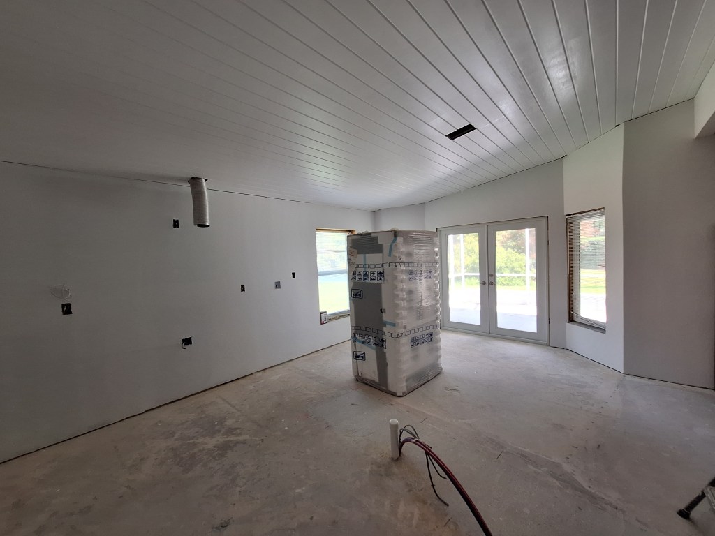
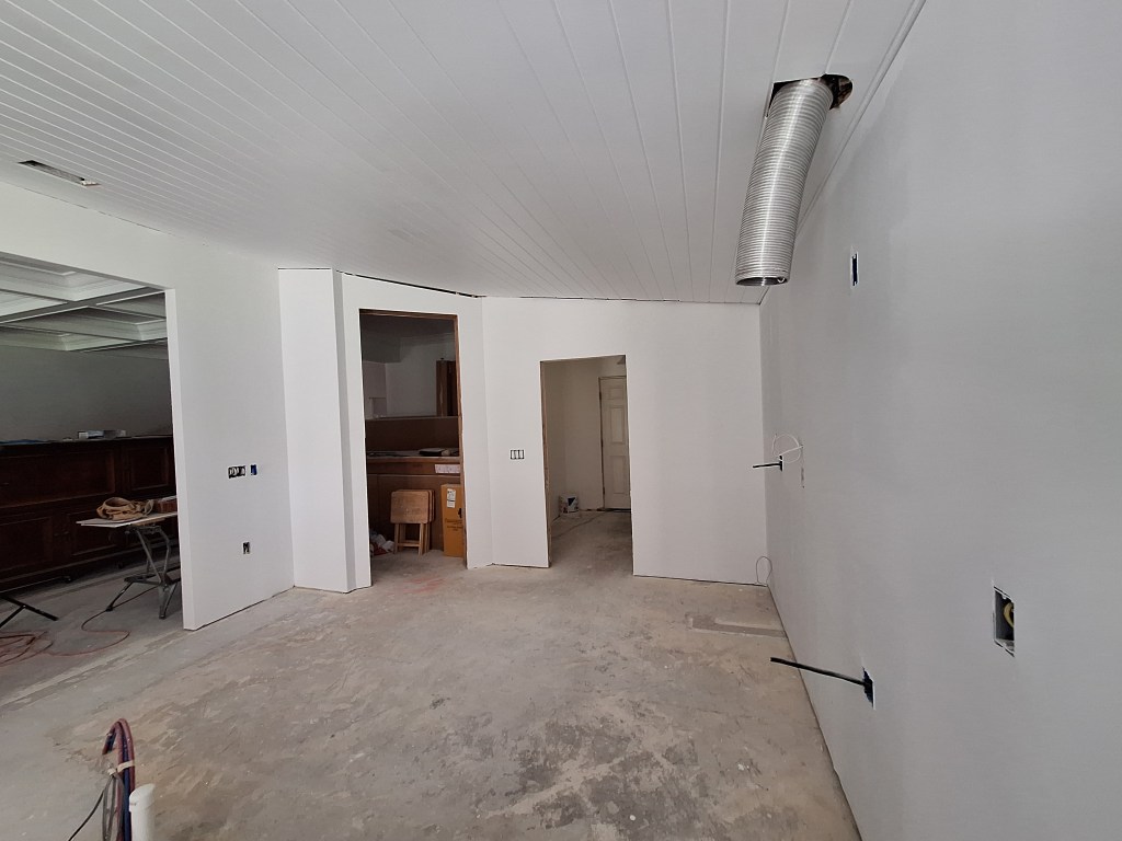
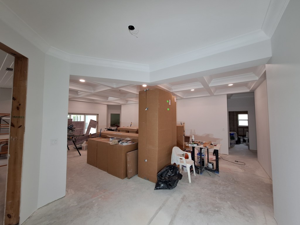
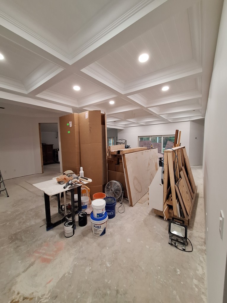
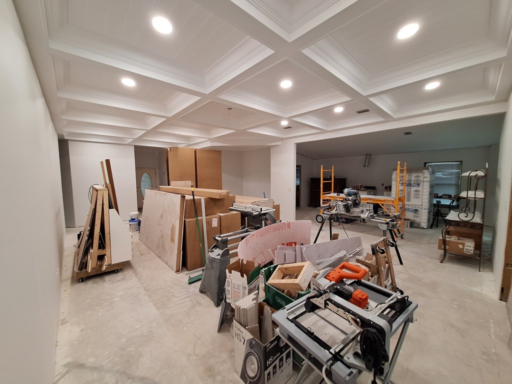
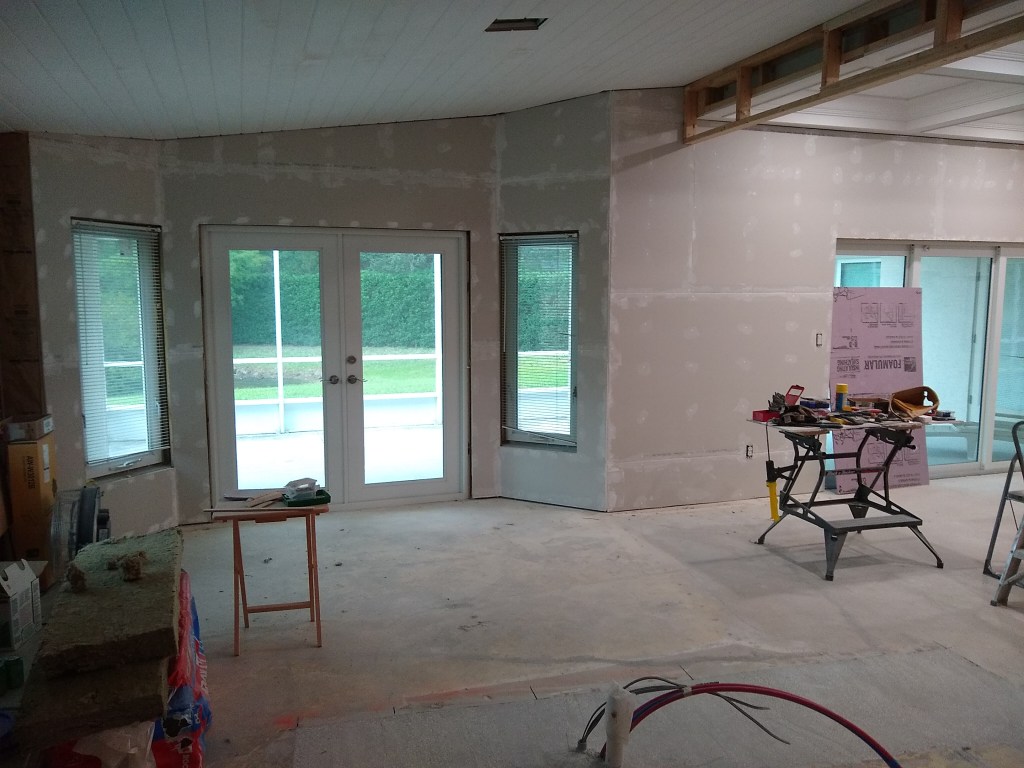
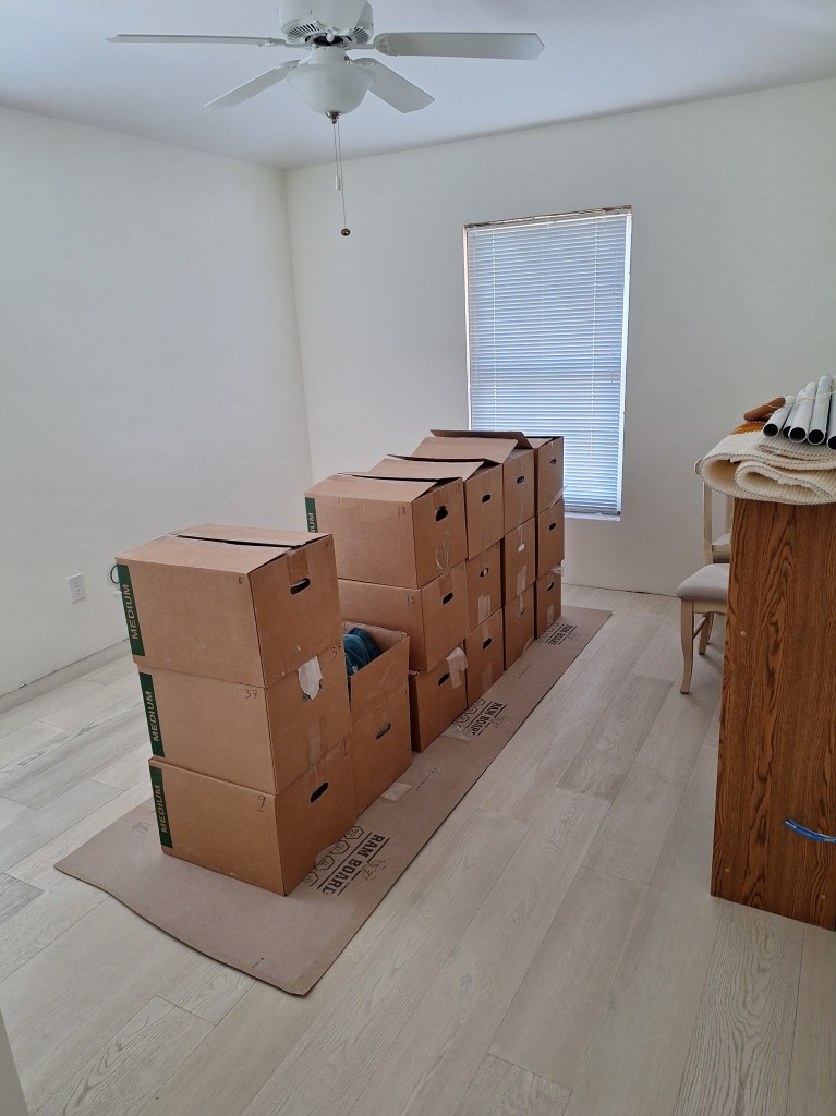
I spent some time researching how to install the kick lighting. After feeling like I understood it and deciding on the approach I would take, I ordered the various pieces. That would take some time to arrive, so I decided to clear out the contents of the great room, which had been holding the contents of the various bedrooms while the flooring was being installed. It was nice to clear that area. With the flooring in and the great room mostly cleared, it made the place look less like a constructions site.

Great Room – from Foyer, after Clearing stored Contents.
Great Room – from Guest Hallway, after Clearing stored Contents.
Great Room – from entrance to Master Bedroom, after Clearing stored Contents.

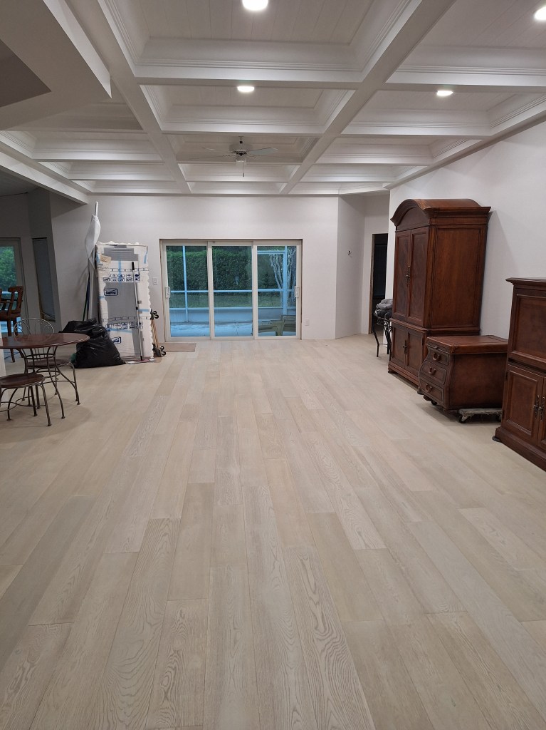
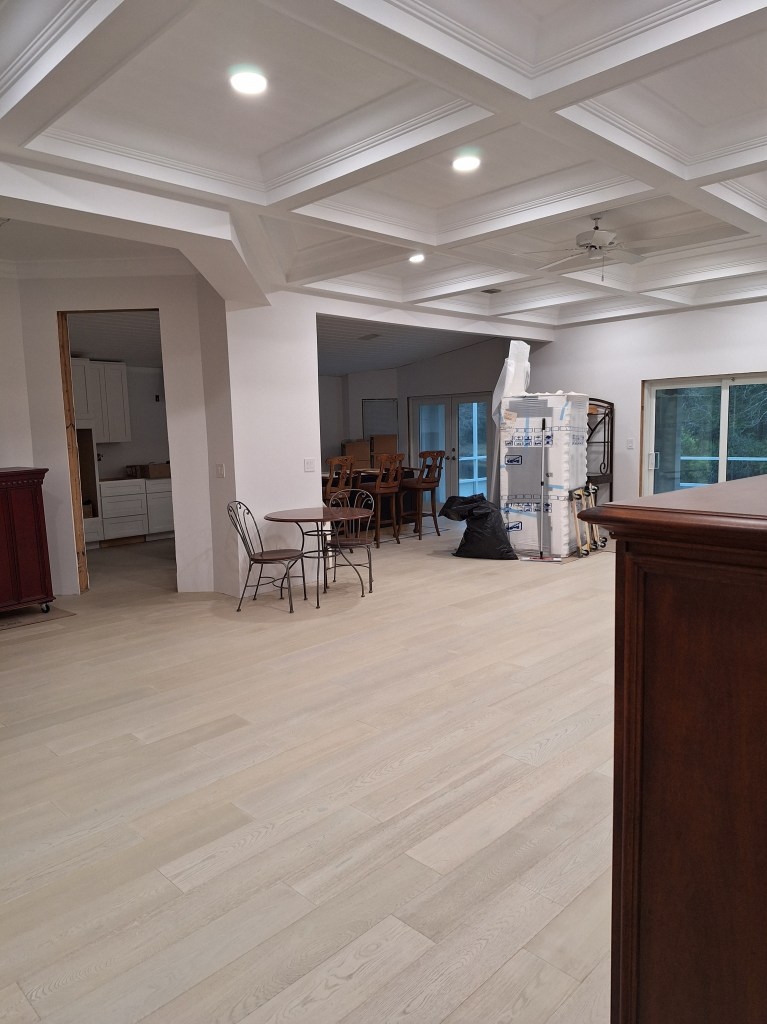
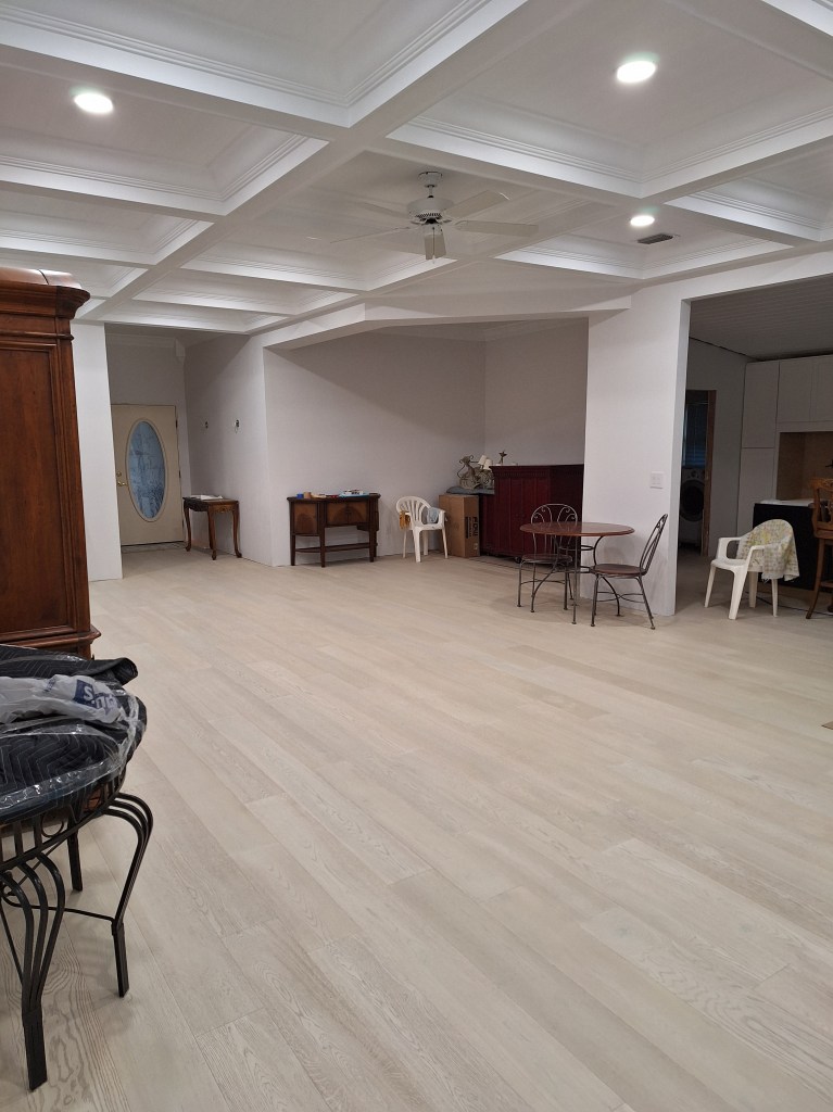
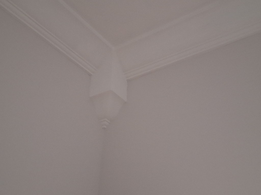
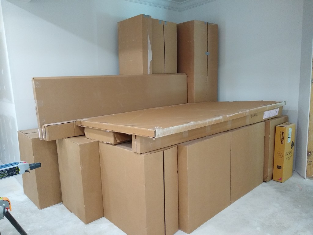
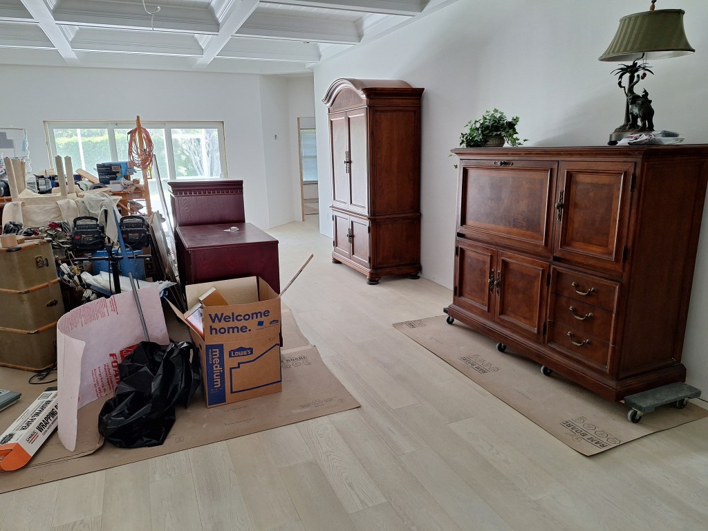
I have a number of items I no longer need and will attempt to sell. I’ve temporarily stored them in the dining room area. The keen observer will notice that I installed the ceiling fan, too. That’s the original one. I think it looks pretty good, so I might just leave it. It will depend on how I intend to decorate the place, which will be a very long way off.

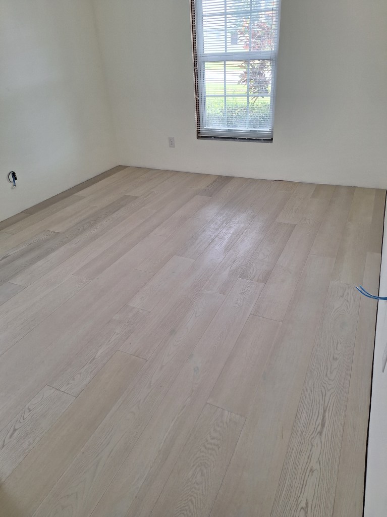
While still waiting for the kick lighting parts to arrive, I painted the master bedroom. The final room to be painted. The ceiling in that room was painted long ago, but the walls had only been primed, so I would give it two coats of the same paint I used for the great room.

Master Bedroom Painting Complete – From Northwest Corner
Master Bedroom Painting Complete – From Entrance

I hope you noticed the new fan/light I installed. I was going to install the original fan, which didn’t have a light. I wanted to have an overhead light in this room, so I opted for this. I really like it. It is controlled by a remote control, which allows me to vary the fan speed and dim the light. Very nice! I may replace the others with this style, but that is a very low priority so it won’t happen anytime soon.

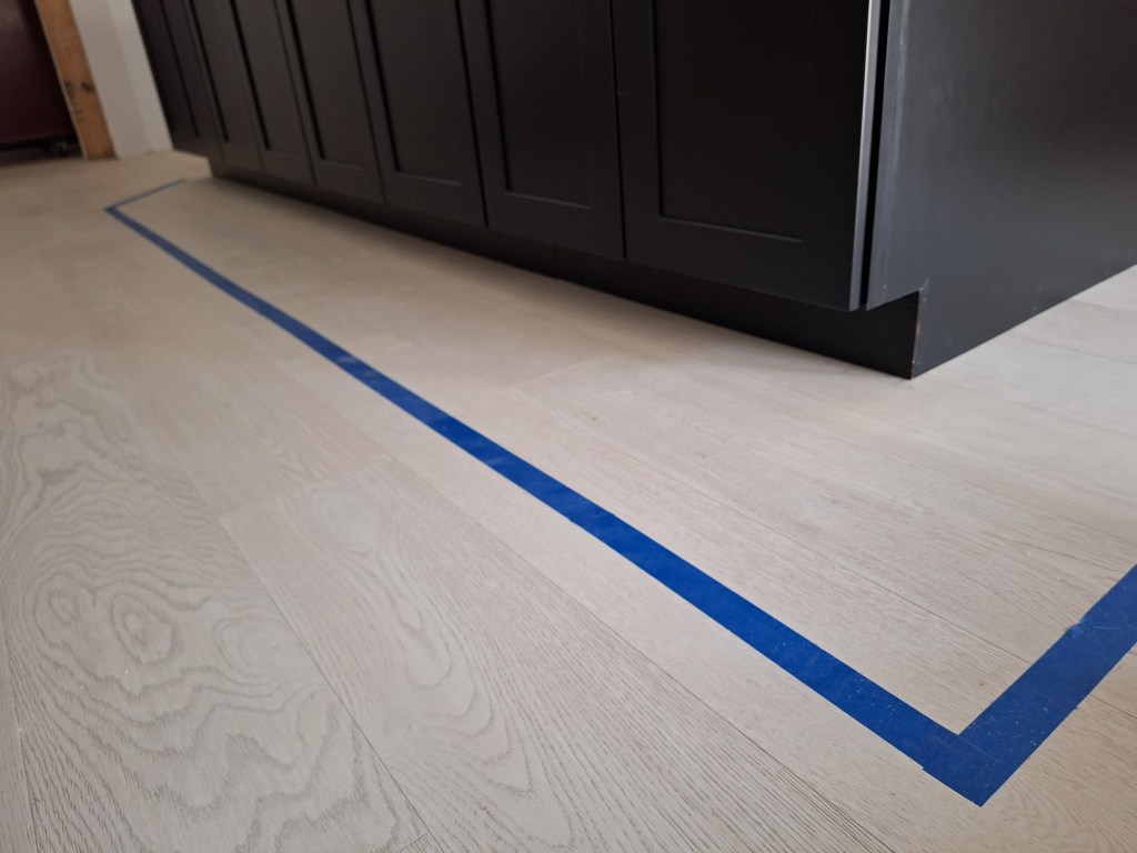
The parts for the kick lighting arrived around the time I finished painting the master bedroom, so I got to work on that. The first thing I did, was install the kick plates. Below I am showing the back of the island from the north side. The gap between the cabinets is where the dishwasher will go. Keep this in mind as I discuss the sequence of runs of kick lights I will install.

Kick Plates installed along Back of Island

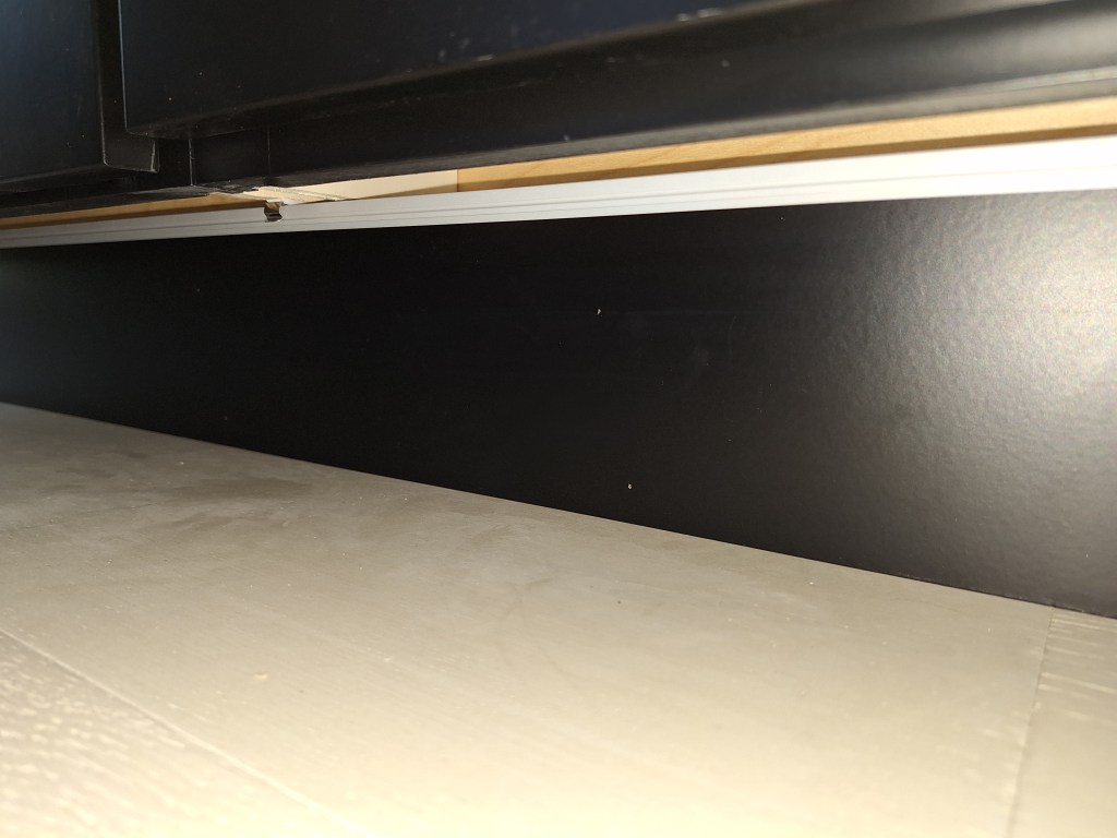
Below I show the kick under the front of the island from the south end.

Kick Plates installed along Front of Island

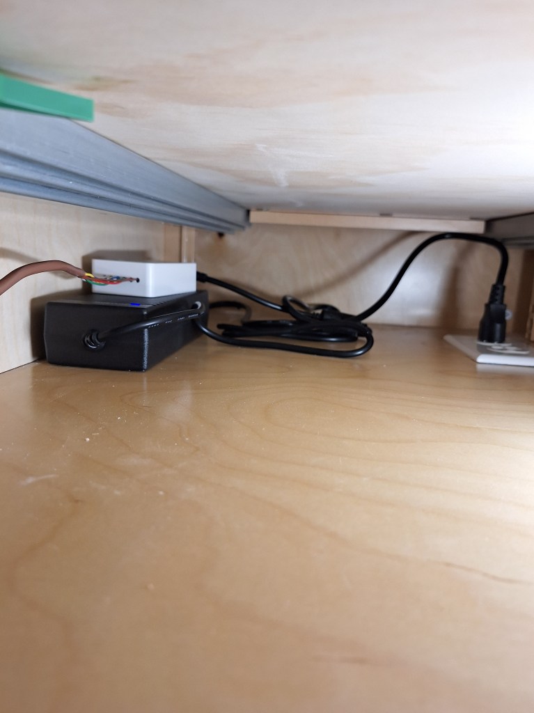
The kick lighting is controlled by a switched outlet under the sink. Since the LED lights require 12 volts DC, a power adapter (the black box) is required to convert from 120 volts AC to 12 volts DC. A controller (the little white box) is plugged into the power adapter to control the LED lights, which can produce a whole spectrum of colors. This controller is WiFi enabled, so at some point I will be able to modify the colors using an app on my phone. The power adapter and controller for the kick lights will be located in the sink cabinet, which is on the back side of the island to the left of where the dishwasher will go. I ran the wires from it to the front of the cabinet and down a hole I drilled to the kick area.

Kick Lighting Power Adapter and Controller in Sink Cabinet
Closeup of Power Adapter (black) and Controller (white).

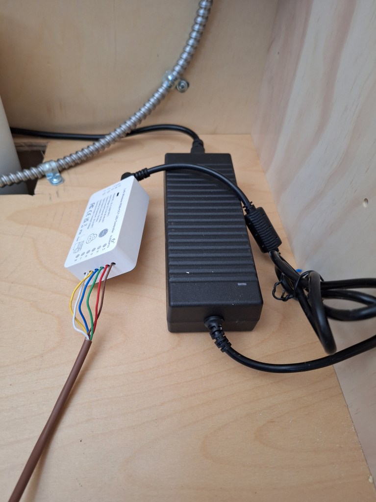
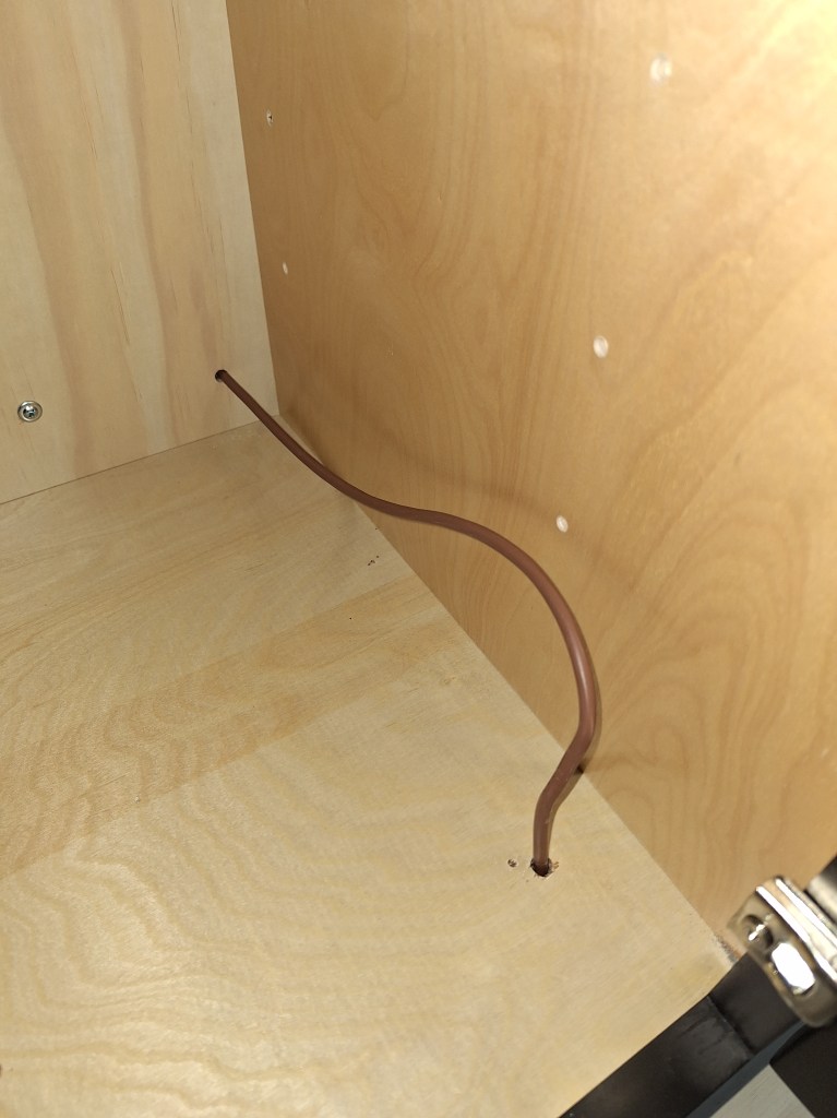
The brown wire that is connected to the controller interfaces with the LED strip under the kick, which I will show later.

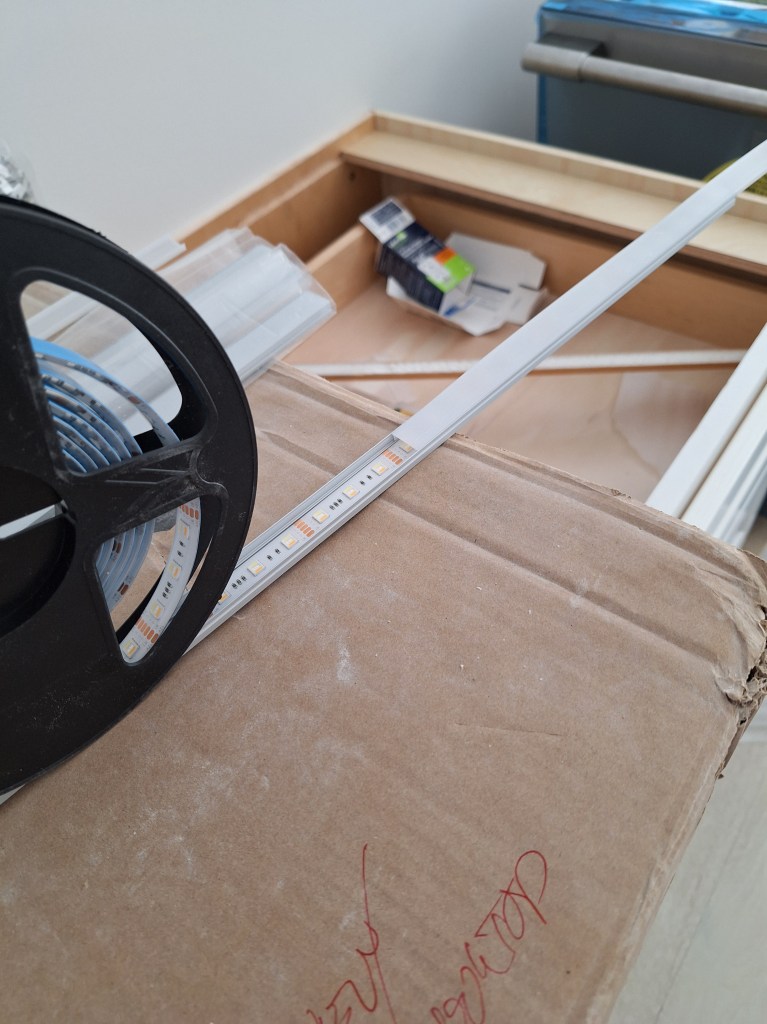
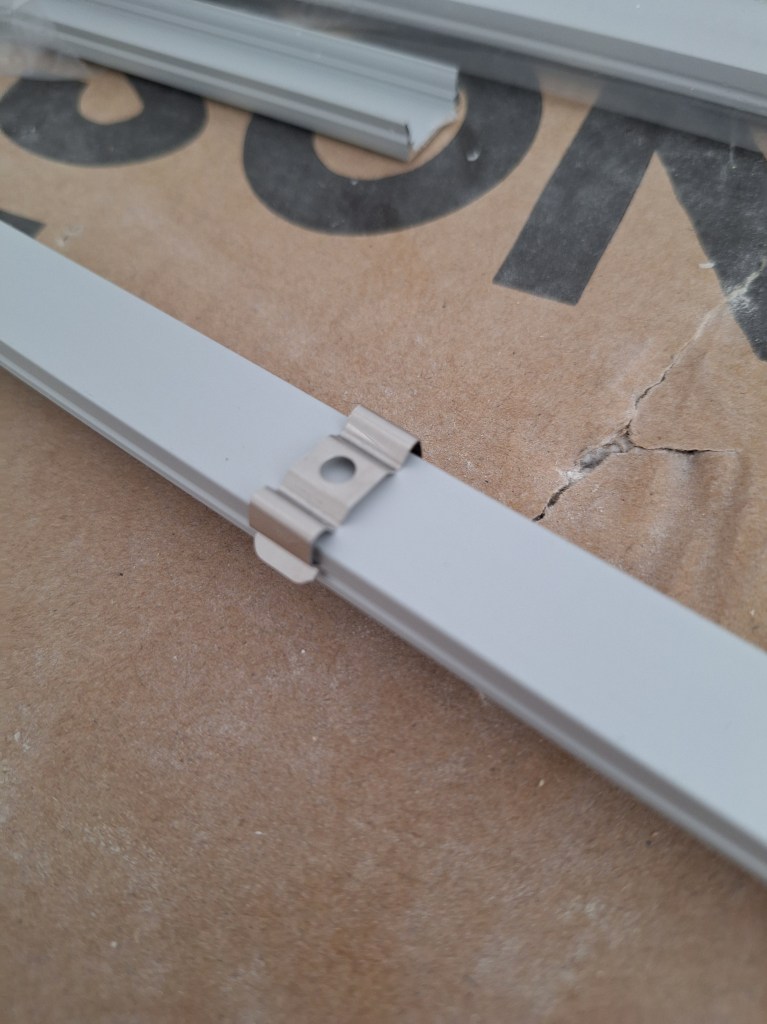
The LED lights come in a roll and can be cut at designated areas where it can be terminated or connected to other runs. The light strips have an adhesive backing and are inserted into channels I attach to the underside of the kick space.

Lights in Channel

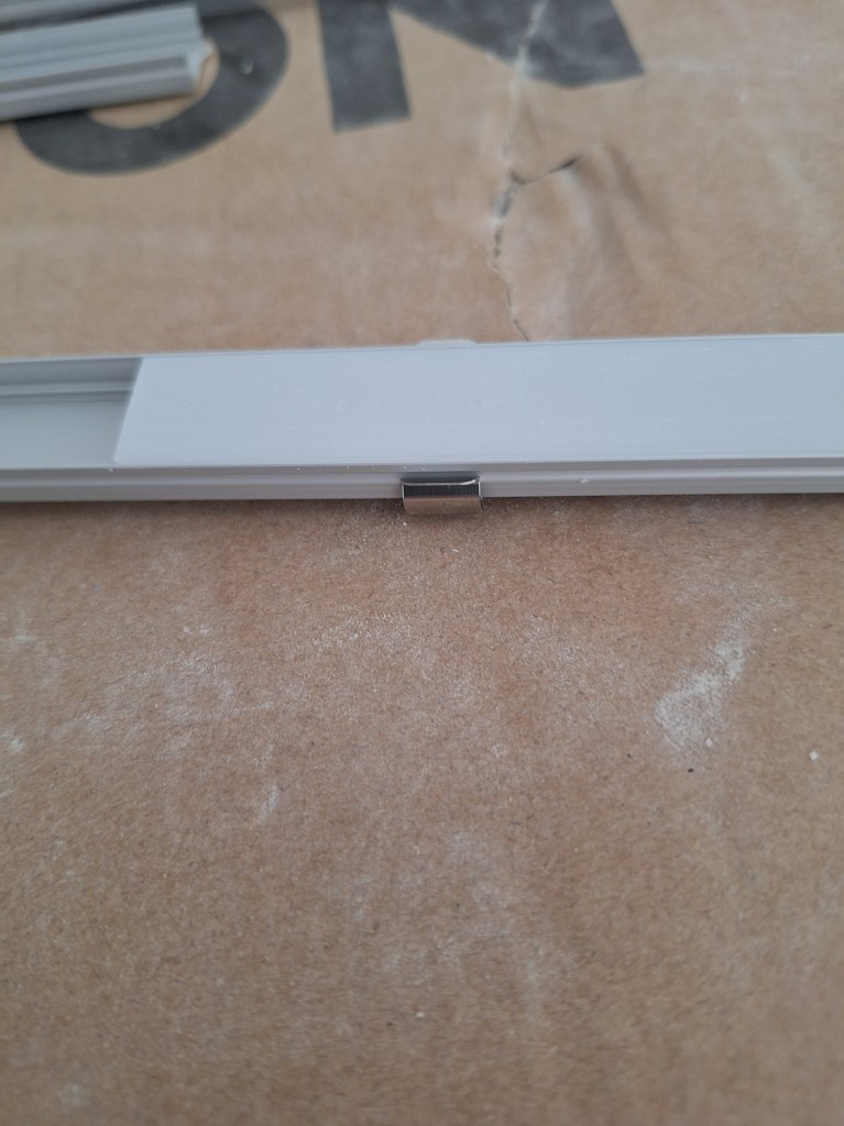
The light strip is covered by a diffuser, as shown below.

Diffuser that covers the Light Strip inside the Channel

To support these channels, small clips are used.

Mounting Clip on Back of Channel
Mounting Clip as it appears on Front of Channel

The mounting clips for the channel can be screwed into the bottom of the cabinet wall panels, but in order to hide the channels from sight when looking at the island from north and south ends, I added blocks a few inches in from each end.

Additional Blocking for Channel Attachment

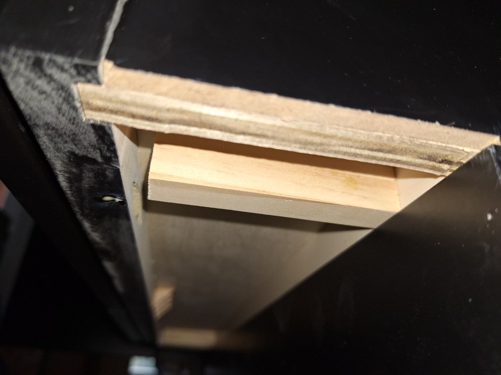
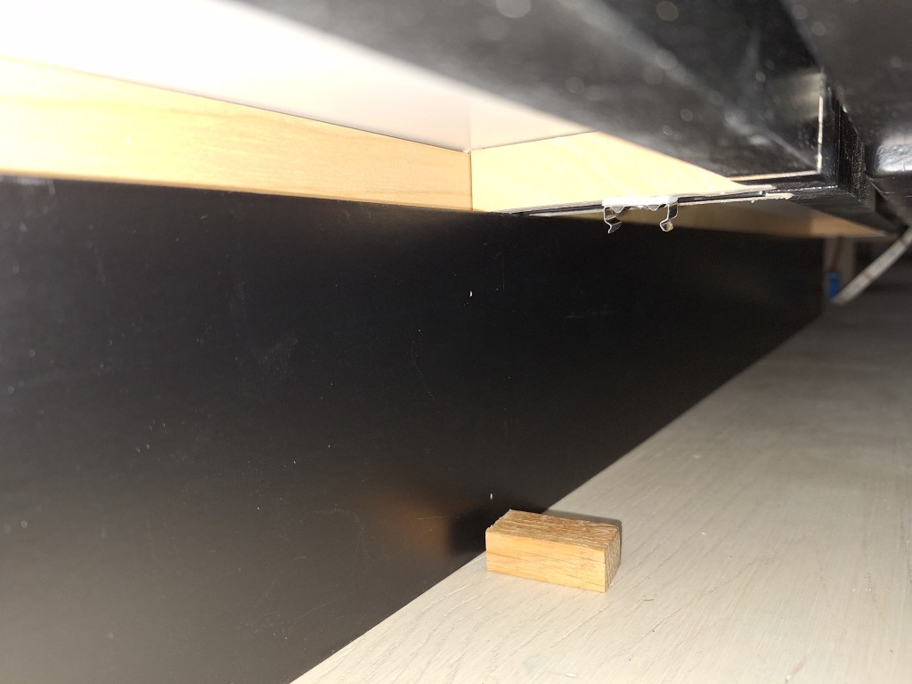
I attached these small blocks using a combination of super glue and wood glue. The wood glue provides the strongest hold, but takes some time to cure. So I used the super glue to get an immediate hold, serving as a clamp, so to speak, as the wood glue cures. Six of these blocks were required in total. Below I show one of the clips attached. I used double sided tape to put it in place before securing it with a screw. The small piece of wood you see on the floor was used as a spacer to make sure each clip was positioned the same distance from the kick plate. It was a chore installing these things. I had to use a very short screwdriver as I lay on my side trying to work the screw into the wood.

Channel Clip Secured

Here is the channel in place.

Channels Attached

And below is how the lights within the channel are connected to the controller under the sink.

Connection Under Sink Cabinet

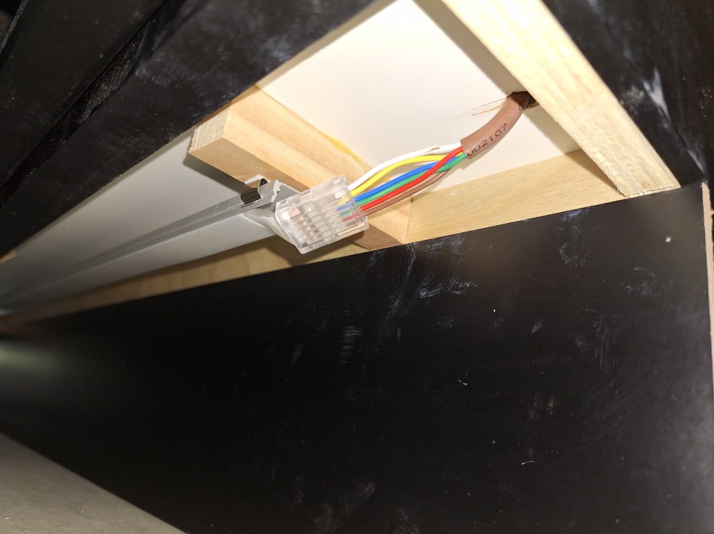
To add the lighting I wanted around the island would require three separate runs, each connected by wires I would feed through the cabinets connecting the runs on the back of the island to the front. The first run would start from the sink cabinet and terminate at the south end of the island. The second run would pick up from the first at the south end of the island, but on the other/front side (facing the great room) and run the entire span of the island. Below I show the wire that is connected to the end of the first run and through the back of the end cabinet.

Wire to connect First Run to Second Run

It emerges at the back of the end cabinet at the front of the island, where it dives down into the kick area underneath and is connected to the second run in the same way the first run was connected to the controller (shown above).

Wire from Back Cabinet to Front Cabinet

The third run would be a short one, starting on the north end and terminating where the dishwasher will go. The second run is connected to the third run in the same way we connected the first and second runs. Essentially, I am wrapping around the island from one side of the dishwasher and terminating on the other side of the dishwasher.

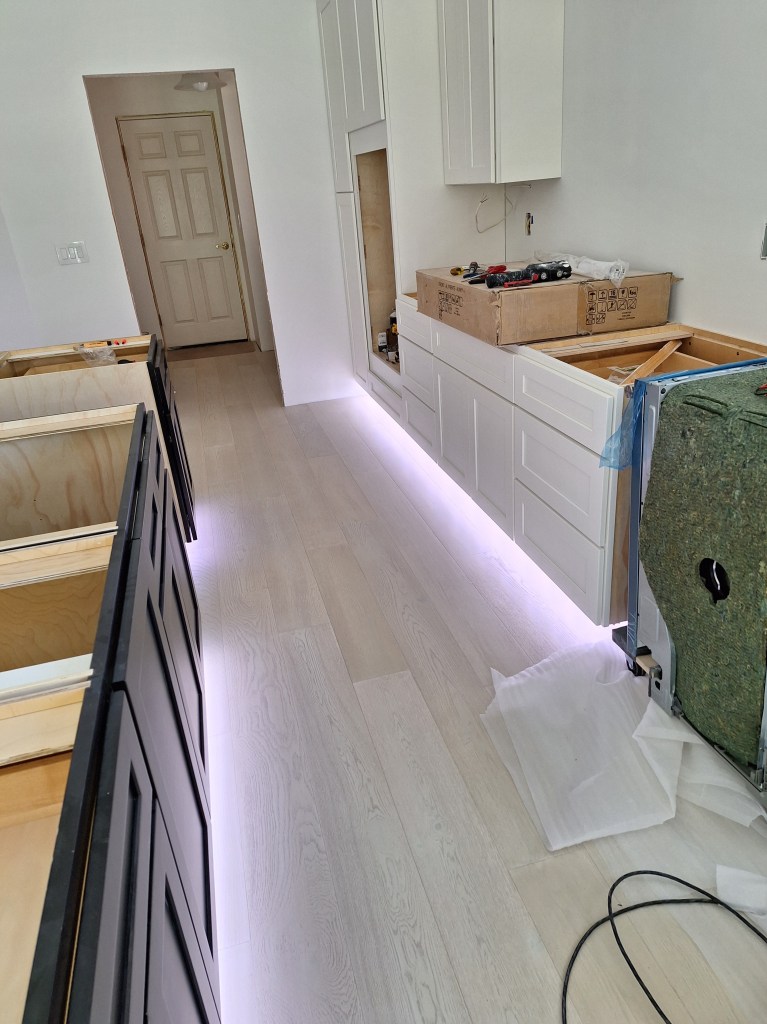
Here are the various runs illuminated.

First Run Complete
Second Run Complete
Third and Final Run Complete

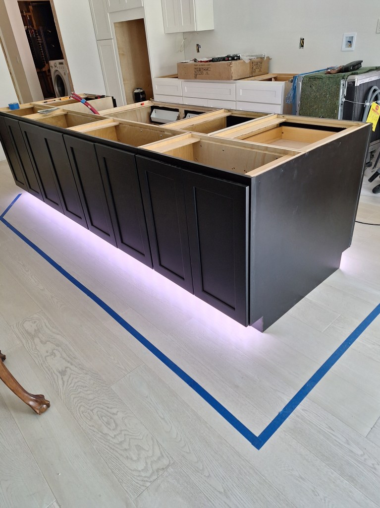
I think this looks pretty good. I still have some work to do to secure and protect the wiring in the cabinets. I have some ideas about how to do that, but will get to it when it suits me. Next I tackled the kick lighting under the white cabinets.

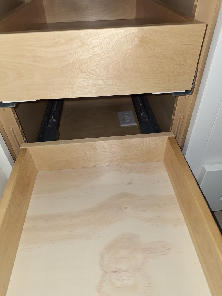
The kick lighting for the cabinets along the east wall of the kitchen was much simpler, as it consisted of only a single straight run. The power adapter and controller were placed at the bottom of the pantry cabinet.

Adapter and Controller in Pantry Cabinet – Drawer Removed
Adapter and Controller in Pantry Cabinet – Drawer Returned

Here is the final result.

Kick Lights Illuminated along East Wall Cabinets

During this time, I ordered another cabinet that will go above the cook-top and support the exhaust fan. After some thought, that seemed to be the best approach, which I’ll discuss when I show it. I also ordered an additional refrigerator side panel since that nice little cabinet I put in the workshop would not fit. Those items are supposed to arrive in mid to late April. Once they are in, I can start to take steps toward getting the counter tops. More on that in the next post.

Hot Water Tank Installation and Major Painting – June/July 2024

While waiting for the shower wall tiles and extra floor tiles to arrive, I decided it was a good time to hook up the hot water heater and install a utility sink in the garage. My original plan was to use the existing hot water heater, since it wasn’t that old. Here is the only shot of it.

Existing Hot Water Heater

This was a 50 gallon hot water heater that was in place before I started this project, when I drained and disconnected it, with the intention of reusing it. Although it was only a few years in use, I removed the pressure relief valve that is located on the side of the tank to have a look at it and replace it (something one should do from time to time). I saw quite a bit of scale on it, which caused me to rethink whether it was a good idea to reuse the tank. I did not want to go through the trouble of hooking it up only to replace it not long after. So I purchased a new one. This time I got a 40 gallon tank, since that should be plenty for my needs and those of any guests I might have. Here it is installed.

40 Gallon Tank Installed

Rather than use 90 degree bends to feed the tank, I used 45 degree connectors for a straighter run. I think it looks a bit odd, but that’s okay with me. An inspection will reveal whether any changes are required. At this point it is working and I have hot water again.

Closeup of the Hookups
Pressure Relief Valve Hookup

In the image above, you can see that the pressure relief valve is connected to the existing pipe that takes the water outside the garage.

With that done, I installed a new utility sink beside it.

Utility Sink Installed

I had intended to reuse the utility sink that came with the house; the one I relocated to the guest bathroom. However, since it was my only source of water, I did not want to disconnect it without having an alternative, so I kept the existing one in place and bought a new one for the garage. I opted for a slightly smaller tub since I am limited in space between the hot water tank and the door (there is still trim to be added around the door). The existing utility sink is 20″ wide and this new one is 18″ wide.

Front View

I think the smaller size was appropriate, as it tucks in nicely without looking too crowded. Here is a shot of the hookups.

Sink Hookups

Notice how the hot and cold lines cross each other. This was a funny little mistake I made when bringing those lines through the wall into the garage. On the other side of the wall they are oriented correctly (hot on the left, cold on the right). I didn’t realize at the time that it would be backward on the other side of the wall. No big deal, and I had a chuckle over it once I realized.

The sink has not yet been fastened to the floor. As with the hot water tank, this will need to pass inspection, which I haven’t arranged yet. I don’t want to secure it to the floor in case the inspector wants me to make changes. So I’ll have to be careful not to jostle it, which can damage the drain connections. In the meantime, it is nice to have hot water and an alternate wash basin to use.

After this was completed, I contacted the place where I purchased my shower wall tiles to get an idea of when they would arrive. To my surprise, it was going to be at least another week, so change of plans. I decided to start painting the ceilings in the great room, foyer, and guest hallway.

These areas had some intricate details, so I decided to use a brush to paint them. When applying the primer, I used both a brush and small roller, but to get a consistent finish, I would use only a brush, which made it a lengthy process, especially since I applied two coats. I used a high quality latex paint with a matte finish – Behr Dynasty Ultra White.

My shower wall tiles arrived after I completed the painting of the ceilings, so I picked them up and set them aside. The master bathroom would have to wait. Having started the painting process in the great room, I decided to push on and paint the ceiling and walls in all adjoining spaces. This meant I would paint not only the great room, but also the dining room and kitchen.

The ceilings in all these spaces would be the same color (Ultra White). The walls in these areas would also be painted, but a slightly different shade of white. Originally I tried the color my designer recommended, which was a light gray – a color match of the Sherwin Williams Quick Silver. I applied it in the foyer to test it out. The next day I decided I did not like it. I expected it to be a light gray, but It had a hint of blue in it, which I did not want, Sorry, I didn’t take a picture of it. I really should have. Anyway, I considered making the walls the same color as the ceiling, but wanted some contrast, if only slight. So I opted for Behr’s White color. Not so white as Ultra White, but still white. I want the house to be bright. Here is a shot of the foyer so you can see the difference. It’s subtle, but present.

Foyer – Ceiling and Wall color contrast.

I really like this color for the walls. It just feels right.

In the kitchen I started with the ceiling (as one should). Since it is a tongue and groove ceiling, I used a brush to paint the entire ceiling. I wanted to make sure the paint was applied to all nooks and crannies. Consequently, this took a long time to apply and was not fun. I applied two coats, as usual. However, after the second coat I was not pleased with the results. You could see a lot of “roping” (i.e., brush strokes). I thought the paint would level out, but it didn’t. Here’s what I was left with after all that work.

Kitchen Ceiling – Roping after brushing on Paint.

This is all well and good if you’re going for the hand painted look, but I wanted a more polished look. So I decided to applied a third coat, but this time using a roller. Having used the brush to ensure all the seems were properly painted, all I really needed to do was smooth out the flat areas, so I figured a roller would do the trick. It did! And here’s the result.

Kitchen Ceiling – After Rolling. Much better!

That’s what I was looking for, and I was very pleased with the result. Note that I will add crown molding between the ceiling and walls, but only after the kitchen cabinets are in. They will dictate where the crown ends, so the crown molding must wait. Because I need the cabinets to be in before installing the crown, it also means the floors will be in (the cabinets will sit on top of the wood flooring), so when I come to painting the crown, drop cloths will be needed to protect them. Something I don’t have to worry about at this stage. It’s nice to be able to paint without concern about dripping paint on the floor.

Here are a couple more views of the kitchen where both the walls and ceiling are painted.

Kitchen – Southern View.
Kitchen – Northern View.

Not that it is noticeable in the pics above, but I did not paint the walls where the cabinets will go (from where the vent is hanging down and to the left of it), for obvious reasons. They were primed, but that’s all. It gives you an idea of how close the wall color I picked was to the color of the primer. There is a difference, but it is small.

Also notice how, other than the refrigerator, I had to empty the kitchen in order to paint. That was not such a big deal because of the mobile bases I added at the beginning of the year (see the post from January). So I’m glad I took the time to do that. After the painting was done in the kitchen, I moved everything back in, freeing up space in the great room for the contents of the dining room, which was the next area to be painted. The dining room was where I stored all the kitchen cabinets. You can see them in the image above. They were moved one at a time into the great room. No mobile bases for them, so that was a bit of a chore.

Here are some shots of the dining room fully painted.

Dining Room – Ceiling and Walls Painted

In the last image above, you can see where I located the kitchen cabinets in the great room. You can also see in two of the images above that I have not yet installed a light fixture in the dining room. The wire hanging down is hooked up to the switch on the wall, so it’s ready to go, but having that light fixture in place is not really required before I move into the house. I haven’t decided on a fixture yet, so I’m inclined to put that off until I’ve moved in. By waiting until the piano is in position I’ll be able to raise the lid and see exactly how much room I have between it and the ceiling, which could impact my choice of fixture. However, with the piano in place directly under the fixture location, it will be in the way, making installation a bit tricky. Fortunately, I don’t have to make this call until closer to move-in time.

Below are some images of the other areas I painted.

Foyer and Guest Hallway – Painted
Guest Hallway – Painted

Within the guest hallway you can see that the plenum on the ceiling does not have a grate yet. That is because I reduced the size of that opening to accommodate the full width of a tongue and groove board. Therefore, the original grate no longer fits. If I’m unable to find a grate to fit the space, I’ll make one myself. Either way, this is not a priority for me at the moment.

As with the dining room, I’m in no hurry to install wall sconces, so the guest hallway and foyer will remain without them until I feel inclined. I can move in without these in place, so they remain a low priority.

Great Room Painted – View from Guest Hallway

The above image of the great room is obscured by the contents I’ve left in the middle of the room. I will probably leave the cabinets and other bits and pieces right where they are until it’s time to put down the flooring. I thought I might move the cabinets back into the dining room, but I see no benefit to that at the moment. I’ll move them only when necessary.

Great Room Painted – View from Entrance to Master Bedroom

From this view, you can see how much stuff occupies the great room. The mobile wood storage cart on the left will be moved into the garage, as will the various tools, but not until I no longer need them to be handy.

I installed the switches, electrical outlets, and the face plates for the Ethernet boxes in the various rooms only after all the painting was done in these areas. While installing the switches in the kitchen, I ran into some issues. The kitchen has two 3-gang boxes to control the ceiling lights, under counter lights, and kick plate lights. Each 3-gang box has three 3-way switches, so these lights can be turned on and off from either location. You can see them in the image of the kitchen (Northern View) above. Here it is again for your convenience.

Kitchen – Northern View

On the wall near the laundry room you can see that there are three switches installed (with no face plate). On the wall near the great room you can see the 3-gang box with no switches installed; just wires exposed. When I started hooking up the switches in these boxes, I began with the box near the laundry room. I pulled out the existing switches in the 3-gang box (what you can see above) and discovered that the wires within that box were very short. Also, the box itself was not very well supported. So I had some work to do to put in new switches and it was going to be tricky getting the switches to align. But what bothered me most was why it was in this condition.

That wall had been completely pulled apart and a new 3-gang box installed, all done by me. Not only that, but the three switches were also installed. So the question I had for myself was, why did I do that? Those three switches weren’t controlling anything, so why did I install them? They would only get in the way (as they did) when it came time to putting up and finishing the drywall. Fortunately I have a BLOG, so I went back and looked for the post when I did that work and found it in the post of March 2021. During that time I had not done any drywall, so I didn’t understand the benefit to keeping the boxes free of switches and well aligned and secured. I also was trying to figure out the wiring for these switches, so I wanted to install them and verify they worked, thinking it wouldn’t be long before I’d be installing the kitchen cabinets. Of course, after all that was done, and many moons later, I reconfigured the kitchen, resulting in my having to undo the electrical work on the wall by the great room. However, during that time, I did not touch the electrical on the wall by the laundry room and just forgot about the state it was in.

In that time, I’d done a lot of drywall work and therefore gained an understanding of the importance of securing the electrical boxes properly and keeping the wiring out of the way. So when I finally turned my attention to the wiring of these two boxes in the kitchen, I was most surprised by how short the wires were inside the box by the laundry room. Installing new switches was going to be very tricky because I had almost no length to work with. What I think happened was that I was trying to minimize the length of wire to reduce the amount of crowding within the box. With three switches in a single box, plus the wires heading out to the lights, it can get pretty congested. That was a mistake. So in order to fix it, I had to splice in some extra wire to give me the length I needed to install new switches without having to resort to wiring gymnastics.

3-gang Box on near Laundry Room

Although it is not clear in the image above, you can see plastic connectors with orange tabs. These are call WAGO connectors. They come in different sizes, allowing one to connect multiple wires together easily. They also have a nice “inline” connector, shown below.

WAGO Inline Connector

This connector makes it easy to extend a wire with minimal space impact. If you look closely in the image of the 3-gang box above, I have used several of these in the back of the box to splice in new wires to give me the length I needed to add the new switches with far less difficulty.

Here is an image of the other 3-gang box. The one on the wall near the great room.

3-gang Box near Great Room

This is how it’s suppose to be. Plenty of wire for me to work with. In this image you see that I have hooked up the 3-way switch for the overhead lights to make sure this switch works in concert with the one on the other wall to control the overhead lights. I then did the same with the other switches. Note that I swapped out the yellow wire nuts you see above with WAGO connectors when putting the other switches in. It made it much easier.

What all this shows, is that nothing beats experience; something I am gaining with every new task. My next task is certainly new; tiling the shower wall in the master bathroom. With the painting of the main areas of the house complete, I’ll be returning to the master bathroom to pick up from where I left off. That will be the subject of the next post.

Kitchen – September 2023

After finishing the work I wanted to do in the dining room, I had to do something that would trigger another inspection. My permit was due to expire October 8th and I needed to do something that would get the date extended. Whenever you get something inspected and checked off, it adds another six months to your expiration date. I could have returned to the master bathroom and started working on the shower pan, which would require an inspection, but that would be new work for me and I wasn’t sure how long it would take. So I decided to finish up the electrical and plumbing work in the kitchen, which I am comfortable with, wouldn’t take too long, and would culminate in an inspection. Once the inspection was completed (approved), I would be free to hang drywall.

That decision also had me thinking about postponing the work on the master bathroom until I have finished all the drywall in the kitchen and great room (and adjoining areas). With that done, the place would look almost livable. At least it would look less like a construction site, which would be kind of nice. I decided I’d make that call after I’d finished hanging the drywall in the kitchen. However, before I could start on any work in the kitchen, I first had to move the boxed cabinets out of the way. Hmm, where could they go? I know, how about the dining room!

Cabinets temporarily store in Dining Room

With the kitchen space freed up, the first thing I did was install the ice maker outlet box for the refrigerator.

Ice Maker outlet box – wide angle.

You can see from the water on the ground that I tested it. Zooming in a bit, you can see how the water line was secured. I added a piece of blocking between the studs to which I attached the 90 degree bracket.

Ice Maker outlet box – secured to stud and blocking.

And for good measure, here’s a closeup. I know I’ve overdone the pics on this simple task, but I took three, so I might as well show them.

Ice Maker outlet box – closeup.

After that I got busy installing new junction boxes for the wall oven/microwave combo unit, the cook-top, and the range hood. I also added blocking for the cabinets so that fastening the cabinets to the wall would be easier. Without the blocking, I’d be limited to fastening the cabinets to the studs, which offered a much smaller target. Here’s the result of the work.

Blocking and Electrical on East Wall of Kitchen

This was inspected and approved, so my permit date was extended and I was free to enclose the kitchen walls with drywall. So I filled the spaces with insulation.

East Wall in Kitchen Insulated

This wall gets the morning sun, so that should keep the cool in during the hottest months.

Then came the drywall. You’ll notice in the images below that the drywall is purple-ish. This is due to a mistake when I purchased it. I was buying eight 4×8 sheets, so I asked the staff pull it and load it on the truck I rented. Consequently, I did not actually take the product to the cashier, who entered something different from what I intended. I discovered the mistake when it was being loaded, but since the price difference was almost none, I decided not to exchange it. So my kitchen has moisture resistant drywall instead of the usual, which is fine by me.

East Wall and Part of North Wall
East Wall and Part of South Wall
North Wall and Part of Wall Separating Kitchen from Great Room
Wall Separating Kitchen from Great Room

Of course, I did the other side of this wall too.

Great Room side of the separating Wall

With the drywall hung, it was time for another inspection, which went without issue. So I was cleared to start finishing the drywall. At the end of this stage I decided I would tackle all the drywall in the kitchen, great room, foyer, and guest hallway. So it’s going to be all about drywall for many weeks to come. This time, rather than providing the details of the process, as I did when showing the work in the dining room, I’m only going to show summary shots of the various stages. I’ll do that in the next post.

Master Bathroom – May 2023

As I did in April 2023, I divided my time between work on the master bathroom and kitchen. Just like last month, I’ve created two separate posts. The work in May started in the kitchen, so it’s best to start with that post. Within it I’ll mention when I switched to working in the master bathroom, which you can choose to jump to if you wish to follow the sequence. I also mention in this post when I switched to working in the kitchen.

The vanity arrived as expected and was deposited in my garage.

Vanity Delivered

It was a really large box, requiring two skids to transport it. I left it sitting for a day as I was still working on the kitchen drain and water lines in the trench. When I finished with that and had a day to wait for the inspector, I turned my attention to this. I started opening it and discovered this defect right away.

Finish messed up on Leg

I immediately stopped unpacking it due to the possibility for the need to return it. I sent the picture you see above to the place I ordered it and waited to discover how they wish to deal with it. My preference was to have someone come out and refinish that part. That this was damaged was not a major concern for me because I won’t be installing it in the bathroom for a long time. What I was really after were the measurements, which I was able to get with the vanity sitting where is was.

With the knowledge of where the sinks were with respect to the center of the vanity, and the size of the opening in the back I had to work with, I was able to relocate the drain for the left sink (the drain for the right sink was fine as it was). This required I cut off the drain that needed to be extended and cut notches into the studs in the wall to make room for a longer drain pipe.

Here is the drain before cutting began.

Left Drain Pipe before cutting.

And here it is after cutting.

Making space for a longer Drain Pipe

You can see that there are a lot of studs in this wall. I’m not entirely sure why so many were added. I suspect it was due to the fact that many of them have great big notches in them to make room for the drain, so they added more for reinforcement, but this is not a load bearing wall, so it seemed like overkill. Nonetheless, I had to add more notches to make room for the extended drain pipe. I used my SkilSaw and a hammer and chisel to create the notches. In the process, one of the lower sections below one of the notches no longer had any support to I just pulled it out.

I added the new section along with nail plates to protect it.

Drain Extended

With that done, I returned to working in the kitchen. The inspector gave the thumbs up with respect to the drain placement in the trench and gave me some advice regarding how to run the electrical wires, so I got to that next. I continued work in the kitchen until after the trench was refilled with dirt. I then had to wait for the pest control guy to spray for termites, so I returned to the master bathroom and began pulling the water lines down from the ceiling.

This required some rerouting of the PEX in the ceiling and I had to move some of the support clamps I fashioned. Here is the setup in the attic before I decided to relocate the vanity.

And here it is now.

New Routing of Water Lines

In the image above, the two lines on the far left are what were originally intended for the bathtub. Since they are no longer needed, they are just pushed off to the side where they will not be in the way when I need to move around up there.

Below I am showing the where this run of four lines head down into the wall where the vanity will be located.

Routed down into the Wall

And here they are at their final destination. These four lines will enter the back of the vanity and be hooked up to the faucets.

Vanity Water Lines in place

After preparing the trench in the kitchen for the pre-pour inspection, I unpacked the vanity. I was asked to fully unpack it by the vendor in order to determine if there were any other issues with it. There was another problem, which I’ll get to in a moment. Having unpacked it, I moved it into position, which you see below.

Vanity in Position

I put the marble top elsewhere because it is so heavy and was not needed to give me a sense of how the vanity would look in place. I will use this to help me decide where to place the electrical boxes.

With the vanity in position, I discovered a problem with the door under the sink on the right.

Damaged Door

I notified the vendor and recommended they simply send me another door. This thing is very difficult to move, so I don’t want to have to move it out of the house and bring another one in. After some back and forth we decided to simply return this one and replace it with another, hopefully undamaged, sibling.

After filling the trench in the kitchen, I turned my attention to the shower in the master bathroom. I hadn’t yet decided what shower system I would be using. I first wanted to have a good look at the existing drain situation, so I cut out a section for the shower pan to have a look.

Original Drain Flange

In the image above, I have already removed the drain that screws into the flange you see. Of note is how the screws are rusted. That tells me that water was getting in there, which is not what you want. So I decided to remove all the drypack mortar in the shower pan to get a closer look at what is going on.

The shower pan sits on top of a recessed portion of the concrete slab. The shower pan is then built on top of this recessed part of the slab using a much drier sand and concrete mix (mostly sand). This mix is often called deck mud or drypack mortar. It is much more malleable than the concrete used for the slab, so it can be shaped more easily to form a slope from the edges of the shower pan to the drain. It dries hard, but is not as strong and the slab. It is sufficiently strong for a shower pan. Because it is not as strong as concrete, removing it was not difficult, especially using my demolition hammer. It broke up easily. Here is what it looked liked after I removed it.

Drypack Removed

What you see above is the concrete slab and the section I cut out around the drain to have a look. Also notice the drain pipe coming in from the middle left. Until I removed the drypack, I didn’t realize that was where the drain connected.

Below you can see the nine buckets full of the mortar I just removed, ready to be taken to the dump for disposal. I managed to get them all in the back of my vehicle, avoiding the need for multiple trips.

Old Shower Pan Material ready for Disposal

Although I had not committed to the shower system I would use, I did know that it would be a curbless shower, so the shower pan would have to be built up to meet the floor of the bathroom, so I cut out the flange and installed a riser pipe that will be cut down once the final height is known.

Flange Removed

Note that the drain pipe below the flange I removed connects to the pipe on the right side of the image above via a p-trap, which means it flows down and then up again to meet the drain that takes the water to the street (sewer system). The p-trap provides place for water to reside, preventing sewer gases from flowing back into the house.

New Riser Pipe

The cap on the riser is not glued. I just placed it there to prevent any debris from getting into the drain, especially after having just vacuumed it out.

The next step was to start filling in the shower pan, but I would need an inspection first and I didn’t want to schedule an inspection until I had the shower valve installed so that could be inspected too, and I didn’t have that yet. I’d have to decide what fixture (aka trim kit) I wanted for the shower first because that would dictate the shower valve I would need. So some research was needed. That required a lot more work than I expected. It was very confusing because different manufacturers do things differently. After some frustration at not getting a clear answer online, I ended up sending an email to Moen support to help me understand what valve was compatible with the trim kit I wanted. They got back to me and gave me the answers I needed, so I ordered the valve and trim kit. Since that would take several days to arrive, I started on some miscellaneous tasks that needed to be done.

I needed to put the water lines for the shower where they needed to go, including the one that will go from the valve up over the ceiling then down to the shower head on the opposite wall.

After that I decided to grind smooth the concrete I poured in the trenches in both the master bathroom and kitchen. That was a messy job, but it was worth it.

I wasn’t sure what to do next. I could just take a day off, but I was keen to keep making progress, so I decided to do some prefilling of the drywall in the great room. Even though this post is supposed to be about work in the master bathroom, I wasn’t about to create a separate post for work in the great room since this was likely to only be a brief diversion, so here is a picture of that.

Long wall in Great Room Prefilled

Originally I was reluctant to do this because it meant relocating a lot of drywall off-cuts I had leaning against this wall, but I’m glad I did because, with the wall now accessible like this, I can come back to it (tape it) the next time I find myself having to wait on something or someone. What you see in the image above is all that I did, which is to say that the rest of the great room drywall was left for another waiting period, which turned out to be the next day.

The next day I received my shower valve for the master bath and installed it. That didn’t take long. I then scheduled an inspection for the next day so I stopped work on the shower for the day to wait for the okay from the inspector. I used the remainder of the afternoon to continue prefilling in the great room. I completed the south wall, extending into the kitchen.

South Wall of Great Room/Kitchen Prefilled

The inspection went without a hitch. As usual I use the inspections as an opportunity to ask questions. One of them was what the next inspection would be, which I learned would be the water test for the shower after I’d water proofed it. Therefore, I was clear to start on that. So I had to figure out what materials I would use and order them. I decided to go with Schluter products. They are pretty expensive, but reportedly top notch, and I did not want to skimp on this. Making the shower waterproof is very important. Getting it wrong can lead to all sorts of problems, some of which may not appear for years. So I ordered what I needed.

The Schulter products would not arrive for a while, which gave me time to start putting the ceiling up, which was required before working on the shower. I picked up some special moisture and mold resistant drywall for the ceiling and the areas near the shower. Since this will be a curbless shower with no door, I wanted to make sure the drywall adjacent to the water proofed area was somewhat resistant to any splashing.

Before hanging the ceiling I put up the electrical boxes for the vanity lights and the GFCI outlets and ran the wiring to them.

Junction Boxes for Vanity lights

I got started on the ceiling, beginning with the area above the shower. Notice the blue color of the drywall. This is how you can tell it is the moisture resistant variety.

Starting the Ceiling

Hanging this area was surprisingly tricky. I could not use my drywall lift because the shower pan area is recessed (as shown in images earlier in this post), so I didn’t have a level surface for it to sit on. So I ended up cutting the drywall into a rectangular piece and a small triangular one so that I could manage it on the ladder with the aid of a couple of temporary supports (sorry, I forgot to take a picture of that). I also added some additional nailers between the joists, two of which you can see at the edge of the drywall. A lot of nailers were added to the ceiling to make sure I had plenty of places to secure the drywall.

I extended out from there toward the opposite wall.

Moving to opposite Wall

The sun tunnel fell right between two sheets of drywall, so I was able to get on the ladder and use my small router to cut out half the circle at a time. The cuts were a bit rough, but were good enough that the trim piece will hide the irregularities. I’m still not very good with that tool.

Next I filled in the small triangular pieces then worked on the area in the toilet alcove. I decided to use regular drywall there because it is far enough away from the shower and has its own vent fan, so I’m not too concerned about moisture issues. Also, I only have a limited supply of the moisture resistant drywall on hand, so I want to place it where it matters most.

Ceiling Hung in Toilet Alcove
Ceiling Hung in Master Bathroom

That was the last work I did inside the house in May. On the same day I also ordered a bunch of items, including the shower wall tile and shower floor tile, the master bath floor tile, and also the counter tops for the kitchen. These things will not be delivered for a while. Of them, the only one I am dependent on is the floor tile. I need that, together with the Schluter products, in order to move forward on the shower. While I wait for that I will push on with drywall work, hanging what I can on the walls of the master bathroom and also the entrance hall to the master bathroom. That will start tomorrow, in June, so will be part of a separate post. So for May, here endeth the post.

Plumbing Closet and Bits and Pieces – September/October 2022

In my last post I ended by stating I would call in an inspector for the framing. I did that and the inspector showed up, but unfortunately I was not ready for a framing inspection. The inspector informed me that, although I had completed (most) of the framing, it is not ready for inspection until the plumbing and electrical are done because they can impact the framing. So that was good to learn.

I also mentioned at the end of the last post that I had a problem to fix that was of my own creation. In the front bedroom that will become the workshop, the door opening was not right. The right side was wider than the left (as you enter). You can’t hang a door properly with that.

Although in the above shots it’s hard to see the problem, I show them so that you can get some idea of the repair that took place. I pulled down the drywall in order to get a better idea of what was going on.

From what I could tell, the furring strips where the problem. I had not accounted for the extra thickness they added on the other side of the door opening. But rather than adjust for that, I decided I would frame the entire wall as I had done with the master bedroom and the like. That would provide the same benefits and solve the alignment problem too. So that’s what I did.

Wall section Framed

With that issue fixed, I started working on the electrical and plumbing that would affect the framing. This involved adding new wiring and and securing the existing wiring to the new framing. I started by adding ample outlets to the east wall of the garage. These will be GFCI protected and required 12 gauge wire.

For the master bedroom I ran some new wire under the large window so that one of the outlets next to the bed will be controlled by a switch as you enter the bedroom. Another outlet in the master bedroom was already controlled by that switch, but it was in a place that was of no use to me, so I rerouted it.

Also in the master bedroom, I fashioned a couple of supports to secure the conduit for the Ethernet and the PEX pipe for the spigot.

PEX and Conduit Secured
A Closeup

I secured the laundry room outlets for the washer and dryer.

Although not required for the framing inspection, I removed the tiles from the floor of the master shower. I had been watching a lot of YouTube videos about how to create a shower pan, so while I was “in the neighborhood” I decided to take care of that task.

I then moved to the laundry room to hook up the drains for the washer and the utility sink (that will be relocated to the garage) and their respective supply lines.

Washing Machine Box with Drain and Supply Lines in place
Drain and Supply Lines in place for Utility Sink (to go on other side of wall).
Big Picture

With the laundry room plumbing hooked up, I could now start building the closet to enclose it. I started by opening the ceiling some more so that I could install nailers to support the framing that was to come.

After that I attached the bottom plates for the closet. The closet will have a 24″x80″ bi-fold door, so the opening you see below will accommodate that.

Ready for Framing the Closet

Although it is just a small closet, the sloped ceiling made it a bit tricky. I was only able to get two sections put up that afternoon. I was hoping to do it all in one day.

If you look closely at the section next to the garage door, you’ll notice that there is no vertical framing member up against the adjoining wall. This is because I did not have the room for it (the red PEX pipes are in the way. Because of that I will add OSB sheathing along that side to provide extra support for the drywall when it goes up. It will be tight, but there will be a small gap between the drywall and the garage door casing when it’s all done.

The next day I was able to finish the framing.

Plumbing Closet Framed

Here you can see the OSB sheathing I mentioned above. The opening in the ceiling outside the closet will be drywalled. I made sure there was sufficient nailing surface for that. I don’t think I will do anything inside the closet to pretty it up; only add insulation. There are places where I could add drywall, but I don’t think I want to close anything in. I want to be able to get full access to all the plumbing, so I think it will remain raw. I can always change my mind about that later. I also may find that I want a light in the closet some day, so keeping it unfinished makes that easy.

The remaining work related to the plumbing closet involved wiring up the 3-way switch, moving the switch in the garage for the garage light, and patching the opening I left when installing the PEX. Here’s a reminder of that big hole.

And here is the repair.

From the image on the right (above), you can see where I moved the switch for the garage light. In the original position it was a bit of a reach. Because the switch box for the 3-way switch for the laundry room light was occupying that space (nailed to that stud), the original builders used the next closest stud to attach the switch box for the garage light. Since I had to move the 3-way switch to the side of the plumbing closet, that space became available, allowing me to move the garage light switch to the more convenient location.

Above left is the newly hooked up 3-way light switch positioned on the side of the plumbing closet as you enter the laundry room from the garage. In the image on the right I’m showing the wiring behind it. Notice that I had to introduce a junction box to extend the existing wires. Even though the switch was only moved a foot or so from its previous location (just around the corner), there wasn’t enough slack to make up that small distance. Since I had to add extra wire, I decided to move the existing wires to a location within the closet that was less likely to interfere with the red plumbing lines, which is why you see them coming down from above.

I still have more plumbing and electrical work to do before I can re-request a framing inspection, but some of that is dependent on the design I’m waiting for. I’ll be meeting with Jennifer (the designer) this coming week, so I hope to have more information to guide my next set of tasks and the content of the next post.